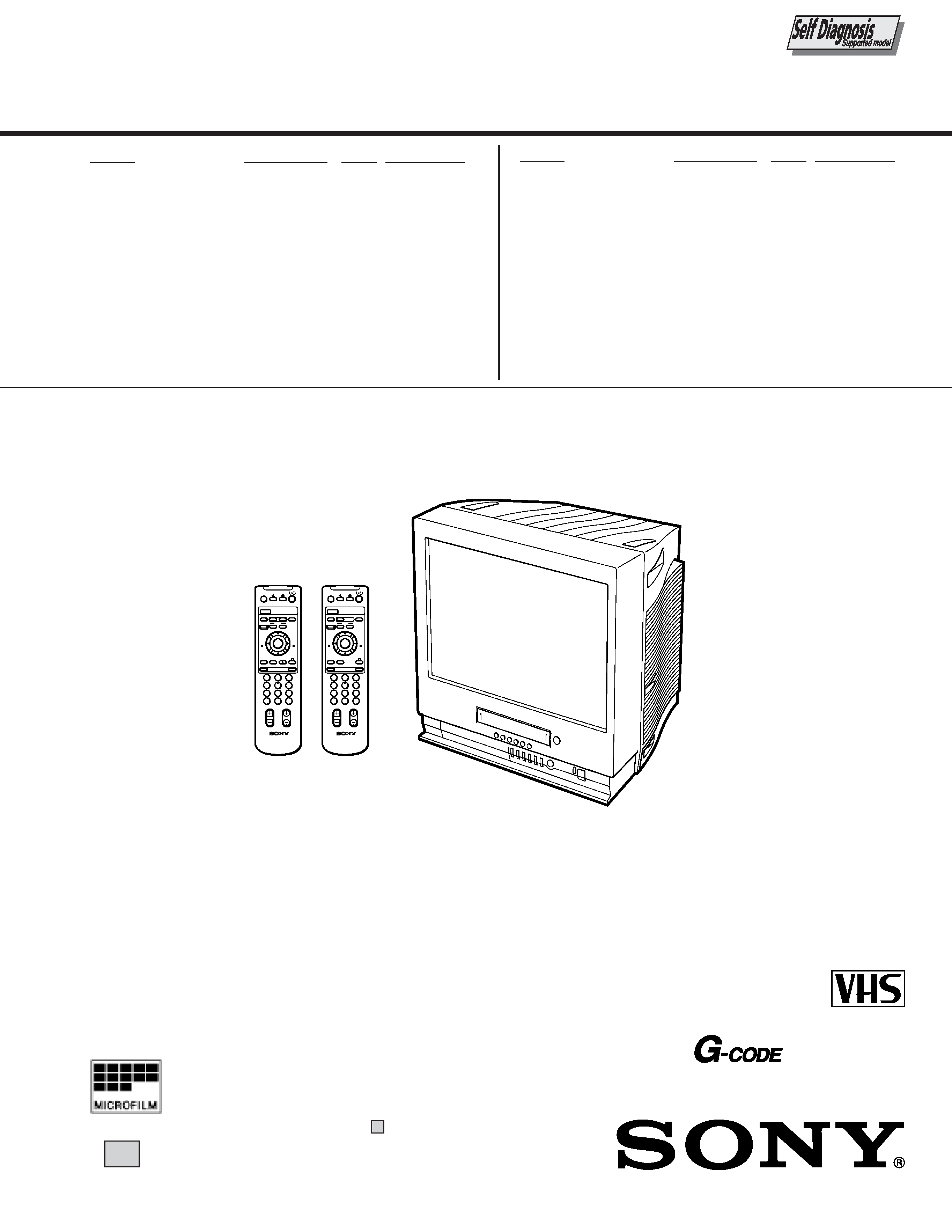
SERVICE MANUAL
CHASSIS
BC-4A
MODEL
COMMANDER
DEST. CHASSIS NO.
MODEL
COMMANDER
DEST. CHASSIS NO.
KV-VF21M40 RM-956
E
SCC-P10A-A
KV-VF21M70 RM-956
ME
SCC-P11A-A
KV-VF21M70 RM-956
JE
SCC-P12A-A
KV-VF21M70 RM-956
HK
SCC-P09B-A
KV-VF21M77 RM-955
HK
SCC-P09A-A
21
Please file according to model size. ....
TRINITRON® COLOR VIDEO TV
COUNTER RESET
t
MENU
REW
A/B
EJECT
TIMER REC
G-CODE
ON/OFF
TAPE SPEED
INDEX
zREC
GAME
2
PROGR
1
6
7
0C
9
4
3
2
5
8
X PAUSE
x STOP
m
FF
M
Z
.>
PLAY
ENTER
PIC MODE
-/--
H
COUNTER RESET
t
MENU
REW
EJECT
TIMER REC
G-CODE
ON/OFF
TAPE SPEED
INDEX
zREC
GAME
2
PROGR
1
6
7
0C
9
4
3
2
5
8
X PAUSE
x STOP
m
FF
M
Z
.>
PLAY
ENTER
PIC MODE
-/--
H
RM-955
RM-956
PAL NTSC
(VF21M77 ONLY)
®

2
SPECIFICATIONS
TV Section
Television system
B/G, I, D/K, M
Color system
PAL/SECAM and
NTSC3.58/NTSC4.43
Bilingual system
NICAM bilingual I
(VF21M77 ONLY)
Channel coverage
See "Receivable
channels and channel
display"
Picture tube
Trinitron
21 inches (approx. 50.7
cm measured
diagonally)
Antenna in
75-ohm antenna socket
for VHF/UHF
Video Section
Format
VHS standard
Video recording system
Rotary 2-head helical
scanning system
Audio recording system
Monaural
Video signal
PAL/MESECAM/
NTSC
Tape speed
PAL/MESECAM
SP: 23.39 mm/sec.
LP: 11.70 mm/sec.
NTSC
SP: 33.35 mm/sec.
EP: 11.11 mm/sec.
Maximum recording time
PAL/MESECAM
SP: 240 minutes with
E-240
LP: 480 minutes with
E-240
NTSC
SP: 180 minutes with
T-180
EP: 540 minutes with
T-180
Inputs and Outputs
Inputs
t1, t2/GAME IN
(video): phono jack
1 Vp-p, 75 ohms,
unbalanced,
sync negative
9 (audio): phono jack
Input level:
500 mVrms
Headphones jack
Minijack
General
Clock
Quartz locked
Power requirements 110-240 V AC, 50/60Hz
Power consumption 123 W
Operating temperature
5° C to 40° C
(41° F to 104° F)
Storage temperature 20° C to 60° C
(4° F to 140° F)
Dimensions
489 x 500 x 485 mm
(19 3/8 x 19 3/4 x 19 1/8
inches)
Mass
27.5 kg (60 lb 10 oz.)
Supplied accessories
Remote control
Two R6 (size AA)
batteries
Stabilizer band
Two clamps
Two wood screws
AC plug adaptor
(E/ME/JE model)
These operating
instructions
Design and specifications are subject to
change without notice.

3
Receivable channels and channel display
System
Area
Channel coverage
Channel display
B/G, H
Middle East/Asia
E-2 to E-12
C02 to C12
E-21 to E-69
C21 to C69
Indonesia
1A
C01
2 to 11
C03 to C12
Morocco
M-4 to M-7
C70 to C73
M-8 to M-10
C08 to C10
CATV
S-01 to S-05
S42 to S46
S-1 to S-41
S01 to S41
I
Hong Kong/
B-21 to B-69
C21 to C69
United Kingdom
Ireland
A, B, C,....J
C01 to C10
South Africa
4 to 13
C04 to C13
21 to 68
C21 to C68
Angola
1
C00
2 to 3
C02 to C03
CATV
S-01 to S-05
S42 to S46
S-1 to S41
S01 to S41
D/K, K1
East European
R-1 to R-12
C01 to C12
coutries
R-21 to R-60
C21 to C60
China
C-1
C01
C-2
C02
C-3
C13
C-4
C03
C-5
C04
C-6
C14
C-7 to C-12
C06 to C11
C-13 to C-24
C21 to C32
C-25 to C-47
C38 to C60
C-48 to C-57
C61 to C70
Ivory Coast
1 to 3
C71 to C73
CATV
S-1 to S-39
S01 to S39
M
America
A-2 to A-13
C02 to C13
A-14 to A-69
C14 to C69
CATV
A-8
S01
A-7
S05
A-6
S06
A-5 to A-1
S95 to S99
A to E
S14 to S18
F to W+28
S19 to S64
W+29 to W+58
S65 to S94

4
TABLE OF CONTENTS
Section
Title
Page
Section
Title
Page
SELF DIAGNOSIS FUNCTION ......................................
5
[ TV SECTION]
1. GENERAL
1-1.
KV-VF21M40/VF21M70 ........................................
8
1-2.
KV-VF21M77 ......................................................... 35
2. DISASSEMBLY
2-1.
Rear Cover Removal ............................................... 65
2-2.
Chassis Assy Removal ............................................ 65
2-3.
Service Position (A Board) ..................................... 65
2-4.
A Board Removal .................................................... 65
2-5.
Harnes Location ...................................................... 66
2-6.
Picture Tube Removal ............................................. 67
3. SET-UP ADJUSTMENTS
3-1.
Beam Landing ......................................................... 68
3-2.
Convergence ............................................................ 69
3-3.
Focus Adjustment .................................................... 70
3-4.
Screen (G2) Adjustment .......................................... 70
3-5.
White Barance Adjustment ..................................... 71
3-6.
Picture Distortion Adjustment ................................. 71
4. SAFETY RELATED ADJUSTMENT ...................... 72
CAUTION
SHORT CIRCUIT THE ANODE OF THE PICTURE TUBE AND
THE ANODE CAP TO THE METAL CHASSIS, CRT SHIELD, OR
CARBON PAINTED ON THE CRT, AFTER REMOVING THE AN-
ODE.
SAFETY-RELATED COMPONENT WARNING!!
COMPONENTS IDENTIFIED BY SHADING AND MARK
! ON
THE SCHEMATIC DIAGRAMS, EXPLODED VIEWS AND IN THE
PARTS LIST ARE CRITICAL FOR SAFE OPERATION. REPLACE
THESE COMPONENTS WITH SONY PARTS WHOSE PART
NUMBERS APPEAR AS SHOWN IN THIS MANUAL OR IN SUP-
PLEMENTS PUBLISHED BY SONY. CIRCUIT ADJUSTMENTS
THAT ARE CRITICAL FOR SAFE OPERATION ARE IDENTIFIED
IN THIS MANUAL. FOLLOW THESE PROCEDURES WHEN-
EVER CRITICAL COMPONENTS ARE REPLACED OR IM-
PROPER OPERATION IS SUSPECTED.
5. CIRCUIT ADJUSTMENTS
5-1.
Adjustments with Commander ................................ 73
5-2.
Adjustment Method ................................................. 74
5-3.
Service Data ............................................................ 75
5-4.
A Board Adjustment ................................................ 77
6. DIAGRAMS
6-1.
Block Diagrams ....................................................... 79
6-2.
Circuit Boards Location .......................................... 83
6-3.
Printed Wiring Boards and Schematic Diagrams .... 83
·
A Board .................................................................... 84
·
CV, F Boards ............................................................ 91
6. EXPLODED VIEWS
6-1.
Picture Tube ............................................................ 124
6-2.
Chassis ..................................................................... 125
7. ELECTRICAL PARTS LIST ...................................... 129
[ VIDEO SECTION]
1. GENERAL ....................................................................... 96
2. DISASSEMBLY ............................................................. 97
3. CIRCUIT ADJUSTMENTS ........................................ 98
4. INTERFACE, IC PIN FUNCTION
DESCRIPTION .............................................................. 101
5. DIAGRAMS ..................................................................... 105
6. EXPLODED VIEWS ..................................................... 126
7. ELECTRICAL PARTS LIST ...................................... 135
5
1.
OUTLINE
· The units in this manual contain a self-diagnostic function.
· If an error occurs, the STANDBY lamp will automatically begin to flash.
The number of times the lamp flashes translates to a probable source of the problem. A definition of the STANDBY lamp
flash indicators is listed in the instruction manual for the user's knowledge and reference.
· If an error symptom cannot be reproduced, the remote commander can be used to review the failure occurrence data
stored in memory to reveal past problems and how often these problems occur.
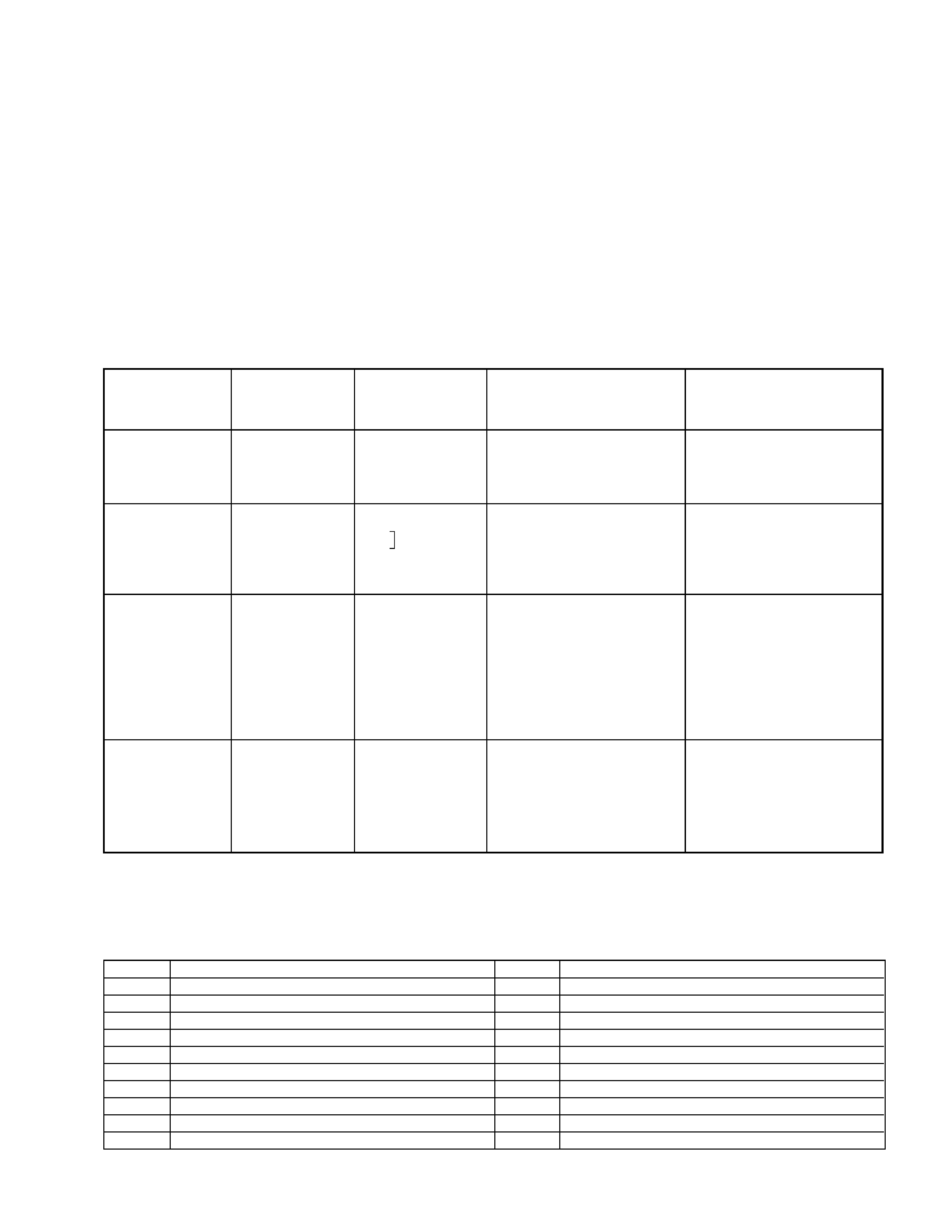
2.
DIAGNOSTIC TEST INDICATORS
· When an errors occurs, the STANDBY lamp will flash a set number of times to indicate the possible cause of the problem.
If there is more than one error, the lamp will identify the first of the problem areas.
· Result for all of the following diagnostic items are displayed on screen. No error has occured if the screen displays a "0".
Diagnostic
Item
Description
· Power does not
turn on
No. of times
STANDBY lamp
flashes
Does not light
Self-diagnostic
display/Diagnostic
result
--
Probable
Cause
Location
· Power cord is not plugged
in.
· Fuse is burned out F901
Detected
Symptoms
· Power does not come on.
· No power is supplied to the
TV.
· AC power supply is faulty.
Note 1: If a + B overcurrent is detected, stoppage of the vertical deflection is detected simultaneously.
The symptom that is diagnosed first by the microcontroller is displayed on the screen.
Note 2: Refer to screen (G2) Adjustment in section 3-4 of this manual.
SELF DIAGNOSTIC FUNCTION
· FBT
· Q802 (H OUT) shorted
2 : 0 or
2 : 1
4 : 1
2 times
4 times
5 times
· Vertical deflection
stopped
· White balance
failure (no
PICTURE)
· +B overcurrent
(OCP) or
overvoltage
(OVP)
· Has entered standby state
after horizontal raster.
· Vertical deflection pulse is
stopped.
· Horizontal deflection
stopped.
· Power line is shorted or
power supply is stopped.
4 : 0
or
4 : 1
· IC501
· IC301 !¢ pin
· IC606
· Q802 (H OUT) shorted
· Q803
· Q608
· R803 open
5 : 0
or
5 : 1
· On standby state.
· Load on power line is
shorted
(at the same time 4 : 1 on
display).
at the same
time
(Note 1)
·CRT
· IC301
· IC701 - IC703, Q701
(CV board)
· G2 is improperly adjusted.
(Note 2)
· No raster is generated.
· CRT cathode current
detection reference pulse
output is small.
Code
Coutents
00h
NO EMG
10h
CAM encode NG during unloading
11h
CAM encode NG during unloading
12h
CAM encode NG at intial
20h
T reel NG during unloading
21h
S reel FG NG
22h
T reel FG NG
23h
S reel FG NG
24h
T reel FG NG at initial
25h
S reel FG NG at initial
Code
Coutents
30h
Capstan FG NG at initial
31h
Capstan FG NG
40h
Drum FG NG
41h
Drum FG NG at initial
42h
Drum FG NG
43h
Drum PG NG
44h
Drum PG NG
50h
DEW
60h
FL NG
70h
DEW eject NG
· VCR EMG code List