MODEL
COMMANDER DEST.
CHASSIS NO.
KV-J51PF1S
RM-869E Indonesia SCC-K16J-A
KV-J51PN1
RM-869E Indonesia SCC-K16K-A
KV-J51PN21
RM-869E Indonesia SCC-K16H-A
SERVICE MANUAL
MODEL
COMMANDER DEST. CHASSIS NO.
CHASSIS
TRINITRON ® COLOR TV
BG-1S
2
KV-J51PF1S/J51PN1/J51PN21
RM-869E
SPECIFICATIONS
CAUTION
SHORT CIRCUIT THE ANODE OF THE PICTURE TUBE AND
THE ANODE CAP TO THE METAL CHASSIS, CRT SHIELD, OR
CARBON PAINTED ON THE CRT, AFTER REMOVING THE
ANODE.
SAFETY-RELATED COMPONENT WARNING!!
COMPONENTS IDENTIFIED BY SHADING AND MARK
! ON
THE SCHEMATIC DIAGRAMS, EXPLODED VIEWS AND IN THE
PARTS LIST ARE CRITICAL TO SAFE OPERATION. REPLACE
THESE COMPONENTS WITH SONY PARTS WHOSE PART
NUMBERS APPEAR AS SHOWN IN THIS MANUAL OR IN
SUPPLEMENTS PUBLISHED BY SONY.
Note
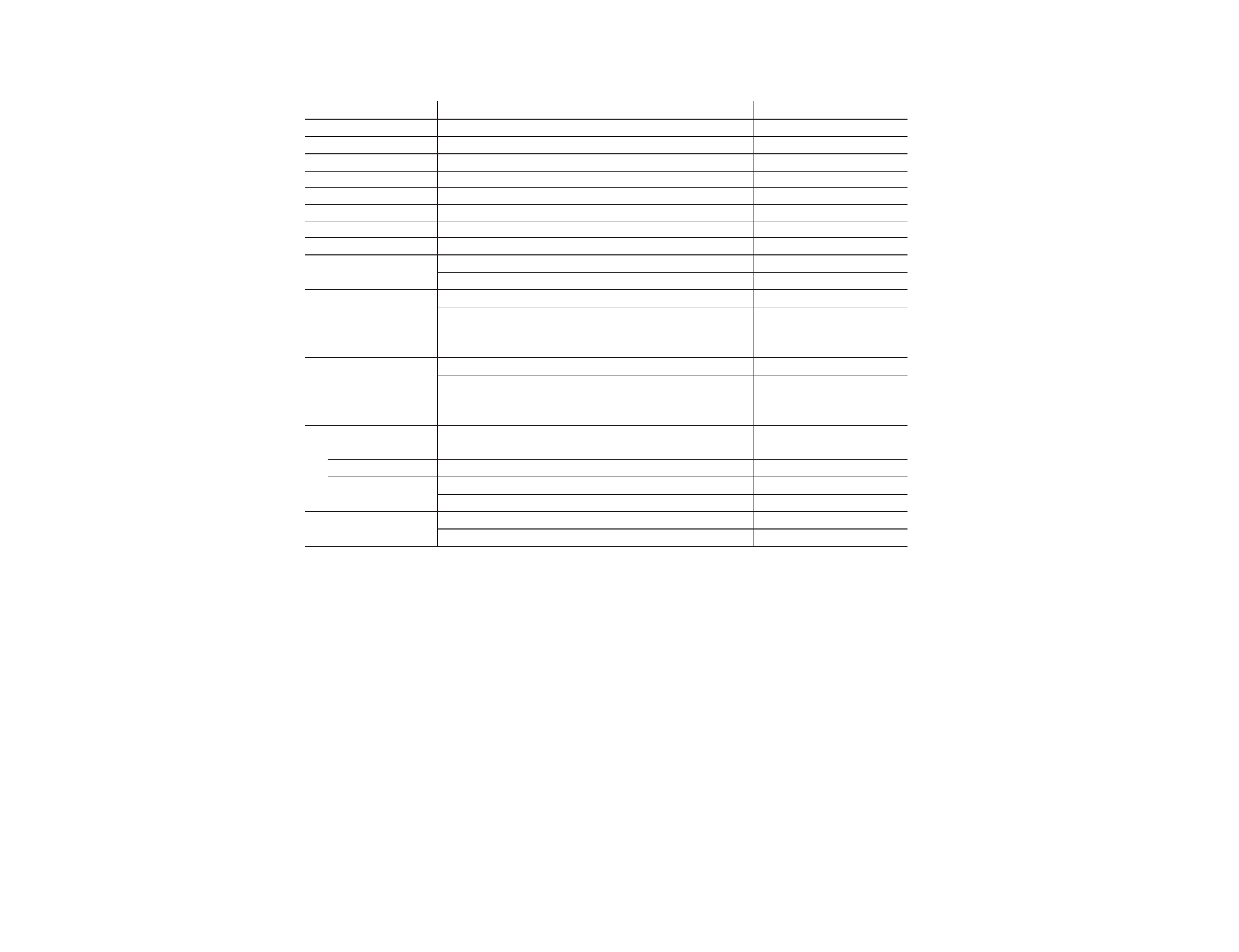
Power requirements
110-240 V AC, 50/60 Hz
Power consumption (W) Indicated on the rear of the
TV
Television system
B/G
Color system
PAL, PAL 60, NTSC4.43, NTSC3.58 (AV IN)
Stereo system
NICAM Stereo B/G, I: A2 Stereo (German) B/G
KV-J51PN1/J51PN21
Bilingual system
A2 Bilingual B/G
KV-J51PF1S
Teletext language
English, German, Swedish, Italian, French, Spanish
KV-J51PN21
Channel coverage
VHF: E2 to E12/UHF: E21 to E69/CA TV: S01 to S03, S1 to S41
Audio output (speaker)
3W + 3W
KV-J51PF1S/J51PN1
3W + 3W + 7W (3D WOOFER)
KV-J51PN21
Inputs
Antenna: 75 ohms
VIDEO IN jacks: phono jacks
Video: 1 Vp-p, 75 ohms
Audio: 500 mVrms, high impedance
Outputs
Headphone jack: minijack
MONIT OR OUT jacks: phono jacks
Video: 1 Vp-p, 75 ohms
Audio: 500 mVrms
Picture tube
21 in.
Tube size (cm)
54
Measured diagonally
Screen size (cm)
51
Measured diagonally
Dimensions (w/h/d, mm) 610
× 470 × 488
KV-J51PF1S/J51PN1
610
× 510 × 488
KV-J51PN21
Mass (kg)
23
KV-J51PF1S/J51PN1
25
KV-J51PN21
Design and specifications are subject to change without notice.

3
KV-J51PF1S/J51PN1/J51PN21
RM-869E
TABLE OF CONTENTS
1. GENERAL ....................................................................
4
2. DISASSEMBLY
2-1.
Rear Cover Removal
...........................................
11
2-2.
A Board Removal ................................................
11
2-3.
Service Position ...................................................
11
2-4.
Replacement of Parts ...........................................
12
2-5.
Demagnetization Coil Removal
..........................
12
2-6.
Picture Tube Removal .........................................
13
3. SET-UP ADJUSTMENTS
3-1.
Beam Landing ......................................................
14
3-2.
Conver gence ........................................................
15
3-3.
Focus Adjustment ................................................
17
3-4.
G2 (Screen) and White Balance Adjustments .....
17
4. SELF DIAGNOSIS FUNCTION ............................
18
5. CIRCUIT ADJUSTMENTS
5-1.
Adjustments with Commander
............................
19
5-2.
Adjustment Method .............................................
20
5-3.
A Board Adjustment after IC003 (Memory)
Replacement .........................................................
23
5-4.
Picture Distortion Adjustment .............................
23
6. DIAGRAMS
6-1.
Block Diagram ......................................................
25
6-2.
Circuit Boards Location
.......................................
29
6-3.
Schematic Diagrams and Printed
Wiring Boards
29
(1)
Schematic Diagram of A Board ............................
33
(2)
Schematic Diagrams of A3, K1 and V1 Boards ..
38
(3)
Schematic Diagrams of K and VM Boards ..........
47
(4)
Schematic Diagram of C Board ............................
51
6-4.
Semiconductors .....................................................
53
7. EXPLODED VIEW
7-1.
Chassis ..................................................................
55
7-2.
3D Speaker (KV -J51PN21) ..................................
57
8. ELECTRICAL PARTS LIST ....................................
58
Section
Title
Page
Section
Title
Page
4
KV
-J51PF1S/J51PN1/J51PN21
RM-869E
SECTION 1
GENERAL
The operating instructions mentioned here are partial abstracts from the
Operating Instructions Manual. The page numbers of the Operating
Instruction Manual remain as in this manual.
2
MONITOR
OUT
AUDIO
VIDEO
VIDEO
IN
1
2
3
3
p
KV-J51PN21
2
1
TV SYSTEM
AUTO PROGR
AUTO PROGR
5
KV
-J51PF1S/J51PN1/J51PN21
RM-869E
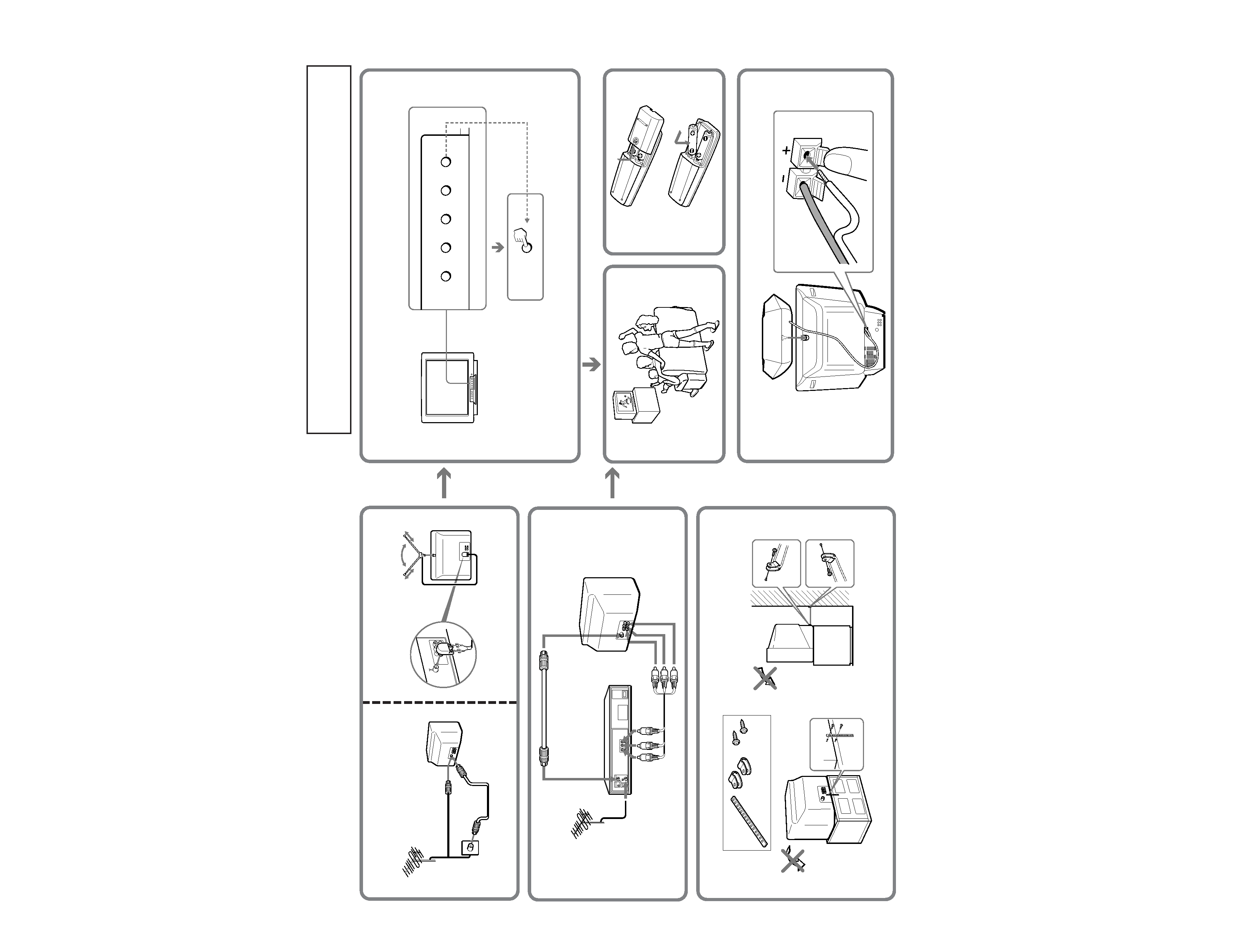
Getting Started
4
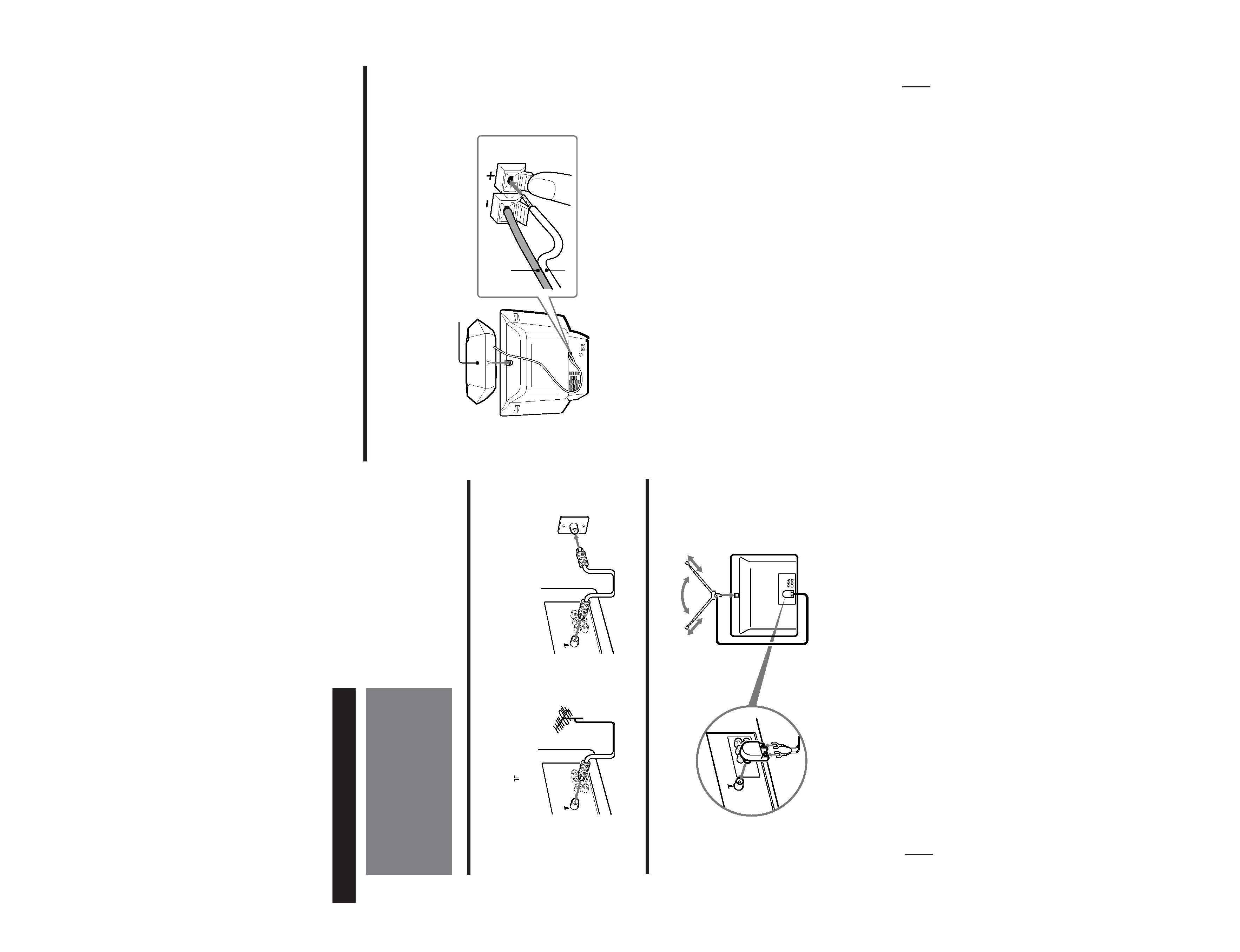
Connections
Connecting a VHF antenna or a combination VHF/UHF antenna
-- 75-ohm coaxial cable (round)
Attach an optional IEC antenna connector to the 75-ohm coaxial cable.
Plug the connector into the
(antenna) socket at the rear of the TV.
Getting Started
Connecting an indoor antenna
Note
· You are advised to use an outdoor antenna for better reception.
On a wall
or
Rear of TV
Rear of TV
2
1
MONITOR
OUT
AUDIO
VIDEO
VIDEO
IN
3
Getting Started
5
Connecting the 3D WOOFER
p
KV-J51PN21 only
1 Attach the 3D WOOFER into the foothold on the top of the TV.
2 Connect the wires to the 3D WOOFER (8) terminals at the rear of the TV.
The red wire should be connected to the ` red terminal and the black wire to the ' black terminal.
Notes
· Connect only the supplied 3D WOOFER; otherwise the TV may malfunction.
· Unplug the TV from the wall outlet when connecting the 3D WOOFER.
· To prevent a malfunction caused by a short circuit of the terminals, make sure that none of the 3D WOOFER wire strands stick out,
making contact with the neighbouring speaker terminal.
1
2
3D WOOFER
Black wire
Red wire