
HISTORY
When clicking an item, it's detail is displayed.
Date
SUP/COR No.
Description of SUP/COR
Change of
main text
1998.05
COR-1
Change of Power Cord .(P94,P121)
Yes
1998.05
COR-2
Change of Parts. L802 (P80,116)
Yes
Model Name : KV-EF29N6A/N6B/N9P
Part No.
: 9-965-209-01
SERVICE MANUAL
MODEL
COMMANDER
DEST. CHASSIS NO.
MODEL
COMMANDER
DEST. CHASSIS NO.
MICROFILM
Please file according to model size. ...
29
CHASSIS
BG-1L
TRINITRON® COLOR TV
KV-EF29N6A RM-882
AN
SCC-N80A-A
KV-EF29N6B RM-882
BRZ
SCC-N79A-A
KV-EF29N9P RM-882
MX
SCC-N78A-A

2
KV-EF29N6A/EF29N6B/EF29N9P
RM-882
CAUTION
SHORT CIRCUIT THE ANODE OF HTE PICTURE TUBE
AND THE ANODE CAP TO THE METAL CHASSIS, CRT
SHIELD, OR CARBON PAINTED ON THE CRT, AFTER
REMOVING THE ANODE.
SAFETY-RELATED COMPONENT WARNING!!
COMPONENTS IDENTIFIED BY SHADING AND MARK
¡ ON THE SCHEMATIC DIAGRAMS, EXPLODED
VIEWS AND IN THE PARTS LIST ARE CRITICAL TO
SAFE OPERATION. REPLACE THESE COMPONENTS
WITH SONY PARTS WHOSE PART NUMBERS AP-
PEAR AS SHOWN IN THIS MANUAL OR IN SUPPLE-
MENTS PUBLISHED BY SONY.
Specifications
Design and specifications are subject to change without notice.
Power requirements
Power consumption (W)
Color system
Stereo system
On-screen language
Channel coverage
(Antenna)
Audio output (speaker)
Number of terminal
VIDEO
AUDIO
S1 VIDEO
COMPONENT VIDEO
2
(Headphones)
Picture tube
Tube size (cm)
Screen size (cm)
Dimensions (w/h/d, mm)
Mass (kg)
KV-EF29N6B
KV-EF29N6A, KV-EF29N9P
Note
110-240 V AC, 50/60 Hz
183
NTSC, PAL M
NTSC, PAL N
MTS
English/Spanish
VHF : 2-13/UHF : 14-69/CATV : 1-125
75-ohm external terminal
15W + 15W
Input: 4 Output: 1
phono jacks; 1 Vp-p, 75 ohms
Input: 4 Output: 1
phono jacks; 500 mVrms
Input: 2
Y: 1 Vp-p, 75 ohms,
unbalanced, sync negative
C: 0.286 Vp-p, 75 ohms
Input: 1
phono jacks
Y: 1.0 Vp-p, 75 ohms,
sync negative
CB : 0.7 Vp-p, 75 ohms
CR : 0.7 Vp-p, 75 ohms
Audio: 500 mVrms
Output: 1
Minijack
29 in.
72
68
716
× 572 × 525
54
Measured
diagonally
Measured
diagonally

3
KV-EF29N6A/EF29N6B/EF29N9P
RM-882
1. GENERAL .................................................................
4
2. DISASSEMBLY
2-1.
Rear Cover Removal .........................................
20
2-2.
Speaker Box Assy Removal ..............................
20
2-3.
Chassis Assy Removal ......................................
20
2-4.
Service Position .................................................
20
2-5.
Terminal Bracket, Printed Wiring Board Holder,
DH Bracket Removal ........................................
21
2-6.
Picture Tube Removal ........................................
22
2-7.
Wiring Harness Layout ......................................
23
3. SET-UP ADJUSTMENTS ...................................
24
3-1.
Beam Landing ...................................................
24
3-2.
Convergence ......................................................
25
3-3.
Focus Adjustment ..............................................
28
3-4.
G2 (Screen) and White Balance Adjustments ...
29
4. SELF DIAGNOSIS FUNCTION .....................
30
5. CIRCUIT ADJUSTMENTS ................................
31
5-1.
Adjustments with Commander .........................
31
5-2.
Adjustment Method ...........................................
32
5-3.
Picture Quality Adjustments .............................
37
5-4.
Display Position Adjustments ...........................
37
5-5.
A Board Adjustment After IC003
(MEMORY) Replacement ................................
38
TABLE OF CONTENTS
6. DIAGRAMS
6-1.
Block Diagrams ..................................................
39
6-2.
Circuit Boards Location .....................................
52
6-3.
Schematic Diagrams and Printed Wiring
Boards .................................................................
53
(1)
Schematic Diagram of A Board ........................
57
(2)
Schematic Diagrams of H7, J, P3 and
P4 Boards ...........................................................
62
(3)
Schematic Diagrams of B3, C1 and
VM Boards ........................................................
73
(4)
Schematic Diagrams of D, D2 and
DH Boards .........................................................
78
(5)
Schematic Diagrams of A4, A5 and
S1 Boards ...........................................................
86
6-4.
Semiconductors .................................................
91
7. EXPLODED VIEWS
7-1.
Speaker Box ......................................................
93
7-2.
Chassis ...............................................................
94
7-3.
Picture Tube ......................................................
95
8. ELECTRICAL PARTS LIST ............................
97
Section
Title
Page
Section
Title
Page
4
SECTION 1
GENERAL
The operating instructions mentioned here are partial abstracts
from the Operating Instruction Manual. The page numbers of
the Operating Instruction Manual remain as in the manual.
4
Using Your New TV
VIDEO
VIDEO IN
VIDEO OUT
AUDIO
VIDEO IN
MON/TV
OUT
VIDEO
L(MONO)
AUDIO
R
S1 VIDEO
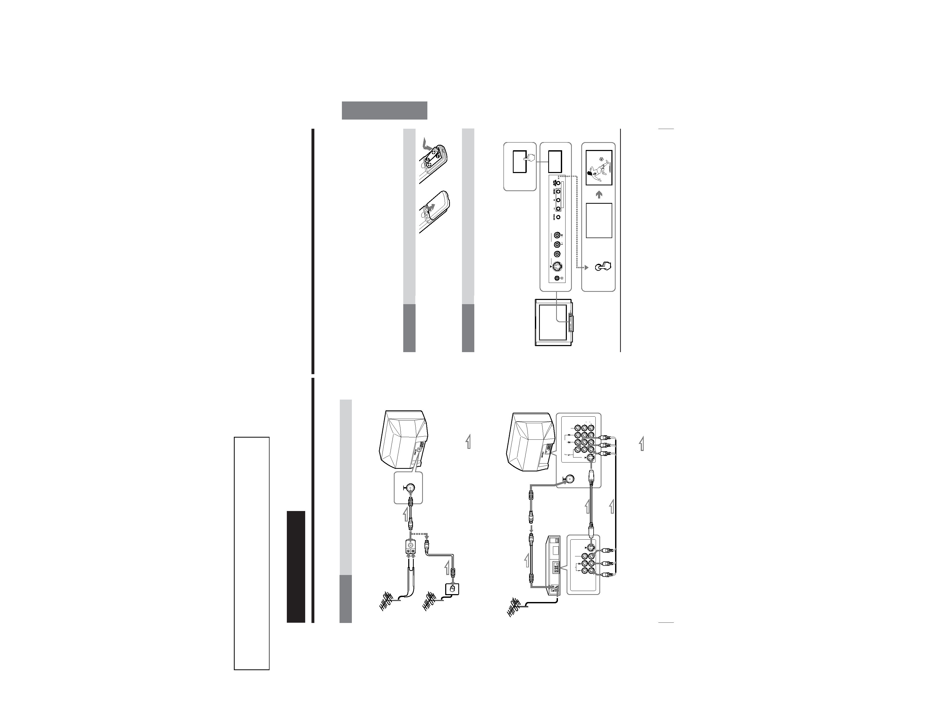
Getting Started
Step 1
Connect the antenna
If you wish to connect a VCR, see the "Connecting a VCR" diagram below.
Connecting a VCR
Using Your New TV
To video and
audio outputs
VCR
VIDEO (yellow)
AUDIO-L (MONO)(white)
AUDIO-R (red)
To S video
output
Antenna cable
(not supplied)
To VIDEO IN 1,
2, or 3
Audio/Video cable
(not supplied)
S video cable
(not supplied)
: Signal flow
To S1 VIDEO
To antenna
output
To
(antenna)
or
: Signal flow
Antenna
cable
(supplied)
Antenna cable
(not supplied)
Antenna
connector
(not supplied)
Antenna cable
(supplied)
5
Using Your New TV
Using
Y
our
New
TV
Notes
· If you connect a monaural VCR, connect the yellow plug to VIDEO (the
yellow jack) and the black plug to AUDIO-L (MONO) (the white jack).
· If you connect a VCR to the (antenna) terminal, preset the signal
output from the VCR to the program position 0 on the TV.
· Do not simultaneously connect video equipment to the VIDEO 3 INPUT
jacks at the front and the VIDEO IN 3 jacks at the rear of your TV.
· If both S1 VIDEO and VIDEO of VIDEO IN 1 are input simultaneously, the
S1 VIDEO is automatically selected. To view the video input to VIDEO IN
1, disconnect the S video cable.
· When no signal is input to the connected VCR (or video equipment), the
screen becomes blue.
Step 2
Insert the batteries
into the remote
Note
· Do not use old batteries nor use different types of batteries together.
Step 3
Preset the channels
Notes
· When you use the TV for the first time, preset the channels by
pressing AUTO PROGR button inside the front cover.
· If you use a cable TV system, select "CABLE : ON" of the
PRESET menu before presetting the channels. (See "Changing
other PRESET menu options" on page 30.)
Now You Are Ready. . .
The channels are now automatically preset in your TV. To preset the channels
manually, see "Adding or erasing channels" on page 28.
1
2 AUTO
PROGR
1
MAIN POWER
ONE-PUSH AUTOMATIC PROGRAMING
MAIN POWER
VIDEO 3 INPUT
(MONO)
AUDIO
VIDEO
S1 VIDEO
AUTO PROGRAM
1