MODEL
COMMANDER DEST. CHASSIS NO.
KV-E29MF8
RM-871
E
SCC-K60H-A
KV-E29MF8
RM-871
ME
SCC-K57M-A
KV-E29MF8S RM-871
GE
SCC-K52J-A
KV-E29MH8
RM-871
HK
SCC-K56F-A
MODEL
COMMANDER DEST. CHASSIS NO.
CHASSIS
TRINITRON® COLOR TV
SERVICE MANUAL
BG-1L
KV-E29MH81 RM-871
E
SCC-K60G-A
KV-E29MH81 RM-871
ME
SCC-K57L-A
KV-E29MN81 RM-871
GE
SCC-K52H-A
KV-E29SN81
RM-871
OCE
SCC-U08B-A

2
SPECIFICATIONS
KV-E29MF8, KV-E29MF8S, KV-E29MH8, KV-E29MH81,
KV-E29MN81, KV-E29SN81
Note
Power requirements
110-240 V AC, 50/60 Hz
Power consumption (W) Indicated on the rear of TV
Television system
B/G, I, D/K, M
Color system
PAL, PAL 60, SECAM, NTSC4.43, NTSC3.58
Stereo system
NICAM Stereo B/G, I; A2 Stereo (German) B/G
KV-E29MH8/E29MH81
KV-E29MN81
Teletext language
English, German, Swedish, Italian, French, Spanish
KV-E29MH81/E29MN81
Channel coverage
B/G
VHF: E2 to E12 / UHF: E21 to E69 / CATV: S01 to S03, S1 to S41
I
UHF: B21 to B68 / CATV: S01 to S03, S1 to S41
D/K
VHF: C1 to C12, R1 to R12 / UHF: C13 to C57, R21 to R60
CATV: Z1 to Z39, S01 to S03, S1 to S41
M
VHF: A2 to A13 / UHF: A14 to A79 /
CATV: A-8 to A-2, A to W+4, W+6 to W+84
Antenna
75-ohm external antenna terminal
Audio output (speaker)
15W
× 15W
Number of terminal
Video
Input: 4 Output:1
Phono jacks; 1 VP-P, 75 ohms
Audio
Input: 4 Output: 1
Phono jacks; 500 mVrms
S Video
Input: 2
Y : 1 Vp-p, 75 ohms,
unbalanced, sync
negative
C : 0.286 Vp-p, 75 ohms
Headphone
Output : 1
Minijack
Picture tube
29 inch (Super Trinitron Plus)
Tube size (cm)
72
Measured diagonally
Screen size (cm)
68
Measured diagonally
Dimension (w/h/d, mm)
706
× 577 × 525
Mass (kg)
48.5
Accessories (optional)
TV stand (SU-E29G)
CAUTION
SHORT CIRCUIT THE ANODE OF THE PICTURE TUBE
AND THE ANODE CAP TO THE METAL CHASSIS, CRT
SHIELD, OR CARBON PAINTED ON THE CRT, AFTER
REMOVING THE ANODE.
SAFETY-RELATED COMPONENT WARNING!!
COMPONENTS IDENTIFIED BY SHADING AND MARK
!
ON THE SCHEMATIC DIAGRAMS, EXPLODED VIEWS AND
IN THE PARTS LIST ARE CRITICAL TO SAFE OPERATION.
REPLACE THESE COMPONENTS WITH SONY PARTS
WHOSE PART NUMBERS APPEAR AS SHOWN IN THIS
MANUAL OR IN SUPPLEMENTSÅ PUBLISHED BY SONY.
Design and specifications are subject to change without notice.

3
TABLE OF CONTENTS
1. GENERAL ........................................................................ 4
2. DISASSEMBLY
2-1.
Rear Cover Removal ................................................ 16
2-2.
Speaker Removal ..................................................... 16
2-3.
Chassis Assy Removal ............................................. 16
2-4.
Service Position ....................................................... 17
2-5.
P1 and V1 Boards Removal .................................... 17
2-6.
P2 and S1 Boards Removal ..................................... 17
2-7.
B1 Board Removal .................................................. 18
2-8.
A and D Boards Removal ........................................ 18
2-9.
F1 and H2 Boards Removal .................................... 18
2-10. DGC Removal .......................................................... 18
2-11. H4 Board Removal .................................................. 19
2-12. Picture Tube Removal .............................................. 19
3. SET-UP ADJUSTMENTS
3-1.
Beam Landing .......................................................... 21
3-2.
Convergence ............................................................. 22
3-3.
Focus Adjustment .................................................... 25
3-4.
G2 (Screen) and White Balance Adjustments ......... 26
4. SELF DIAGNOSIS FUNCTION ................................ 27
5. CIRCUIT ADJUSTMENTS
5-1.
Adjustments with Commander ................................ 28
5-2.
Adjustment Method ................................................. 29
5-3.
Picture Quality Adjustments .................................... 33
5-4.
A Board Adjustment ................................................ 33
5-5.
A Board Adjustment After IC003 (Memory)
Replacement ............................................................. 34
5-6.
Picture Distortion Adjustment ................................. 34
6. DIAGRAMS
6-1.
Block Diagram ......................................................... 35
6-2.
Frame Schematic Diagram ...................................... 37
6-3
Circuit Boards Location .......................................... 40
6-4.
Schematic Diagrams and Printed Wiring Boards .... 40
(1)
Schematic Diagrams of D, F1, H2
and H4 Boards ......................................................... 45
(2)
Schematic Diagrams of A Board ............................. 49
(3)
Schematic Diagrams of B1, P1, P2
and VM Boards ........................................................ 59
(4)
Schematic Diagrams of A3, C1, and S1 Boards ..... 63
(5)
Schematic Diagrams of V1 Board ........................... 68
6-5.
Semiconductors ........................................................ 70
7. EXPLODED VIEWS
7-1.
Picture Tube ............................................................. 72
7-2.
Chassis ..................................................................... 73
8. ELECTRICAL PARTS LIST ....................................... 74
Section
Title
Page
Section
Title
Page
4
SECTION 1
GENERAL
The operating instructions mentioned here are partial abstracts from the
Operating Instr uctions Manual. The page numbers of the Operating
Instruction Manual remain as in this manual.
Getting Started
6-EN
VIDEO IN
MON/TV
OUT
12
3
VIDEO
AUDIO
L (MONO)
R
S VIDEO
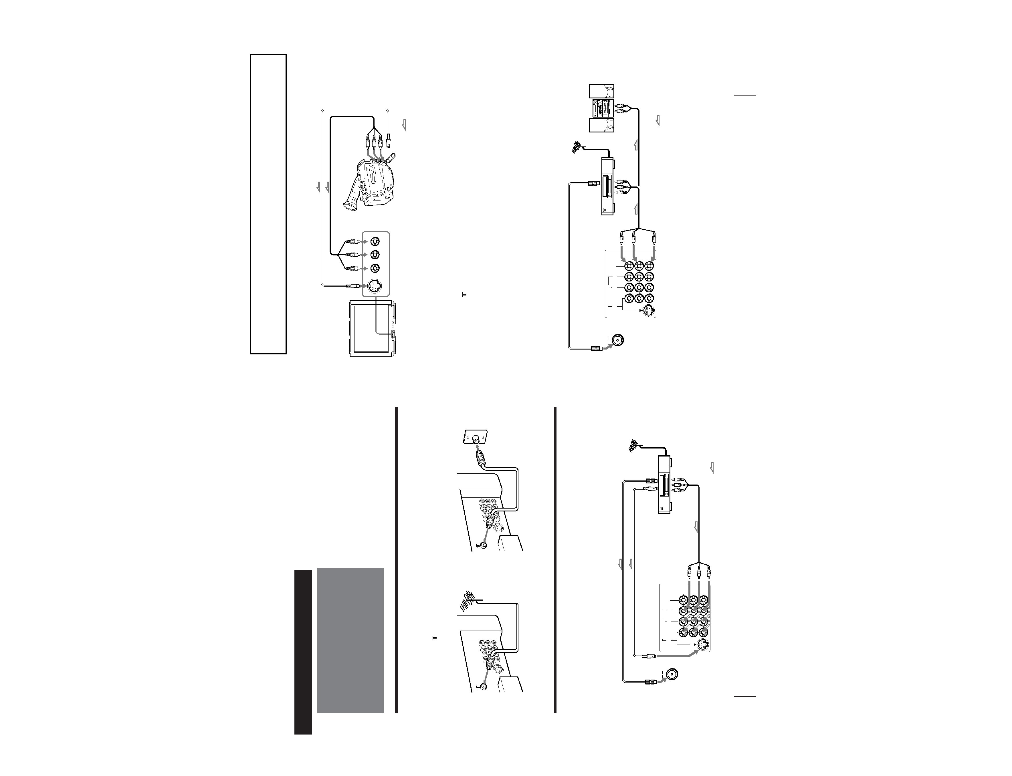
Connecting a VHF antenna or a combination VHF/UHF antenna
-- 75-ohm coaxial cable (round)
Attach an optional IEC antenna connector to the 75-ohm coaxial cable.
Plug the connector into the
(antenna) socket at the rear of the TV.
Connecting optional equipment
You can connect optional audio/video equipment to your TV such as a VCR, multi disc player, camcorder, video
game or stereo system.
Connecting video equipment using video input jacks
Connections
On a wall
Rear of TV
Rear of TV
or
Rear of TV
VIDEO (yellow)
AUDIO-L (white)
AUDIO-R (red)
VCR
to
S Video
output
to
antenna
output
to video and
audio outputs
: Signal flow
Getting Started
to
antenna
socket
to
S Video
input
Getting Started
-EN
7
VIDEO IN
MON/TV
OUT
12
3
VIDEO
AUDIO
L (MONO)
R
S VIDEO
When connecting a monaural VCR
Connect the yellow plug to VIDEO and the black plug to AUDIO-L (MONO).
When connecting video game equipment
Connect video game equipment to the VIDEO 3 INPUT jacks at the front of your TV or the VIDEO IN 3 jacks at the rear of your TV.
When connecting a VCR to the
(antenna) terminal
Preset the signal output from the VCR to the program position 0.
When connecting video equipment to the VIDEO 3 INPUT jacks or the VIDEO IN 3 jacks
Do not connect video equipment to the VIDEO 3 INPUT jacks at the front and the VIDEO IN 3 jacks at the rear of your TV simultaneously;
otherwise the picture will not be displayed properly on the screen.
If both S Video and video signals are input simultaneously
The S Video input signal is selected. To view a video input signal, disconnect the S Video connection.
Note on the video input
When no signal is input, the screen becomes blue.
Connecting audio/video equipment using MON/TV OUT jacks
VIDEO
VIDEO 3 INPUT
S VIDEO
(MONO)
LAUDIOR
Front of TV
Camcorder
to S video output
to video and
audio outputs
: Signal flow
Rear of TV
VCR
to
antenna
output
to video and
audio inputs
VIDEO (yellow)
AUDIO-L (white)
AUDIO-R (red)
Audio system
to audio
inputs
: Signal flow
to
antenna
socket
or
5
Getting Started
8-EN
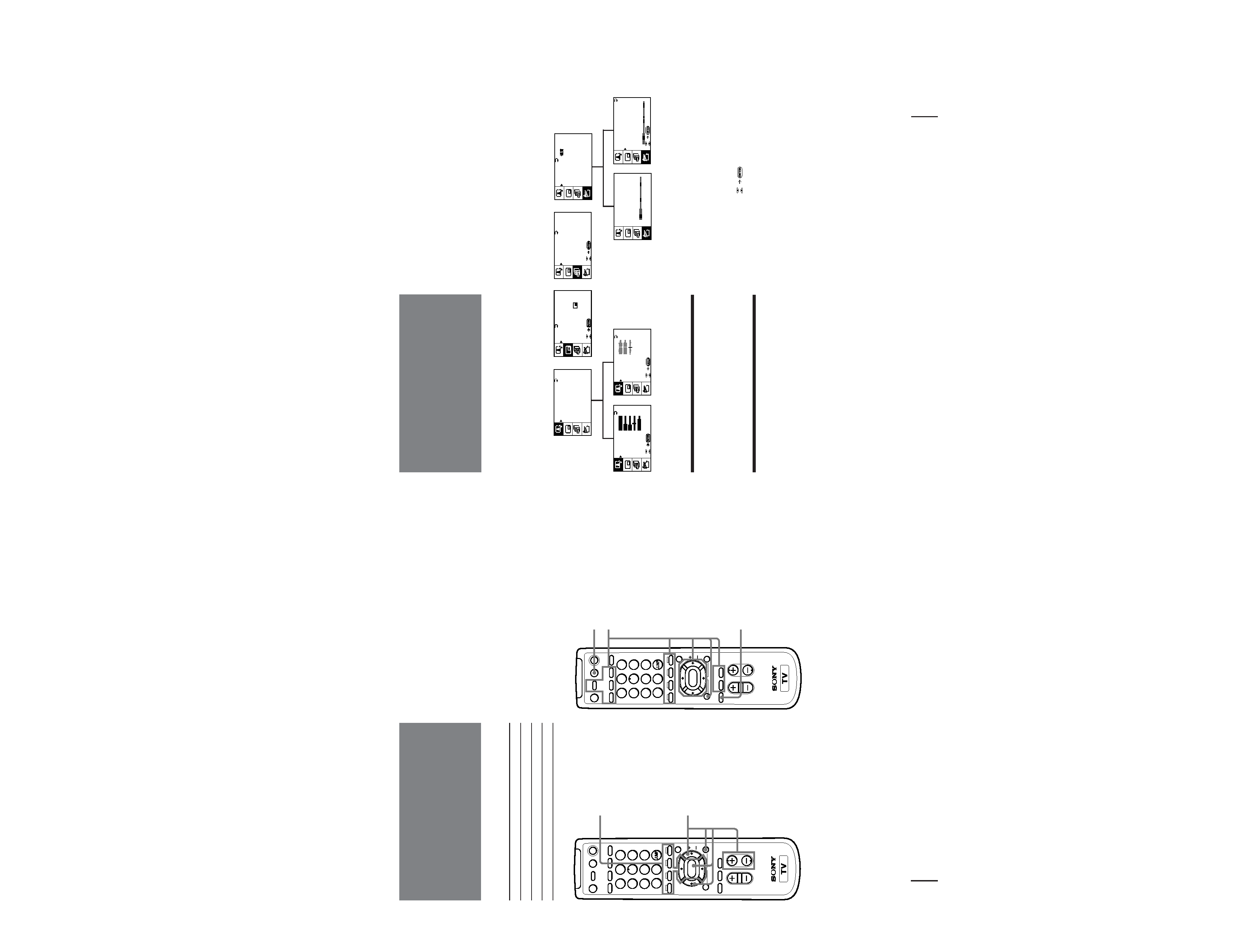
Names of buttons on the remote commander are indicated in different colors to represent the available functions.
Label color
Button function
White
For general TV operations.
Green
For Teletext operations.
Yellow
For PIP and PROGRAM INDEX operations.
Notes
· The Teletext operation buttons are used for KV-E29MH81 and KV-E29MN81 only.
· The A/B button is used for KV-E29MH8, KV-E29MH81 and KV-E29MN81 only.
PROGR
VOL
MENU
PIP PROGR
TEXT
A/B
ENLARGE
DISPLAY
REVEAL
GAME
POWER
VIDEO
HOLD
TV
MUTING
PROGR
INDEX
PIP
TEXT
1
2
3
4
5
6
7
8
0
-/--
9
TV/VIDEO
FREEZE
SWAP
PIP
POWER
BASSO
WAKE UP
INDEX
SLEEP
TEXT CLR
ENTER
Getting to know the
remote commander
PIP operation buttons
TV/VIDEO (page 22)
FREEZE (page 23)
SWAP (page 23)
PIP (page 22)
V/v/ENTER
for PIP PROGR (page 22)
PROGRAM INDEX
operation buttons
PROGR INDEX (page 21)
V/b/v/B/ENTER (page 21)
PROGR +/ (page 21)
GAME (page 27)
Teletext operation buttons
TEXT (page 24, 25)
ENLARGE (page 25)
REVEAL (page 25)
HOLD (page 24)
[ ]
Red (page 24)
[ ]
Green (page 24)
[ ]
Yellow (page 24)
[ ]
Blue (page 24)
INDEX (page 24)
TEXT CLR (page 25)
PIP TEXT (page 26)
V/b/v/B/ ENTER (page 26)
POWER BASSO (page 18)
PROGR
VOL
MENU
PIP PROGR
TEXT
A/B
ENLARGE
DISPLAY
REVEAL
GAME
POWER
VIDEO
HOLD
TV
MUTING
PROGR
INDEX
PIP
TEXT
1
2
3
4
5
6
7
8
0
-/--
9
TV/VIDEO
FREEZE
SWAP
PIP
POWER
BASSO
WAKE UP
INDEX
SLEEP
TEXT CLR
ENTER
Getting Started
-EN
9
A/V CONTROL
PIP
FEATURES
Getting back to the previous menu
(except for AUTO PROGRAM)
Press V or v to move the cursor (z) to the first
line (N) of each menu, and press ENTER.
Cancelling the menu screen
Press MENU.
Notes (except for AUTO PROGRAM)
· When a menu is selected after pressing ENTER, the color of
both the menu and the menu symbol change and the cursor
(z) appears beside the first item of the menu.
· When an item on the menu is selected after pressing ENTER,
the color of the item changes.
· You can refer to the guide (
) at the bottom of the
menus (except for the A/V CONTROL and PRESET menus)
for the basic operations of the menu.
· If more than approximately 60 seconds elapse after you press a
button, the menu screen disappears automatically.
PI P
P IP:
OF F
P IP TE X T
STROB E
POS I T I ON:
PROGR
I ND EX
PRESET
BASS
80
00
80
TREBLE
BALANCE
A UD I O AD J UST
Introducing the
menus
You can preset TV channels, adjust the picture and sound qualities, and select some settings using the on-screen
menus. You can use the buttons on both the remote commander and the TV to operate the menus.
A / V CONT ROL
DY NAMIC
SOF T
S T A NDARD
P ERSONAL
V I DEO AD J UST
A UD I O AD J UST
T I L T CORRECT:
0
PRES E T
S KIP:
PR0 2 OFF
TV S Y S :
B / G
COL SYS : AUTO
ENGL I SH
AUTO PROGRAM
MANUA L PROGRAM
L A NGUAGE /
:
P I C T URE
40
100
0
80
V I DEO AD J UST
COL OR
BR I GHT
HUE
SHARP
VM :
HIGH
45
0
TV S Y S :
B / G
AUTO PROGRAM
VHF L O W
PR : 0 1
TV S Y S :
B / G
VHF LO W
PR : 0 1
AT T :
OFF
MANUA L PROGRAM
GAME MODE
HYPER S URROUND :
OF F
MONITOR
AV OUT :
F E AT URES
(
KV-E29MH81/E29MN81 only)