-- 1 --
KV-32XBR200/KV-36XBR200
TRINITRON® COLOR TV
SERVICE MANUAL
CHASSIS
AA-2H
MODEL
COMMANDER
DEST.
CHASSIS NO.
KV-32XBR200
RM-Y144
US
SCC-S18A-A
KV-32XBR200
RM-Y144
CND
SCC-S19A-A
KV-36XBR200
RM-Y144
US
SCC-S18D-A
KV-36XBR200
RM-Y144
CND
SCC-S19D-A
RM-Y144
KV-36XBR200
-- 2 --
KV-32XBR200/KV-36XBR200
SPECIFICATIONS
Television system
American TV standard, NTSC
Channel coverage
VHF:2-13 / UHF:14-69 / CATV:1-125
Visible screen size
32-inch picture measured diagonally (KV-32XBR200)
36-inch picture measured diagonally (KV-36XBR200)
Actual screen size
34-inch picture measured diagonally (KV-32XBR200)
38-inch picture measured diagonally (KV-36XBR200)
Antenna
75 ohm external antenna terminal for VHF/UHF
Picture tube
FD Trinitron® tube
Supplied accessories
Remote control RM-Y144
Battery size AA (R6) 2
Optional accessory
Connecting Cables
RK-74A, RK-G69HG,
VMC-10HG, VMC-720M,
VMC-810S/820S, YC-15V/30V,
TV Stand SU-32FD1, SU-36FD1
U/V mixer EAC-66
Design and specifications are subject to change without notice.
1) 1 Vp-p 75 ohms unbalanced, sync negative
2) Y: 1 Vp-p 75 ohms unbalanced, sync negative
C: 0.286 Vp-p (Burst signal), 75 ohms
3) 500 mVrms (100% modulation), Impedance: 47 kilohms
4) More than 408 mVrms at the maximum volume setting (variable)
More than 408 mVrms (fix); Impedance (Output): 2 kilohms
5) Y: 1.0 Vp-p, 75 ohms, sync negative; PB: 0.7 Vp-p, 75 ohms; PR: Vp-p, 75 ohms
KV-32XBR200
KV-36XBR200
Power requirements
120V, 60Hz
Number of inputs/outputs:
Video 1)
3
S Video 2)
2
Audio 3)
4
Audio Out 4)
1
Monitor Out
1
TV Out 1) 3)
1
S-link
3
Y, PB, PR 5)
1
Speaker output (W)
15W x 2
Power Consumption (W):
In use (max.)
240W
In standby
2W
Dimensions (W/H/D):
(mm)
889.4 x 685.6 x 600.7 mm
1010 x 761.2 x 630.9 mm
(in.)
357/16 x 27 x 2321/32 in
3513/16 x 30 x 2415/16 in
Mass:
(kg.)
79 kg
107 kg
(lbs.)
175 lbs
236 lbs
(
) ® SRS (SOUND RETRIEVAL SYSTEM)
The (
) SRS (SOUND RETRIEVAL SYSTEM) is manu-
factured by Sony Corporation under license from SRS Labs,
Inc. It is covered by U.S. Patent No. 4,748,669. Other U.S.
and foreign patents pending.
The word `SRS' and the SRS symbol (
) are registered
trademarks of SRS Labs, Inc.
BBE and BBE symbol are trademarks of BBE Sound, Inc.
and are licensed by BBE Sound, Inc. under U.S. Patent
No. 4,638,258 and 4,482,866.
-- 3 --
KV-32XBR200/KV-36XBR200
1. GENERAL
Remote Control ............................................................. 5
Connecting and Installing the TV .................................. 5
Cable Box Connections ............................................ 5
VCR Connections ...................................................... 5
DBS Connections ...................................................... 6
DVD Player Connections .......................................... 6
Additional Connections ............................................. 6
Using your New TV ....................................................... 7
Watching the TV ........................................................ 8
Watching two programs at one time - PIP ................. 8
Using Your Menus ........................................................ 9
Learning menu selection ........................................... 9
Using the VIDEO menu ............................................. 9
Using the AUDIO menu ........................................... 10
Using the TIMER menu ........................................... 10
Using the SET UP menu ......................................... 10
Operating Video Equipment ....................................... 12
VCR manufacturer code numbers ........................... 12
MDP manufacturer code numbers .......................... 12
Operating a cable box DBS or DBS receiver .............. 12
Troubleshooting .......................................................... 12
2. DISASSEMBLY
2-1.
Rear Cover and Speaker Removal ..................... 13
2-2.
Chassis Assembly Removal ............................. 13
2-3.
Service Position ................................................ 13
2-4.
Control Assy Removal ...................................... 13
2-5.
Extension Cable Removal ................................ 14
2-6.
Picture Tube Removal ...................................... 15
TABLE OF CONTENTS
Section
Title
Page
Section
Title
Page
3. SET-UP ADJUSTMENTS
3-1.
Beam Landing ................................................... 16
3-2.
Convergence .................................................... 17
3-3.
Focus ................................................................ 18
3-4.
Screen (G2) ...................................................... 18
3-5.
White Balance Adjustment ................................ 18
4. SAFETY RELATED ADJUSTMENTS ........................ 19
5. CIRCUIT ADJUSTMENTS ......................................... 20
6. DIAGRAMS
6-1.
Block Diagram .................................................. 31
6-2.
Circuit Boards Location ..................................... 34
6-3.
Printed Wiring Boards and Schematic Diagrams . 39
· A Board ........................................................... 39
· AX Board ........................................................ 45
· BX Board ........................................................ 47
· HF Board ........................................................ 50
· HX Board ........................................................ 50
· C Board .......................................................... 51
· G Board .......................................................... 53
· K Board ........................................................... 55
· WA Board ....................................................... 57
· PX Board ........................................................ 59
· UX Board ........................................................ 63
6-4.
Semiconductors ................................................ 68
7. EXPLODED VlEWS
7-1.
Chassis ............................................................. 69
7-2.
Picture Tube ..................................................... 70
8. ELECTRICAL PARTS LIST ....................................... 71
ATTENTION!!
AFIN D'EVITER TOUT RESQUE D'ELECTROCUTION PROVENANT D'UN
CHÁSSIS SOUS TENSION, UN TRANSFORMATEUR D'ISOLEMENT DOIT
ETRE UTILISÉ LORS DE TOUT DÉPANNAGE. LE CHÁSSIS DE CE
RÉCEPTEUR EST DIRECTEMENT RACCORDÉ À L'ALIMENTATION
SECTEUR.
ATTENTION AUX COMPOSANTS RELATIFS A LA SECURITE!!
LES COMPOSANTS IDENTIFIES PAR UNE TRAME ET PAR UNE MARQUE
¡ SUR LES SCHEMAS DE PRINCIPE, LES VUES EXPLOSEES ET LES
LISTES DE PIECES SONT D'UNEIMPORTANCE CRITIQUE POUR LA
SECURITE DU FONCTIONNEMENT. NE LES REMPLACER QUE PAR DES
COMPOSANTS SONY DONT LE NUMERO DE PIECE EST INDIQUE DANS
LE PRESENT MANUEL OU DANS DES SUPPLEMENTS PUBLIES PAR
SONY. LES REGLAGES DE CIRCUIT DONT L'IMPORTANCE EST CRI-
TIQUE POUR LA SECURITE DU FONCTIONNEMENT SONT IDENTIFIES
DANS LE PRESENT MANUEL. SUIVRE CES PROCEDURES LORS DE
CHAQUE REMPLACEMENT DE COMPOSANTS CRITIQUES, OU
LORSQU'UN MAUVAIS FONTIONNEMENT SUSPECTE.
ATTENTION
APRES AVOIR DECONNECTE LE CAP DE L'ANODE, COURT-CIRCUITER
L'ANODE DU TUBE CATHODIQUE ET CELUI DE L'ANODE DU CAP AU
CHASSIS METALLIQUE DE L'APPAREIL, OU AU COUCHE DE CARBONE
PEINTE SUR LE TUBE CATHODIQUE OU AU BLINDAGE DU TUBE
CATHODIQUE.
CAUTION!
SHORT CIRCUIT THE ANODE OF THE PICTURE TUBE AND THE
ANODE CAP TO THE METAL CHASSIS, CRT SHIELD, OR CARBON
PAINTED ON THE CRT, AFTER REMOVING THE ANODE.
WARNING!!
AN ISOLATION TRANSFORMER SHOULD BE USED DURING ANY
SERVICE TO AVOID POSSIBLE SHOCK HAZARD, BECAUSE OF LIVE
CHASSIS.
THE CHASSIS OF THIS RECEIVER IS DIRECTLY CONNECTED TO
THE AC POWER LINE.
SAFETY-RELATED COMPONENT WARNING!!
COMPONENTS IDENTIFIED BY SHADING AND MARK
¡ ON
THE SCHEMATIC DIAGRAMS, EXPLODED VIEWS AND IN THE
PARTS LIST ARE CRITICAL FOR SAFE OPERATION. REPLACE
THESE COMPONENTS WITH SONY PARTS WHOSE PART
NUMBERS APPEAR AS SHOWN IN THIS MANUAL OR IN
SUPPLEMENTS PUBLISHED BY SONY. CIRCUIT ADJUSTMENTS
THAT ARE CRITICAL FOR SAFE OPERATION ARE IDENTIFIED
IN THIS MANUAL. FOLLOW THESE PROCEDURES WHENEVER
CRITICAL COMPONENTS ARE REPLACED OR IMPROPER
OPERATION IS SUSPECTED.
-- 4 --
KV-32XBR200/KV-36XBR200
SAFETY CHECK-OUT
After correcting the original service problem, perform the
following safety checks before releasing the set to the
customer:
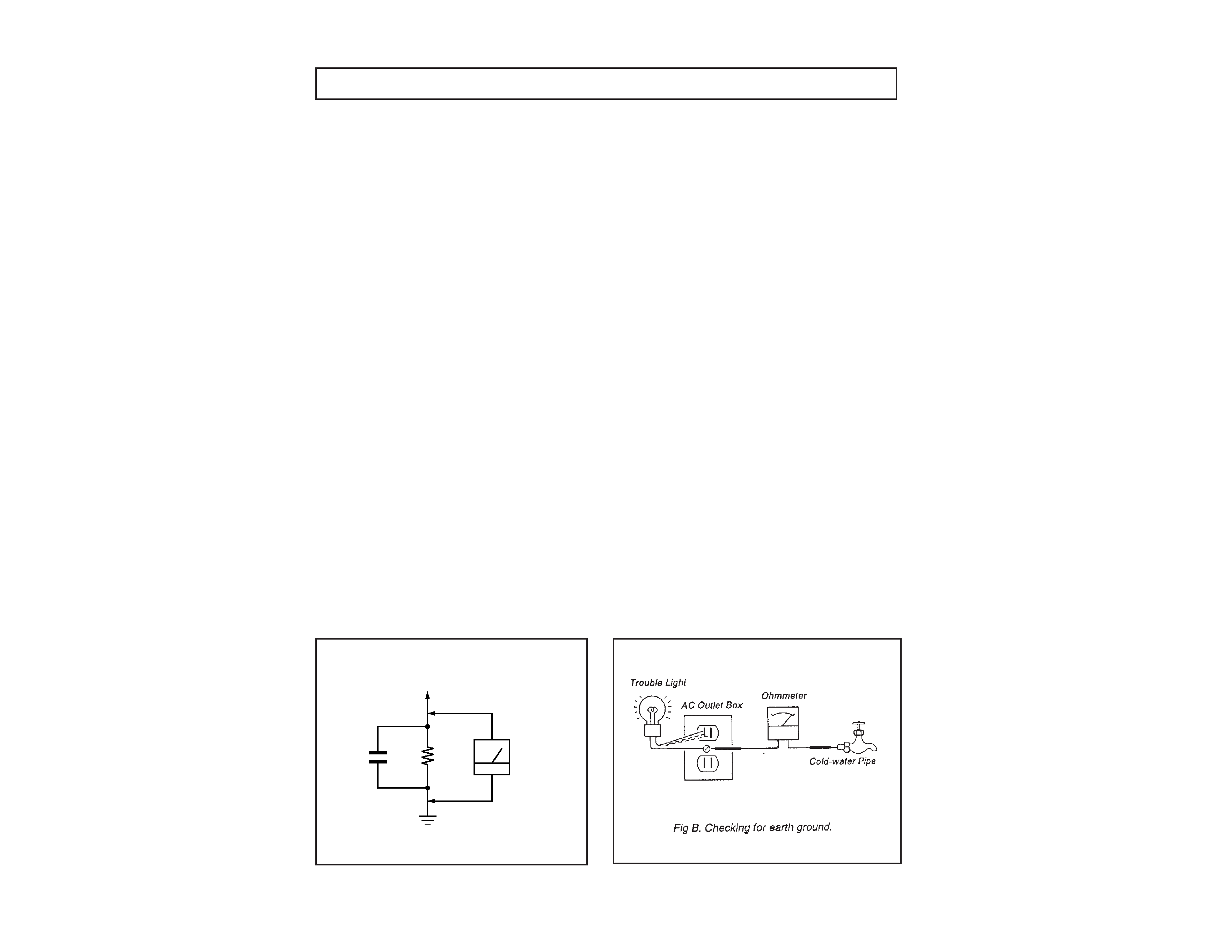
LEAKAGE TEST
The AC leakage from any exposed metal part to earth ground
and from all exposed metal parts to any exposed metal part having
a return to chassis, must not exceed 0.5 mA (500 microampere).
Leakage current can be measured by any one of three methods.
1. A commercial leakage tester, such as the Simpson 229 or
RCA WT-540A. Follow the manufacturers' instructions to
use these instructions.
2. A battery-operated AC milliammeter. The Data Precision
245 digital multimeter is suitable for this job.
3. Measuring the voltage drop across a resistor by means of
a VOM or battery-operated AC voltmeter. The "limit"
indication is 0.75 V, so analog meters must have an accurate
low voltage scale. The Simpson's 250 and Sanwa
SH-63Trd are examples of passive VOMs that are suitable.
Nearly all battery operated digital multimeters that have a
2V AC range are suitable. (See Fig. A)
1. Check the area of your repair for unsoldered or poorly-
soldered connections. Check the entire board surface
for solder splashes and bridges.
2. Check the interboard wiring to ensure that no wires
are "pinched" or contact high-wattage resistors.
3. Check that all control knobs, shields, covers, ground
straps, and mounting hardware have been replaced.
Be absolutely certain that you have replaced all the
insulators.
4. Look for unauthorized replacement parts, particularly
transistors, that were installed during a previous
repair. Point them out to the customer and
recommend their replacement.
5. Look for parts which, though functioning, show
obvious signs of deterioration. Point them out to
the customer and recommend their replacement.
6. Check the line cords for cracks and abrasion.
Recommend the replacement of any such line cord
to the customer.
7. Check the B+ and HV to see if they are specified
values. Make sure your instruments are accurate;
be suspicious of your HV meter if sets always have
low HV.
8. Check the antenna terminals, metal trim, "metallized"
knobs, screws, and all other exposed metal parts for
AC Leakage. Check leakage as described below.
HOW TO FIND A GOOD EARTH GROUND
A cold-water pipe is guaranteed earth ground; the cover-plate
retaining screw on most AC outlet boxes is also at earth ground.
If the retaining screw is to be used as your earth-ground, verify
that it is at ground by measuring the resistance between it and a
cold-water pipe with an ohmmeter. The reading should be zero
ohms. If a cold-water pipe is not accessible, connect a 60-l00 watts
trouble light (not a neon lamp) between the hot side of the re-
ceptacle and the retaining screw. Try both slots, if necessary, to
locate the hot side of the line, the lamp should light at normal
brilliance if the screw is at ground potential. (See Fig. B)
1.5 k
0.15 µF
AC
Voltmeter
(0.75 V)
To Exposed Metal
Parts on Set
Earth Ground
Fig. A. Using an AC voltmeter to check AC leakage.
--
5
--
KV
-32XBR200/KV
-36XBR200
TV/VIDEO
(page 16)
ANT (page 16)
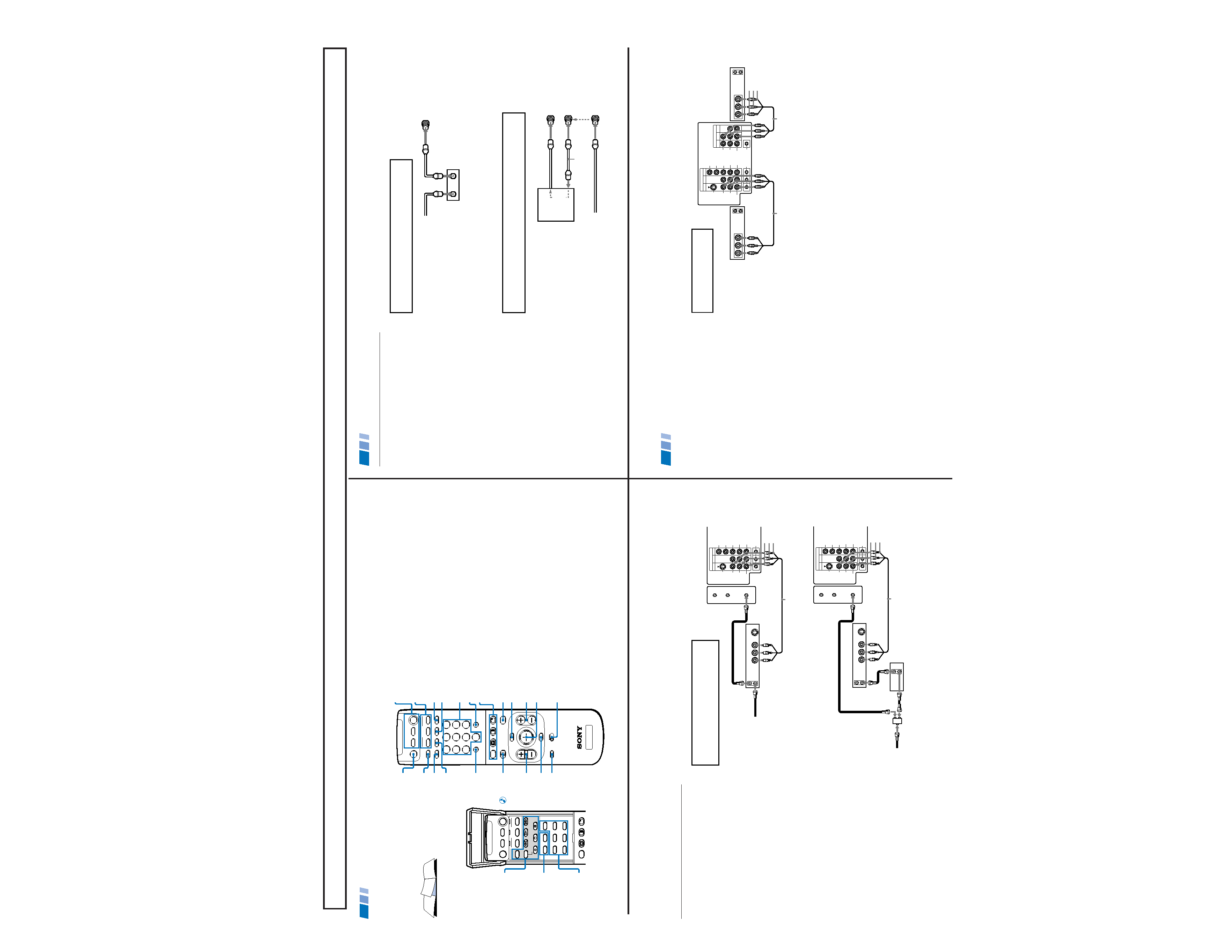
In the instructions that follow, we will
refer to the buttons on your remote control.
Keep this flap unfolded and use this page
for reference.
Getting to know the buttons on the
remote control
Names of the buttons on the remote
control are presented in different colors to
represent the available functions.
Button color
Black ................ Press to select the component
you want to control; e.g. VTR
(VCR)/MDP/DVD Player, DBS
(Direct Broadcast Satellite)/
CABLE, or TV
Green ............... Buttons relevant to power
operations, like turning the TV,
DBS (Direct Broadcast Satellite)/
CABLE, or VTR (VCR)/MDP/
DVD Player on or off
Label color
White ............... TV/VTR (VCR)/MDP/DVD
Player/DBS (Direct Broadcast
Satellite)/CABLE operation
buttons
Yellow .............. PIP, P&P, and CHANNEL
INDEX operation buttons
Blue .................. DBS (Direct Broadcast Satellite)
operation buttons
Green ............... S-Link operation buttons
Pink .................. DVD Player operation buttons
For a detailed explanation of most buttons, see
"Watching the TV" on page 15.
Remote Control
MUTING
(page 15)
POWER
(page 15)
FUNCTION
(page 15)
ENTER
0 9 Buttons
MTS/GUIDE
PIP/P&P/
CHANNEL INDEX
(pages 17-20)
VTR1/2/3/DVD/
MDP (page 31)
Joystick
(page 13)
CH +/
MENU
RESET
VOL +/
TV/DBS
JUMP
(page 15)
DISPLAY (page 16)
SLEEP (page 15)
SYSTEM OFF (page 16)
MTS
TV
MUTING
VTR/DVD DBS/CABLE
POWER
VTR/DVD DBS/CABLE
FUNCTION
TV
TITLE
DVD MENU
FREEZE
AUDIO
SWAP
CH +
POSITION
TV/VIDEO
CH -
TV/VTR
REC
GUIDE
TV/DBS
OFF
TV
2
13
5
46
8
79
0
TV
MTS
MUTING
VTR/DVD DBS/CABLE
POWER
VTR/DVD DBS/CABLE
FUNCTION
TV
OFF
SYSTEM
SLEEP
DISPLAY
TV/VIDEO
ANT
MENU
GUIDE
VOL
TV/DBS
RESET
CH
VTR 1 2 3 DVD/MDP
CODE SET
JUMP
ENTER
OFF
RM-Y144
PIP/P&P
(pages 17, 18)
DVD
Operation
Buttons
(page 32)
VCR/DVD/MDP
Operation
Buttons
(page 32)
CODE SET
(pages 31, 33)
If you are connecting a cable box through the AUX input and would like
to switch between the AUX and normal (CATV) input you should consider
using the CHANNEL FIX feature. (see "CHANNEL SET UP" on page 26)
If you will be controlling all channel selection through
your cable box, you should consider using the CHANNEL
FIX feature. (see "CHANNEL SET UP" on page 26)
Cable Box Connections
Some pay cable TV systems use scrambled or
encoded signals that require a cable box to
view all channels.
Cable box
1 Connect the coaxial connector from your
cable to the IN on your cable box.
2 Using a coaxial cable, connect OUT on
your cable box to VHF/UHF on your TV.
Cable box and cable
For this set up, you can switch between
scrambled channels (through your cable box),
and normal (CATV) channels by pressing
ANT on your remote control.
Notes
· Your Sony remote control can be
programmed to operate your cable box.
(see "Operating a Cable Box or DBS
Receiver" on page 33)
· When using PIP, you cannot view the
AUX input in the window picture.
Tip
z
Pressing ANT switches between these inputs.
Cable box
Cable
OUT
IN
(Rear of TV)
VHF/UHF
TO CONVERTER
Cable box
VHF/UHF
(Rear of TV)
AUX
75-ohm coaxial
cable (not supplied)
CATV cable
(unscrambled channels)
(signal)
scrambled
channels
Connecting and Installing the TV (continued)
4
SECTION 1
GENERAL
VIDEO IN
13
4
L
R
(MONO)
VIDEO
S VIDEO
OUT
AUDIO
L
R
Y
PB
PR
AUDIO
S-LINK
CONTROL S
AUX
TO
CONVERTER
VHF/UHF
AUDIO R AUDIO L VIDEO
S VIDEO
LINE
OUT
OUT
IN
Disconnect all power sources before making any connections.
VCR Connections
Connecting an antenna/cable TV
system with a VCR
1 Attach the coaxial connector from your
cable or antenna to IN on your VCR.
2 Using A/V connectors, connect AUDIO
and VIDEO OUT on your VCR to AUDIO
and VIDEO IN on your TV*.
3 Using a coaxial connector, connect OUT on
your VCR to VHF/UHF on your TV.
* If you are connecting a monaural VCR, connect only the
single white audio output to the left input on your TV.
Connecting a VCR and TV with a
cable box
1 Connect the single (input) jack of the
splitter to your incoming cable connection,
and connect the other two (output) jacks
(using coaxial cable) to IN on your cable
box and VHF/UHF on your TV.
2 Using a coaxial connector, connect OUT on
your cable box to IN on your VCR.
3 Using A/V connectors, connect AUDIO and
VIDEO OUT on your VCR to AUDIO and
VIDEO IN on your TV.
Coaxial cable
(Rear of TV)
VMC-810S/820S (not supplied)
Cable
VCR
3
1
2
AUDIO-R (red)
AUDIO-L (white)
VIDEO (yellow)
For optimum picture quality, use S VIDEO
instead of the yellow A/V cable. S VIDEO does
not provide sound, your audio connectors
must still be connected.
VIDEO IN
13
4
L
R
(MONO)
VIDEO
S VIDEO
OUT
AUDIO
L
R
Y
PB
PR
AUDIO
S-LINK
CONTROL S
AUX
TO
CONVERTER
VHF/UHF
AUDIO R AUDIO L VIDEO
S VIDEO
LINE
OUT
OUT
IN
OUT
IN
(Rear of TV)
VMC-810S/820S (not supplied)
Cable box
Splitter
(not supplied)
3
AUDIO-R (red)
AUDIO-L (white)
VIDEO (yellow)
VCR
Cable
Coaxial cable
2
1
5
OUT
MONITOR AUDIO
(VAR/FIX)
TV
VIDEO IN
13
4
IN
L
R
(MONO)
VIDEO
VIDEO
S VIDEO
OUT
AUDIO
L
R
(MONO)
AUDIO
L
R
Y
PB
PR
AUDIO
S-LINK
CONTROL S
LINE
OUT
OUT
IN
LINE
IN
OUT
IN
AUDIO R AUDIO L VIDEO
AUDIO R AUDIO L VIDEO
Disconnect all power sources before making any connections.
Connecting two VCRs
MONITOR OUT gives you the ability to use a
second VCR to record a program being played
by the primary VCR or to perform tape
editing and dubbing.
1 Connect the VCR intended for playback
using the connection instructions on page
4 of this manual.
2 Using A/V connectors, connect AUDIO
and VIDEO IN on your VCR intended for
recording to MONITOR AUDIO and
VIDEO OUT on your TV.
VCR (for playback)
VCR (for recording)
VMC-810S/820S (not supplied)
VMC-810S/820S (not supplied)
(Rear of TV)
1
2
Do not change the input
signal while editing through
MONITOR OUT.
Connecting and Installing the TV (continued)
AUDIO-R (red)
AUDIO-L (white)
VIDEO (yellow)
6
The instructions mentioned here are partial abstracts from the Operating Instruction Manual. The page numbers showm reflect those of the Operating Instruction Manual.