SERVICEMANUAL
RM-Y102
US Model
KV-27TW75
Chassis No.
KV-27TW76
Chassis No.
Canadian Model
KV-27TW75
Chassis No.
KV-27TW76
Chassis No.
(Natural wood finish)
(Black)
Television system American TV standards
Channel coverage
VHF: 2
13
UHF:
14-69
Picture
tube
Antenna
Input
Cable TV: 1
125
tube
picture measured diagonally
picture tube measured
diagonally
external antenna terminal
VHF/UHF
VIDEO and S VIDEO
S VIDEO IN (S terminal)
Y: 1 Vp-p, 75-ohms
unbalanced,
sync
negative
C: 0.286 Vp-p (Burst signal),
Video (phono jacks): 1 Vp-p,
unbalanced,
sync
negative
output
Audio (phono jacks): 500
(100% modulation)
Impedance: 47 kilohms
AUDIO
OUT
(VARIABLE)
(phono
jacks)
More than 408
at the
maximum
volume
setting
(variable)
Impedance: 5 kilohms
MODELS OF THE SAME SERIES
SPECIFICATIONS
Speaker output
Audio Power: 5 watts/channel minimum continuous
power, 2 channels driven into 8 ohms from
to 20kHz with
or less THD, mea-
sured from auxiliary input to load
Power
requirements
120 V AC,
Power consumption
170w
5W Standby mode
Dimensions
h
d)
758.0 x 100.0 x 635.0 mm
(29% x 39% x 25 in.)
88 6 kg
(195 Ibs 6 oz)
Supplied accessories
Remote commander RM-Y102 (1) with 2 size AA
(R6) EVEREADY batteries
.
Recommended
accessories
UN mixer EAC-66
Connecting cable
YC-15
V, RK-74A
Design
and
specifications
are
subject
to
change
without
notice.
TV
(CAUTION)
SHORT CIRCUIT THE ANODE OF THE PICTURE TUBE AND THE
ANODE CAPTOTHE METAL CHASSIS, CRTSHIELD, OR CARBON
PAINTED ON THE CRT, AFTER REMOVING THE ANODE.
WARNING!!
AN
ISOLATION
TRANSFORMER
SHOULD
BE
USED
DURING
ANY SERVICE TO AVOID POSSIBLE SHOCK HAZARD, BECAUSE
OF LIVE CHASSIS.
THE CHASSIS OF THIS RECEIVER IS DIRECTLY CONNECTED
TO THE AC POWER LINE.
SAFETY-RELATED
COMPONENT
WARNING
!!
COMPONENTS IDENTIFIED BY SHADING AND MARK
SCHEMATIC DIAGRAMS,
PARTS
LIST ARE CRITICAL TO SAFE OPERATION. REPLACE THESE
COMPONENTS WITH SONY PARTS WHOSE PART NUMBERS
APPEAR AS SHOWN IN THIS MANUAL OR IN SUPPLEMENTS
PUBLISHED
BY
SONY.
CIRCUIT
ADJUSTMENTS
THAT
ARE
CRITICAL
TO
SAFE
OPERATION
ARE
IDENTIFIED
IN
THIS
MANUAL.
FOLLOW
THESE
PROCEDURES
WHENEVER
CRITI-
CAL COMPONENTS ARE REPLACED OR IMPROPER OPERA-
TION IS SUSPECTED.
(ATTENTION)
APRES
DECONNECTE
LE
CAP
DE
L'ANODE,
L'ANODE DU TUBE CATHODIQUE ET
DE L'ANODE DU CAP AU CHASSIS
DE L'APPAREIL,
OU AU COUCHE DE
SUR LE TUBE
CATHODIQUE OU AU
DU TUBE CATHODIQUE.
ATTENTION!!
TOUT RISQUE D'ELECTROCUTION PROVENANT
D'UN
TENSION, UN TRANSFORMATEUR
D'ISOLEMENT
ETRE
LORS DETOUT DEPANNAGE.
LE
DE CE
EST
L'ALIMENTATION SECTEUR.
ATTENTION AUX COMPOSANTS
LES
PAR UNE TRAME ET PAR UNE
A SUR LES
DE PRINCIPE, LES VUES
ET LES
DE PIECES CONT D'UNE
IMPORTANCE
CRITIQUE
POUR
LA
DU
FONCTIONNEMENT.
NE
LES
REMPLACER
QUE
PAR
DES
COMPOSANTSSONY DONT
DE
EST
DANS LE
MANUEL OU DANS DES SUPPLEMENTS
PAR
SONY.
LES
DE CIRCUIT DONT
L'IMPORTANCE EST CRITIQUE POUR LA
DU
FONCTIONNEMENT
SONT
IDENTIFIES
DANS
LE
MANUEL.
CES
LORS
DE
CHAQUE
REMPLACEMENT
DE
COMPOSANTS
CRITIQUES,
OU
LORSQU'UN
FONCTIONNEMENT EST
SAFETY CHECK-OUT
(US Model only)
Aftercorrecting theoriginalserviceproblem, performthefollowing
LEAKAGE
safety checks before releasing the set to the customer:
2
3
4
6
7.
8.
9.
Check the area of your repair for unsoldered or poorly-soldered
connections. Check the entire board surface for solder splashes
and bridges
Check the interboard wiring
that no wires are "pinched"
or
contact
high-wattage
resistors.
Check that all control knobs, shields, covers, ground straps, and
mounting hardware have been replaced Be absolutely certain that
you have replaced all the insulators.
Look
for
unauthorized
replacement
parts,
particularly
transistors,
that were installed during a previous repair Point them out to the
customer and recommend their replacement
Look for parts which, though functioning, show obvious signs of
deterioration. Point them out to the customer and recommend
their replacement.
Check the line cord for cracks and abrasion. Recommend the
replacement of any such line cord to the customer
Check the condition of the
antenna (if any)
Make sure the end is not broken off, and has the plastic cap on it.
Point out the danger of impalement on a broken antenna to the
customer, and recommend the antenna's replacement
Check the B+ and HV to see they are at the values specified. Make
sure your instruments are accurate, be suspicious of your HV
meter if sets always have low HV
Check the antenna terminals, metal trim,
knobs,
screws, and all other exposed metal parts for AC leakage Check
leakage as described below
To Exposed Metal
Parts on Set
0
AC
voltmeter
(0
Earth Ground
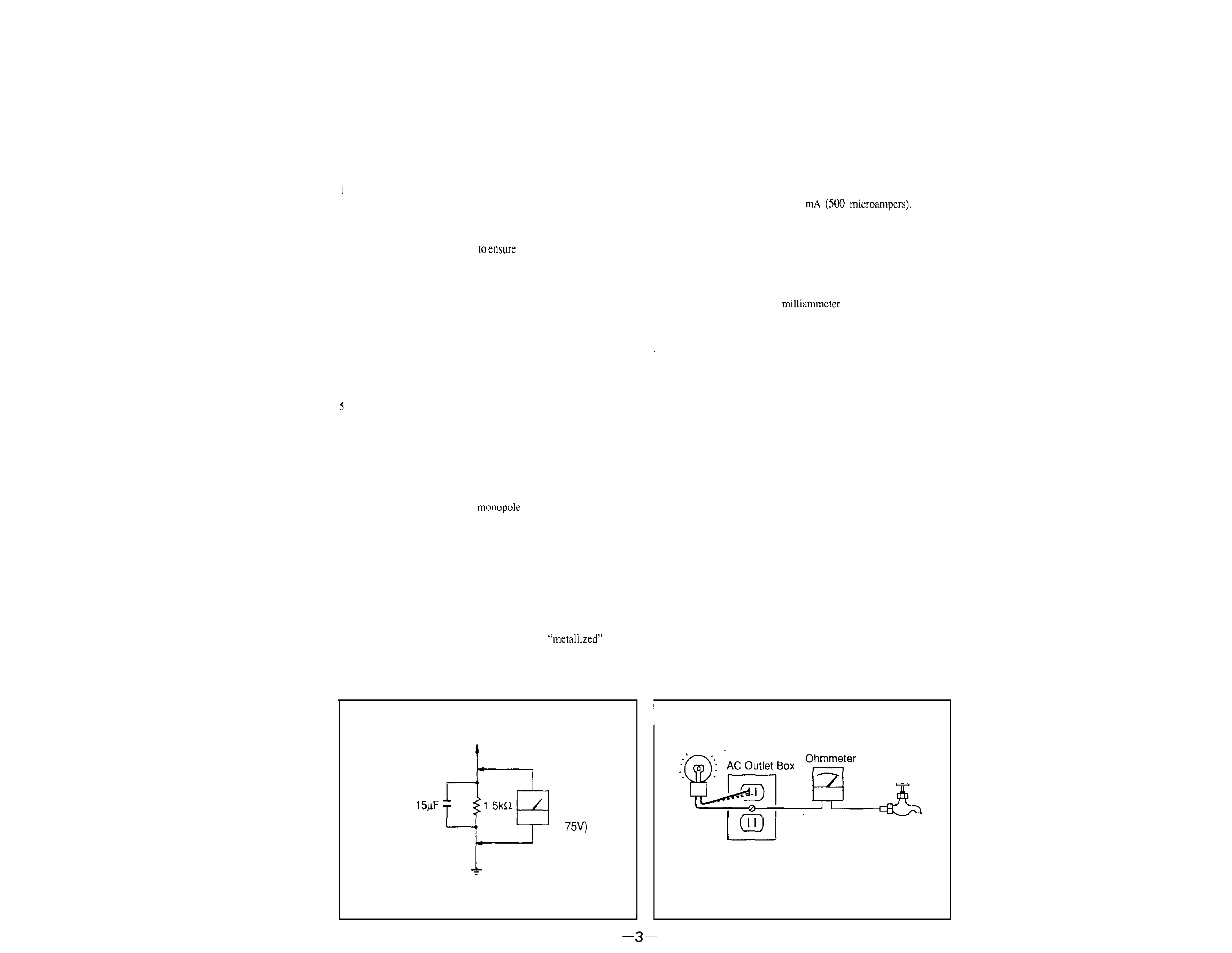
Fig A. Using an AC voltmeter to check AC leakage
Fig B Checking for earth ground.
The AC leakage from any exposed metal part to earth ground and
from all exposed metal parts to any exposed metal part having a return
to chassis, must not exceed 0.5
Leakage
current can be measured by any one of three methods.
1.
A commercial leakage tester, such as the Simpson 229 or RCA
WT-540A Follow the manufacturers' instructions to use these
instruments
2
A battery-operated AC
The Data Precision 245
digital multimeter is suitable for this job
3 .
Measuring the voltage drop across a resistor by means of a VOM
or battery-operated AC voltmeter The "limit" indication is 0.75
V, so analog meters must have an accurate low-voltage scale. The
Simpson 2.50 and Sanwa SH-63Trd are examples of a passive
VOM that is suitable. Nearly all battery operated digital multimeters
that have a 2V AC range are suitable (See Fig. A)
HOW TO FIND A GOOD EARTH GROUND
A cold-water pipe is guaranteed earth ground; the cover-plate
retaining screw on most AC outlet boxes is also at earth ground If the
retaining screw is to be used as your earth-ground, verify that it is at
ground by measuring the resistance between it and a coldwater pipe
with an ohmmeter. The reading should be zero ohms. If a cold-water
pipe is not accessible, connect a 60-100 watts trouble light (not a neon
lamp) between the hot side of the receptacle and the retaining screw.
Try both slots, if necessary, to locate the hot side of the line, the lamp
should light at normal brilliance if the screw is at ground potential. (See
Fig B)
Trouble Light
Cold-water
Pipe
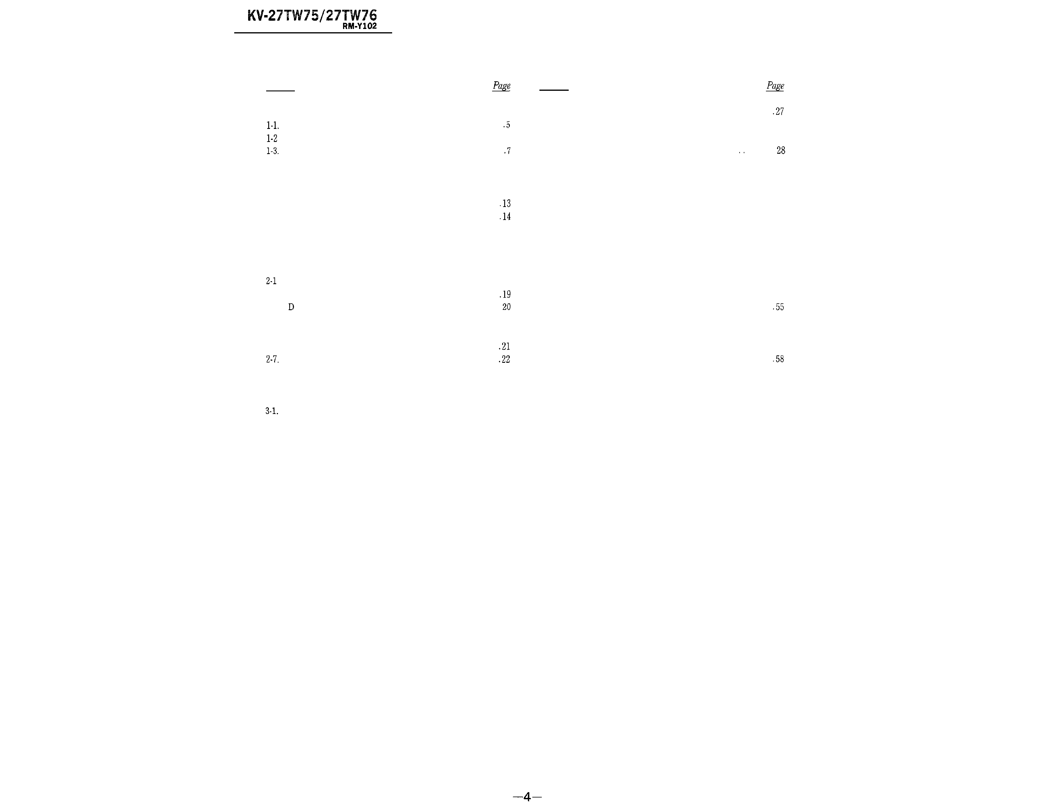
TABLEOFCONTENTS
Section
Title
1. GENERAL
Locating the Controls
...............
Connecting
TV
Antenna/Cable ...... 7
Turning the Cable Mode On or Off
...........
1-4. Presetting TV Channels
........
8
1-5. Using Picture-in-Picture .
.
10
1.6. Using the Pre-Programmed Remote Commander
12
l-7. Setting the CURRENT TIME .......
l-8. Using the Timer-activated Functions-GUIDE
...
l-9. Using CHANNEL CAPTION
.......
. .
17
l-10. Enjoying Other Useful Features
....
18
2.
DISASSEMBLY
Rear Plate Removal
......
19
2-2. Service Position
..................
2-3.
Board Removal ....................
2-4. Antenna Terminal Board Removal
...
20
2-5.
B, A and E Boards Removal ...............
21
2-6.
How to Improve Interlace
.
..............
B, A and E Boards Service Position ............
2-8. Picture Tube Removal
.........
23
3. SET-UP ADJUSTMENTS
Beam Landing
.................
3-2.
Convergence
........................
24
25
Section
Title
3-3
Focus Adjustment . . . . . . . . . .
3-4. White Balance
. . . .
4. SAFETY RELATED ADJUSTMENTS
. .
. . . . . . . 27
5. CIRCUIT ADJUSTMENTS
5-l
A Board Adjustments .
. . . . . .
5-2 B Board Adjustments
5-3. D Board Adjustments
5-4.
E Board Adjustments . .
. .
30
.
.
30
.
31
32
6. DIAGRAMS
6-1. Block Diagram
. . . . . . . .
6-2. Circuit Boards Location
. . .
6-3.
Printed Wiring Boards and Schematic Diagrams
6-4. Semiconductors .
. . . . . . . . . . . .
33
. . . . .
37
37
7. EXPLODED VIEWS
7-l. Cover . . . . .
. . . . . . . . .
. . . .
7-2. Chassis .
. . . .
. . . . . .
7-3.
Picture
Tube
.
.
. . .
8. ELECTRICAL PARTS LIST
60
57
59
SECTION 1
GENERAL
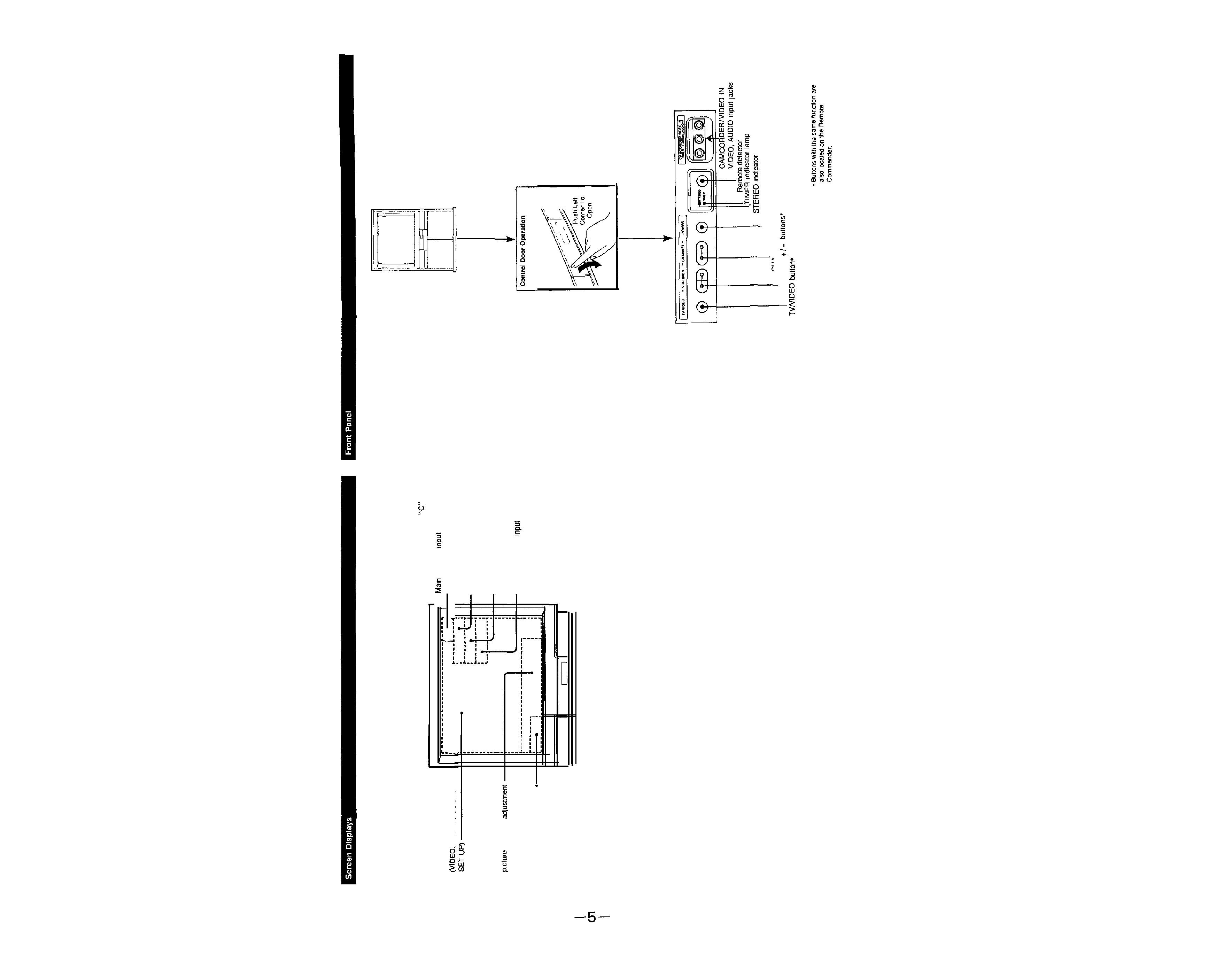
1-1. LOCATING THE CONTROLS
Channel number/cable
displays
A/V WINDOW displays
AUDIO. GUIDE.
Picture
mode
l
:
, ,
SLEEP, MUTING displays
Bar display for volume,
or sound
CURRENT TIME display
SURROUND display
CHANNEL CAPTION display
MTS mode (MAIN, SAP or
MONO)
Picture-m-Picture
mode
,
lamp
POWER button*
CHANNEL +I- buttons*
VOLUME