1
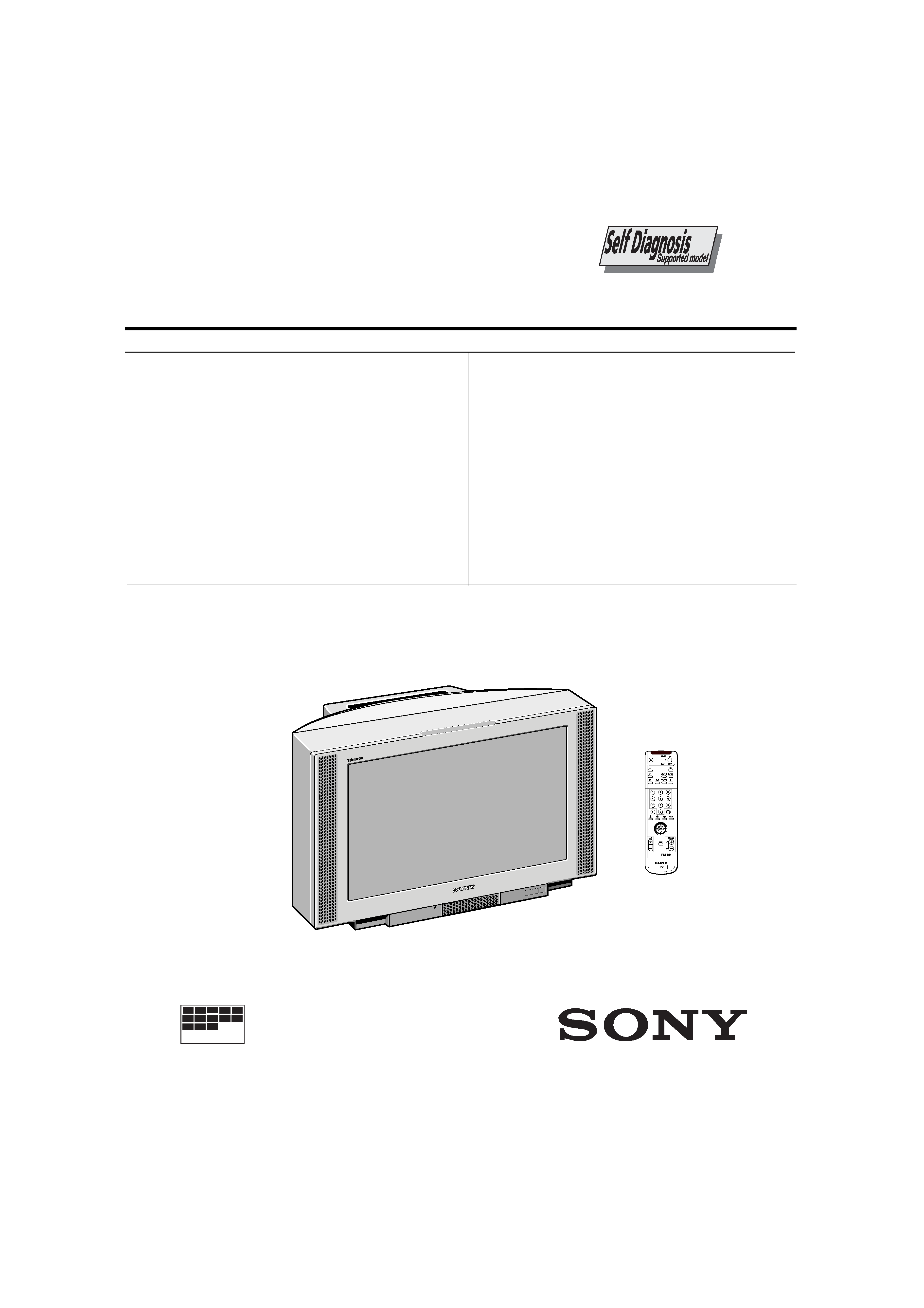
SERVICE MANUAL
AE-5 CHASSIS
MODEL
COMMANDER
DEST
CHASSIS NO.
MODEL
COMMANDER
DEST
CHASSIS NO.
®
KV-29FS60A RM-891 Italian SCC-Q12E-A
KV-29FS60B RM-891 French SCC-Q13E-A
KV-29FS60D RM-891 AEP SCC-Q11E-A
KV-29FS60E RM-891 Spanish SCC-Q14E-A
KV-29FS60K RM-891 OIRT SCC-Q16G-A
KV-29FS60R RM-891 OIRT SCC-Q16H-A
KV-29FS60U RM-891 UK SCC-Q15D-A
KV-32FS60A RM-891 Italian SCC-Q12F-A
KV-32FS60B RM-891 French SCC-Q13F-A
KV-32FS60D RM-891 AEP SCC-Q11F-A
KV-32FS60E RM-891 Spanish SCC-Q14F-A
MICR OFILM
TRINITRON ® COLOR TV
2
[PICTURE TUBE]
KV-29FS60
FD Trinitron
Approx. 72 cm (29 inches)
(Approx. 68 cm picture measured
diagonally)
102 degree deflection
KV-32FS60
FD Trinitron
Approx. 82 cm (32 inches)
(Approx. 76 cm picture measured
diagonally)
102 degree deflection
Input/Output Terminals
[REAR]
21-pin Euro connector (CENELEC standard).
-
Inputs for Audio and Video signals.
-
Inputs for RGB.
-
Outputs of TV Video and Audio signals.
21-pin Euro connector
-
Inputs for Audio and Video signals.
-
Inputs for S video.
-
Outputs forVideo and Audio signals (selectable).
21-pin Euro connector
-
Inputs for Audio and Video signals.
-
Inputs for S video.
External speaker terminals : 2-pin DIN (5)
[FRONT]
3 Video output - phono jack
3 Audio inputs - phono jacks
3 S Video input - 4 pin DIN
Headphone jack : stereo minijack
Sound output
2x25W (Music Power)
Power requirements
220 - 240V
Dimensions
KV-29FS60
Approx 738 x 588 x 507 mm (w/h/d)
KV-32FS60
Approx 867 x 564 x 558 mm (w/h/d)
Weight
KV-29FS60
Approx 55kg
KV-32FS60
Approx 68kg
Supplied accessories
RM-891 Remote Commander (1)
IEC designated R6 battery (2)
Other features
NICAM*, FASTEXT, TOPTEXT
* (KV-29FS60B/29FS60E/29FS60K/
29FS60U/32FS60B/32FS60E only)
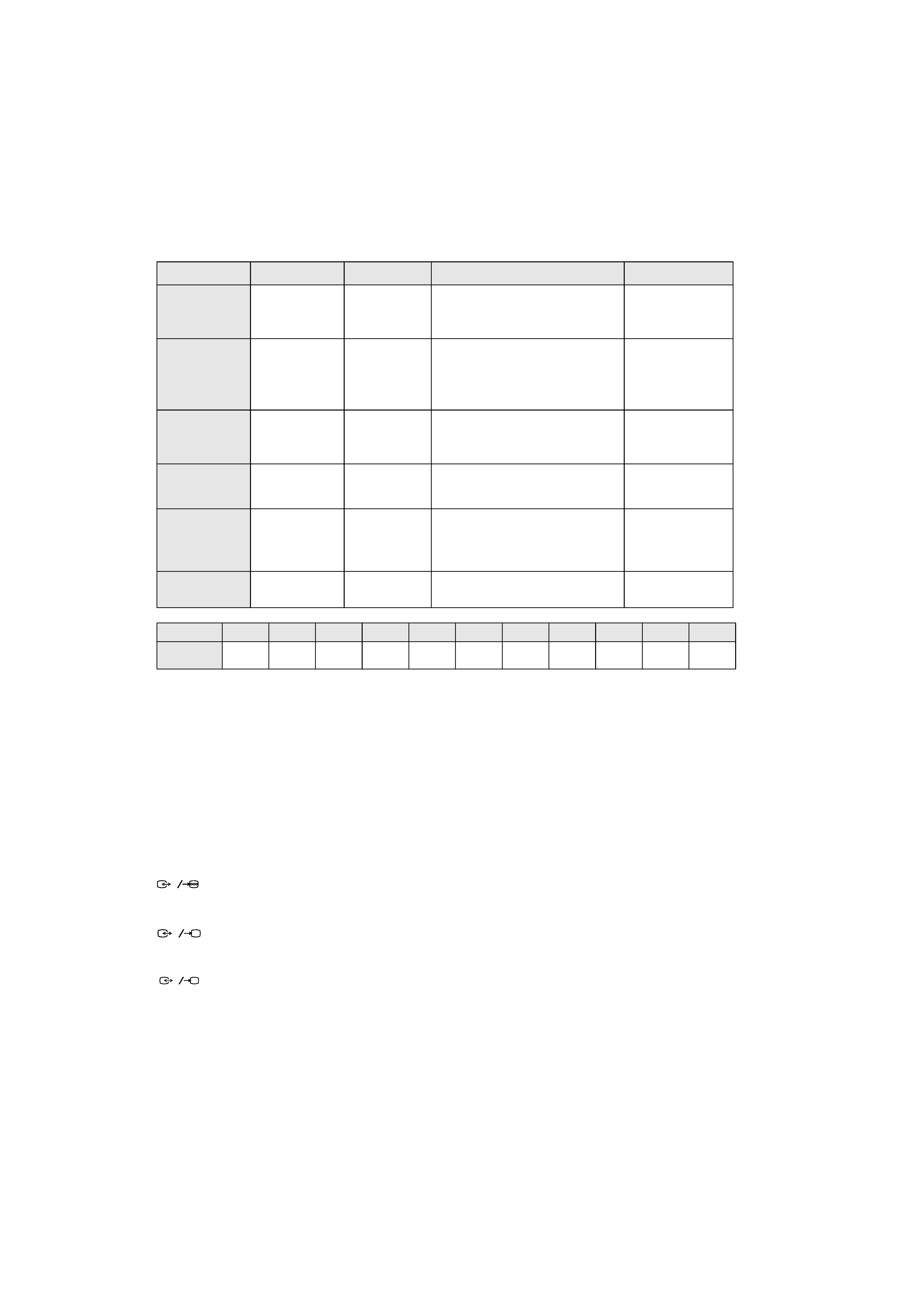
ITEM MODEL
Television System
Stereo System
Channel Coverage
Color System
Italian
B/G/H,D/K
GERMAN Stereo
ITALIA VHF : A-H2 (C) UHF : 21-69 PAL
B/G/H VHF : E2-E12 UHF : E21-E69
CABLE TV (1) : S1-S41
CABLE TV (2) : S01-S05,M1-M10,U1-U10
DK VHF : R01-R12 UHF : R21-R69
PAL, SECAM
NTSC4.43, NTSC3.58
(VIDEO IN)
French
B/G/H, D/K,L,I
GERMAN/NICAM
Stereo
L VHF : F02-F10 UHF : F21-F60
CABLE : B-Q B/G/H VHF : E2-E12
UHF : E21-E69
CABLE TV (1) : S1-S41
CABLE TV (2) : S01-S05, M1-M10, U1-U10
ITALIA VHF : A-H2 (C) UHF : 21-69
I UHF : B21-B69
PAL, SECAM
NTSC4.43, NTSC3.58
(VIDEO IN)
AEP
B/G/H, D/K
GERMAN Stereo
PAL B/G/H/ VHF : E2-E12 : E21-E69
CABLE TV (1) : S1-S41
CABLE TV (2) : S01-S05, M1-M10, U1-U10
ITALIA VHF : A-H2 (C) UHF : 21-69
D/K VHF : R01-R12 UHF : R21-R69
PAL, SECAM
NTSC4.43, NTSC3.58
(VIDEO IN)
Spanish
B/G/H, D/K
GERMAN/NICAM
Stereo
PAL B/G/H/ VHF : E2-E12 : E21-E69
CABLE TV (1) : S1-S41
CABLE TV (2) : S01-S05, M1-M10, U1-U10
ITALIA VHF : A-H2 (C) UHF : 21-69
PAL, SECAM
NTSC4.43, NTSC3.58
(VIDEO IN)
OIRT
B/G/H, D/K
KV-29FS60K
GERMAN/NICAM
Stereo
KV-29FS60R
GERMAN Stereo
B/G/H/ VHF : E2-E12 UHF : E21-E69
CABLE TV (1) : S1-S41
D/K VHF : R01-R12 UHF : R21-R69
PAL, SECAM
NTSC4.43, NTSC3.58
(VIDEO IN)
UK
I
NICAM Stereo
UHF : B21-B69
PAL
NTSC4.43, NTSC3.58
(VIDEO IN)
MODEL
29FS60A
29FS60B
29FS60D
29FS60E
29FS60K
29FS60R
29FS60U
32FS60A
32FS60B
32FS60D
32FS60E
Power
Consumption
149Wh
148Wh
148Wh
148Wh
148W
148W
148Wh
144Wh
149Wh
149Wh
149Wh
1
2
S
3
S
3
WARNING (KV-29FS60U only)
The flexible mains lead is supplied connected to a B.S. 1363 fused plug
having a fuse of 5 AMP capacity. Should the fuse need to be replaced,
use a 5 AMP FUSE approved by ASTA to BS 1362, ie one that carries the
mark.
IF THE PLUG SUPPLIED WITH THIS APPLIANCE IS NOT SUITABLE
FOR THE OUTLET SOCKETS IN YOUR HOME, IT SHOULD BE CUT
OFF AND AN APPROPRIATE PLUG FITTED. THE PLUG SEVERED
FROM THE MAINS LEAD MUST BE DESTROYED AS A PLUG WITH
BARED WIRES IS DANGEROUS IF ENGAGED IN A LIVE OUTLET
SOCKET.
When an alternative type of plug is used it should be fitted with a 5 AMP
FUSE, otherwise the circuit should be protected by a 5 AMP FUSE at the
distribution board.
ASA
T
How to replace the fuse.
Open the fuse compartment with
a screwdriver blade and replace
the fuse.
FUSE
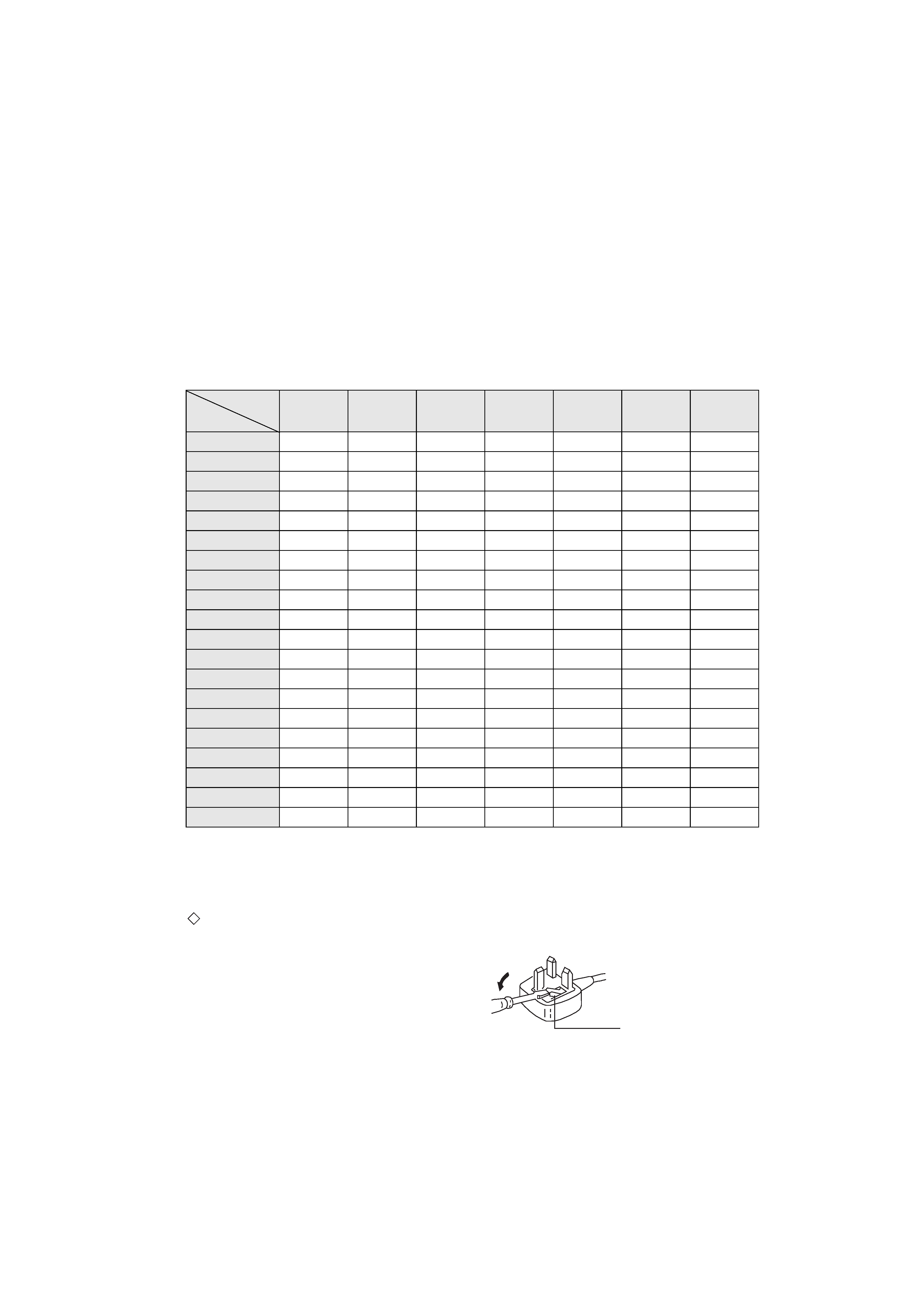
Model Name
Item
KV-29FS60A
KV-32FS60A
KV-29FS60B
KV-32FS60B
KV-29FS60D
KV-32FS60D
KV-29FS60E
KV-32FS60E
KV-29FS60K
KV-29FS60R
KV-29FS60U
Pal Comb
ON
ON
ON
ON
ON
ON
ON
PIP
OFFOFF
OFFOFF
OFFOFF
OFF
RGB Priority
ON
ON
ON
ON
ON
ON
ON
Woofer Box
OFFOFF
OFFOFF
OFFOFF
OFF
Scart 1
ON
ON
ON
ON
ON
ON
ON
Scart 2
ON
ON
ON
ON
ON
ON
ON
Front in (3)
ON
ON
ON
ON
ON
ON
ON
Scart 4
ON
ON
ON
ON
ON
ON
ON
Projector
OFFOFF
OFFOFF
OFFOFF
OFF
AKB in 16:9 mode
ON
ON
ON
ON
ON
ON
ON
Norm B/G
ON
ON
ON
ON
ON
ON
OFF
Norm I
OFF
ON
OFF
OFF
OFF
OFF
ON
Norm D/K
ON
ON
ON
ON
ON
ON
OFF
Norm AUS
OFFOFF
OFFOFF
OFFOFF
OFF
Norm L
OFF
ON
OFF
OFF
OFF
OFF
OFF
Norm SAT
OFFOFF
OFFOFF
OFFOFF
OFF
Norm M
OFFOFF
OFFOFF
OFFOFF
OFF
Teletext
ON
ON
ON
ON
ON
ON
ON
Nicam Stereo
OFF
ON
OFF
ON
ON
OFF
ON
Language Preset
Italian
French
German
Spanish
OIRT
OIRT
English
[RM-891]
Remote control system
Infrared control
Power requirements
3V dc
2 batteries IEC designation
R6 (size AA)
Dimensions
Approx 210x56x24mm (w/h/d)
Weight
Approx 110g (Not including battery)
Design and specifications are subject to change without notice.
4
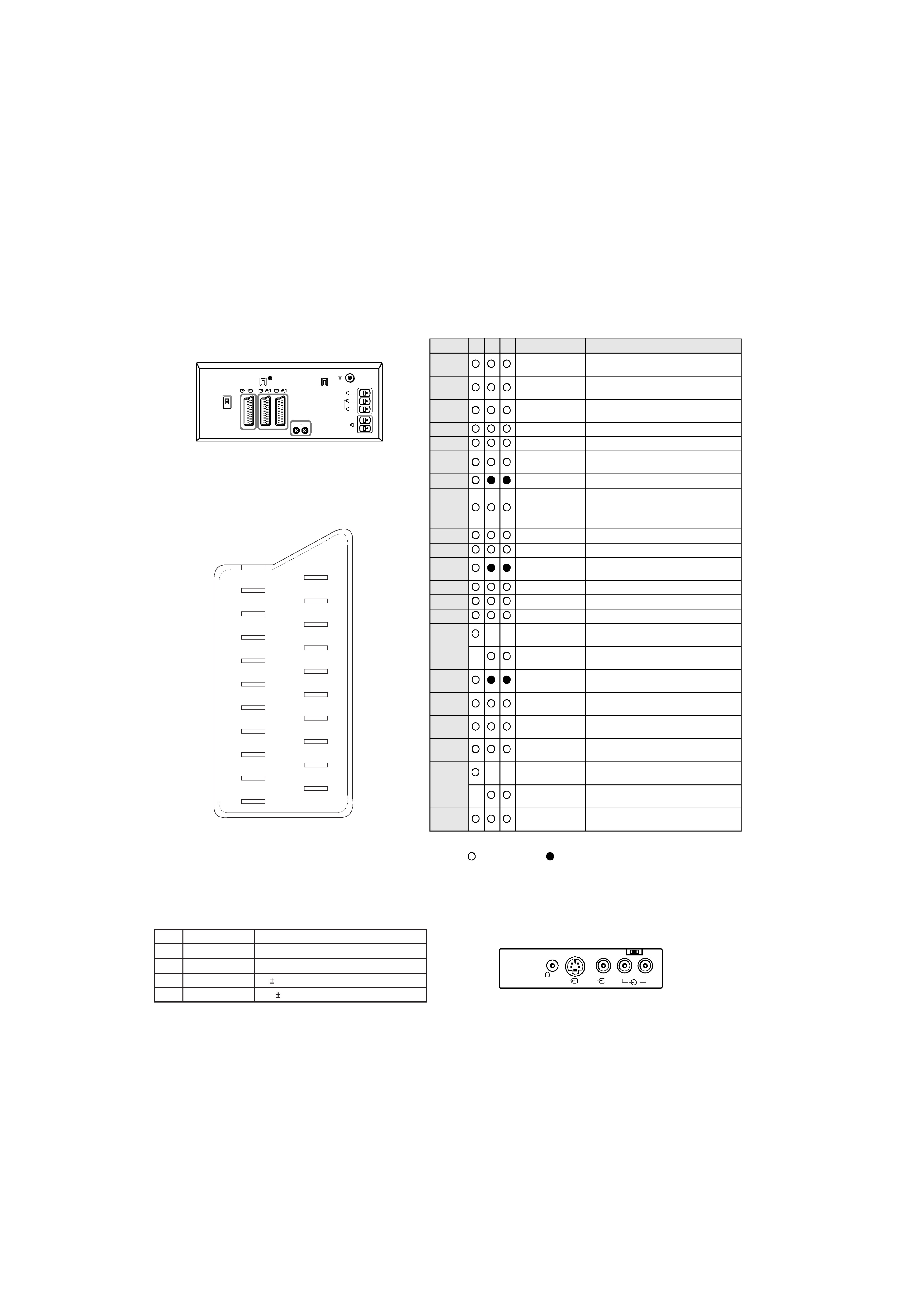
21 pin connector
Connected
Not Connected (open)
* at 20Hz - 20kHz
L/G/S/I
R/D/D/D
S
3
3
3
R/D/D/D
L/G/S/I
R/D/D/D
L/G/S/I
2
S
2
1
3
S
3
1/
S
G
S
19
17
15
13
11
9
7
5
3
1
20
18
16
14
12
10
8
6
4
2
21
Pin No
1
2
4
Signal
Signal level
1
Audio output B
(right)
Standard level : 0.5V rms
Output impedence : Less than 1kohm*
2
Audio output B
(right)
Standard level : 0.5V rms
Output impedence : More than 10kohm*
3
Audio output A
(left)
Standard level : 0.5V rms
Output impedence : Less than 1kohm*
4
Ground (audio)
5
Ground (blue)
6
Audio input A
(left)
Standard level : 0.5V rms
Output impedence : More than 10kohm*
7
Blue input
0.7 +/- 3dB, 75 ohms positive
8
Function select
(AV control)
High state (9.5-12V) : Part mode
Low state (0-2V) : TV mode
Input impedence : More than 10K ohms
Input capacitance : Less than 2nF
9
Ground (green)
10
Open
11
Green
Green signal : 0.7 +/- 3dB, 75 ohms,
positive
12
Open
13
Ground (red)
14
Ground (blanking)
15
_
_
Red input
0.7 +/- 3dB, 75 ohms, positive
_
(S signal Chroma
input)
0.3 +/- 3dB, 75 ohms, positive
16
Blanking input
(Ys signal)
High state (1-3V) Low state (0-0.4V)
Input impedence : 75 ohms
17
Ground (video
output)
18
Ground (video
input)
19
Video output
1V +/- 3dB, 75ohms, positive sync 0.3V
(-3+10dB)
20
_
_
Video input
1V +/- 3dB, 75ohms, positive sync 0.3V
(-3+10dB)
_
Video input
Y (S signal)
1V +/- 3dB, 75ohms, positive sync 0.3V
(-3+10dB)
21
Common ground
(plug, shield)
Signal
Ground
Ground
Y (S signal) input
C (S signal) input
Pin No.
1
2
3
4
Signal Level
1V
3dB 75 ohm, positive Sync. 0.3V -3 + 10dB
0.3V
3dB 75 ohm, positive Sync.
5
AE-5 SELF DIAGNOSTIC SOFTWARE
The identification of errors within the AE-5 chassis is triggered in one of two ways :- 1: Busy or 2: Device failure to respond to IIC. In the event
of one of these situations arising the software will first try to release the bus if busy (Failure to do so will report with continuous flashing LED) and
then communicate with each device in turn to establish if a device is faulty. If a device is found to be faulty the relevant device number will be dis-
played through the LED (Series of flashes which must be counted) See table 1., non fatal errors are reported using this method.
ERROR
LED
ERROR
COUNT
No error
00
Not allowed (may be confused with Sircs response
flash!)
01
Over Current Protection
02
Over Voltage Protection
03
Vertical Protection
04
AKB
05
H - Protection
06
Speaker Protection
07
General IIC Line 0 error
08
MEGATEXT
09
NVM
10
Main colour decoder
11
Feature Box
12
D/A converter
13
Backend
14
Multi sound processor
15
Auto Wide
16
External RAM
17
StBy LED
ON
ON
ON
OFF
OFF
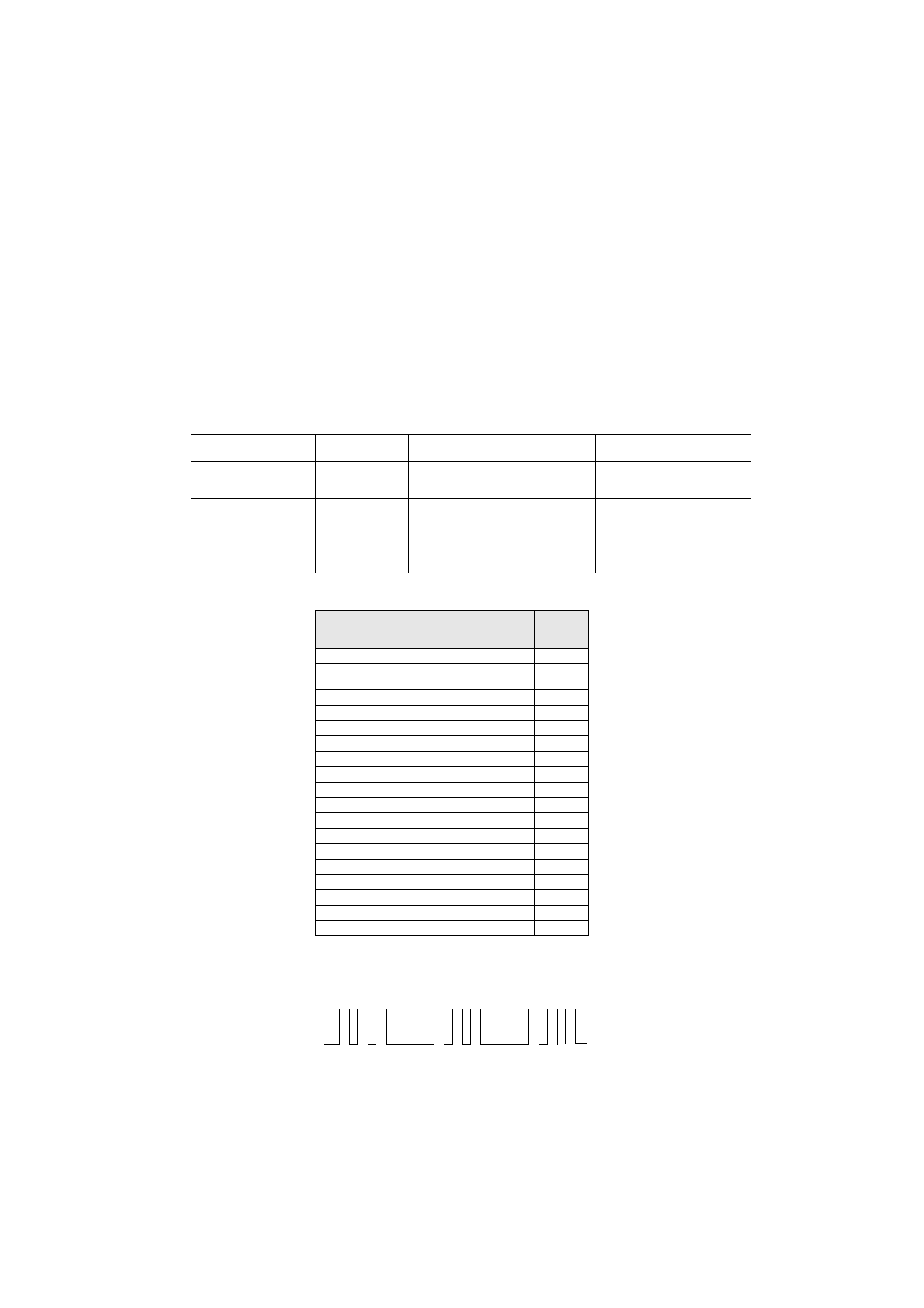
Flash Timing Example : e.g. error number 3
Diagnostic Item
Description
No of times Standby
LED Flashes
Probable cause
Location
Detected Symptoms
Power does not turn on
Does not light
Power cord is not plugged in
Fuse is burned out
Power does not come on
No power is supplied to the TV
AC power supply is faulty
+B Overcurrent (OCP)
2 times
H.OUT (Q6803/6804) is shorted. (D Board)
Linearity FET (Q6806) is shorted. (D Board)
IC6604 Power IC is shorted. (D Board)
Power does not come on
Load on power line has shorted
Vertical Deflection stopped
4 times
+15V is not supplied R6835 open (D Board)
-15V is not supplied R6834 open (D Board)
IC6700 is shorted (D Board)
Vertical deflection pulse has stopped
Power line has shorted
