
TRINITRON
® COLOR TELEVISION
SERVICE MANUAL
DA-4 CHASSIS
MODEL NAME
REMOTE COMMANDER
DESTINATION
CHASSIS NO.
9-965-986-01
KV-27HS420
RM-Y197
US
SCC-S76C-A
KV-27HS420
RM-Y197
CANADA
SCC-S70X-A
KV-29DRC430
RM-Y197
LATIN NORTH
SCC-S71S-A
KV-29DRC430
RM-Y197
LATIN SOUTH
SCC-S71T-A
KV-30HS420
RM-Y197
US
SCC-S76D-A
KV-30HS420
RM-Y197
CANADA
SCC-S70Y-A
KV-30HS420
RM-Y197
HAWAII
SCC-S69R-A
KV-32HS420
RM-Y197
US
SCC-S76E-A
KV-32HS420
RM-Y197
CANADA
SCC-S78A-A
KV-34HS420
RM-Y197
US
SCC-S76F-A
KV-34HS420
RM-Y197
CANADA
SCC-S78B-A
This manual is for units starting with the following S/N's:
For KV-27HS420/30HS420/32HS420/34HS420
For KV-29DRC430
4,000,001 to 4,499,999
8,000,001 to 8,499,999
9,000,001 to 9,499,999
4,500,001 to 7,999,999
8,500,001 to 8,999,999
9,500,001 to 9,999,999
HISTORY INFORMATION FOR THE FOLLOWING MANUAL:
ORIGINAL MANUAL ISSUE DATE: 7/2005
REVISION DATE
SUBJECT
7/2005
No revisions or updates are applicable at this time.
TRINITRON
® COLOR TELEVISION
SERVICE MANUAL
DA-4 CHASSIS
MODEL NAME
REMOTE COMMANDER
DESTINATION
CHASSIS NO.
9-965-986-01
KV-27HS420
RM-Y197
US
SCC-S76C-A
KV-27HS420
RM-Y197
CANADA
SCC-S70X-A
KV-29DRC430
RM-Y197
LATIN NORTH
SCC-S71S-A
KV-29DRC430
RM-Y197
LATIN SOUTH
SCC-S71T-A
KV-30HS420
RM-Y197
US
SCC-S76D-A
KV-30HS420
RM-Y197
CANADA
SCC-S70Y-A
KV-30HS420
RM-Y197
HAWAII
SCC-S69R-A
KV-32HS420
RM-Y197
US
SCC-S76E-A
KV-32HS420
RM-Y197
CANADA
SCC-S78A-A
KV-34HS420
RM-Y197
US
SCC-S76F-A
KV-34HS420
RM-Y197
CANADA
SCC-S78B-A
This manual is for units starting with the following S/N's:
For KV-27HS420/30HS420/32HS420/34HS420
For KV-29DRC430
4,000,001 to 4,499,999
8,000,001 to 8,499,999
9,000,001 to 9,499,999
4,500,001 to 7,999,999
8,500,001 to 8,999,999
9,500,001 to 9,999,999
Self Diagnosis
Supported model
KV-30HS420
RM-Y197

3
KV-27HS420/29DRC430/30HS420/32HS420/34HS420
KV-27HS420/29DRC430/30HS420/32HS420/34HS420
TABLE OF CONTENTS
SECTION TITLE
PAGE
SECTION TITLE
PAGE
Specifications ................................................................................. 4
Warnings and Cautions .................................................................. 6
Safety Check-Out ........................................................................... 7
Self-Diagnostic Function................................................................. 8
SECTION 1: DISASSEMBLY ................................................................11
1-1. Rear Cover Removal.............................................................11
1-2. Chassis Assembly Removal..................................................11
1-3. Service Position ....................................................................11
1-4. Picture Tube Removal.......................................................... 12
Anode Cap Removal Procedure .......................................... 12
Cable Wire Dressing ............................................................ 13
SECTION 2: SET-UP ADJUSTMENTS ................................................ 26
2-1. Beam Landing ...................................................................... 26
2-2. V-PIN and V-CEN Adjustment .............................................. 27
2-3. Convergence........................................................................ 27
2-3.1. Vertical and Horizontal Static Convergence ............ 27
2-3.2. Operation of BMC (Hexapole) Magnet .................... 27
2-3.3. TLH Plate Adjustment .............................................. 27
2-3.4. Screen-Corner Convergence................................... 28
2-3.5. Dynamic Convergence Adjustments........................ 28
2-4. Focus Adjustment................................................................. 29
2-4.1. Dynamic Focus/Dynamic Quadra-Pole Data ........... 29
2-5. Screen (G2).......................................................................... 30
2-6. Picture Quality Adjustments ................................................. 30
2-6.1. Video Input - Sub Contrast Adjustment.................... 30
2-6.2. Video Input - Sub Hue/Sub Color Adjustment.......... 31
2-6.3. RF Input - Sub Contrast Adjustment ........................ 31
2-6.4. RF Input - Sub Hue/Sub Color Adjustment .............. 32
2-7. White Balance (CRT) and Sub Bright Adjustment................ 32
2-7.1. Color Offset Adjustment Procedure ......................... 32
2-8. H Raster Center Adjustment ................................................ 33
2-9. Picture Distortion Adjustments ............................................. 33
2-9.1. NTSC (DRC) Full Mode Adjustment ........................ 33
CXA2170D-1................................................................... 33
CXA2170D-2................................................................... 34
2-9.2. 1080i HD Mode Adjustment ..................................... 34
2-9.3. Vertical Compressed Mode Check and Confirmation
(For 4x3 CRT Only) ................................................. 34
2-9.4
Normal, Zoom and Wide Zoom modes.................... 34
SECTION 3: SAFETY RELATED ADJUSTMENTS.............................. 35
3-1. Preparation Before Confirmation.......................................... 35
3-1.1
Hold-Down Operation Confirmation......................... 35
3-2. B+ Max Confirmation ........................................................... 35
3-3. B+ Voltage Check ................................................................ 35
3-4. High Voltage (HV) Check ..................................................... 35
3-5. Preparation for HV and Ik Protector Check.......................... 35
3-6. HV Protector Check ............................................................. 35
3-6-1. Cut Off Condition ..................................................... 35
3-6-2. High Light Condition ................................................ 36
3-7. IK Protector Check ............................................................... 36
3-8. Hold Down Check ................................................................ 36
3-9. Restoration........................................................................... 36
3-10.HV Service Flowchart........................................................... 37
HV Service Flowchart Table ................................................. 38
SECTION 4: CIRCUIT ADJUSTMENTS............................................... 39
4-1. Setting Service Adjustment Mode ........................................ 39
4-1.1. Service Adjustment Mode In .................................... 39
4-1.2. Service Adjustment Mode Memory .......................... 39
4-1.3. Reading the Memory ............................................... 39
4-1.4. Adjusting the Picture................................................ 39
4-1.5. Resetting the Data ................................................... 39
4-1.6. Resetting the MID NVM Data .................................. 39
4-1.7. Resetting the System NVM Data ............................. 39
4-1.8. Copy Function.......................................................... 39
4-2. Memory Write Confirmation Method .................................... 40
4-3. Remote Adjustment Buttons and Indicators ......................... 40
4-4. Service Data......................................................................... 41
KV-27HS420/29DRC430 Only ............................................. 41
KV-30HS420 Only ................................................................ 55
KV-32HS420 Only ................................................................ 69
KV-34HS420 Only ................................................................ 83
4-5. ID Map Table ........................................................................ 96
SECTION 5: DIAGRAMS ..................................................................... 97
5-1. Circuit Boards Location ........................................................ 97
5-2. Printed Wiring Boards and
Schematic Diagrams Information ......................................... 97
5-3. Block Diagrams .................................................................... 98
5-4. Schematics and Supporting Information ............................ 101
A Board Schematic Diagram (1 of 2).................................. 101
A Board Schematic Diagram (2 of 2).................................. 102
B Board Schematic Diagram (1 of 2) ................................. 105
B Board Schematic Diagram (2 of 2) ................................. 106
CH Board Schematic Diagram ........................................... 109
D Board Schematic Diagram (1 of 2) .................................. 111
D Board Schematic Diagram (2 of 2) ..................................112
HAX Board Schematic Diagram .........................................114
HB Board Schematic Diagram ............................................115
HCX Board Schematic Diagram..........................................116
M Board Schematic Diagram (1 of 4)..................................118
M Board Schematic Diagram (2 of 4)..................................119
M Board Schematic Diagram (3 of 4)................................. 120
M Board Schematic Diagram (4 of 4)................................. 121
P Board Schematic Diagram ............................................. 124
PA Board Schematic Diagram ........................................... 125
UY Board Schematic Diagram ........................................... 126
WY Board Schematic Diagram .......................................... 128
5-5. Semiconductors (1 of 2) ..................................................... 130
Semiconductors (2 of 2) ..................................................... 131
SECTION 6: EXPLODED VIEWS ...................................................... 132
6-1. Chassis (KV-27HS420/29DRC430 Only) ........................... 132
6-2. Picture Tube (KV-27HS420/29DRC430 Only).................... 133
6-3. Chassis (KV-30HS420/34HS420 Only).............................. 134
6-4. Picture Tube (KV-30HS420/34HS420 Only) ...................... 135
6-5. Chassis (KV-32HS420 Only).............................................. 136
6-6. Picture Tube (KV-32HS420 Only) ...................................... 137
SECTION 7: ELECTRICAL PARTS LIST .......................................... 138
4
KV-27HS420/29DRC430/30HS420/32HS420/34HS420
KV-27HS420/29DRC430/30HS420/32HS420/34HS420
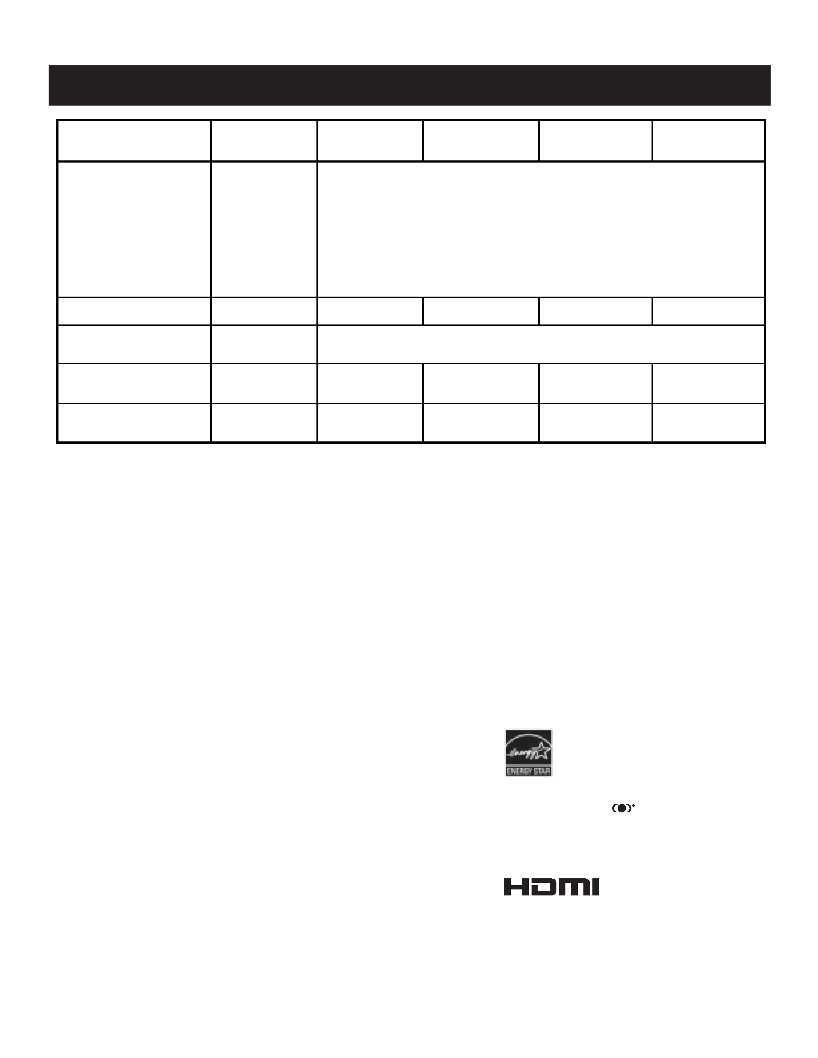
SPECIFICATIONS
Design and specifications are subject to change without notice.
1)
1 Vp-p 75 ohms unbalanced, sync negative
2)
Y: 1 Vp-p 75 ohms unbalanced, sync negative
C: 0.286 Vp-p (Burst signal), 75 ohms
3)
Y: 1.0 Vp-p, 75 ohms unbalanced, sync negative;
P
B
: 0.7 Vp-p, 75 ohms
P
R
: 0.7 Vp-p, 75 ohms
4)
500 mVrms (100% modulation), Impedance: 47 kilohms
5)
More than 408 mVrms at the maximum volume setting (variable)
More than 408 mVrms (fix); Impedance (output): 2 kilohms
KV-29DRC430
KV-27HS420
KV-30HS420
KV-32HS420
Power Requirements
220V, 50-60Hz
Number of Inputs/Outputs
Video
1)
4
S Video
2)
3
Y,PB, PR
3)
2
Audio
4)
7
Audio Out
5)
1
Monitor Out
1
Control-S (In/Out)
YES
Memory Stick
NO
Speaker Output (W)
10w x 2
15W Subwoofer
10W x 2
15W Subwoofer
10W x 2
15W Subwoofer
10W x 2
15W Subwoofer
Power Consumption (W)
In Use (Max)
240W
In Standby
1W
Dimensions (W x H x D)
mm 784 x 601.5 x 520 mm 784 x 601.5 x 520 mm
898 x 604 x 564.5 mm
898 x 698 x 598 mm
in 30
7/8 x 23 5/8 x 20 1/2 in 30 7/8 x 23 5/8 x 20 1/2 in 35 3/8 x 23 3/4 x 22 1/4 in
35
3/8 x 27 1/2 x 23 1/2 in
Mass
kg
50.2 kg
50.2 kg
68 kg
74.8 kg
lbs
111 lbs
111 lbs
150 lbs
165 lbs
194 lbs
88 kg
994 x 654 x 604 mm
39
1/8 x 25 3/4 x 23 3/4 in
1
1
YES
NO
240W
1W
10W x 2
15W Subwoofer
4
3
2
7
KV-34HS420
120V, 60Hz
As an ENERGY STAR Partner, Sony has determined
that this product or product models meets the
ENERGY STAR guidelines for energy efficiency.
ENERGY STAR is a U.S. registered mark.
Trademark Information
WOW, TruSurround and the
symbol are trademarks of SRS
Labs, Inc. WOW and TruSurround technology are incorporated
under license from SRS Labs, Inc.
Manufactured under license from BBE Sound, Inc. Licensed by BBE
Sound, Inc. under USP4638258, 5510752 and 5736897. BBE and BBE
symbol are registered trademarks of BBE Sound, Inc.
This TV incorporates High-Definition
Multimedia Interface (HDMITM)
technology. HDMI, the HDMI logo and
High-Definition Multimedia Interface are trademarks or registered
trademarks of HDMI Licensing LLC.
Wega, FD Trinitron, Steady Sound, Digital Reality Creation, Cap-
tion Vision, and CineMotion are registered trademarks of Sony
Corporation. ClearEdge VM and HD Detailer are trademarks of
Sony Corporation.

5
KV-27HS420/29DRC430/30HS420/32HS420/34HS420
KV-27HS420/29DRC430/30HS420/32HS420/34HS420
Television system
American TV standard, NTSC
Channel coverage
VHF: 2-13/ UHF: 14-69/ CATV: 1-125
Picture tube
FD Trinitron
®
tube
Visible screen size
27-inch picture measured diagonally (KV-27HS420/29DRC430 Only)
30-inch picture measured diagonally (KV-30HS420 Only)
32-inch picture measured diagonally (KV-32HS420 Only)
34-inch picture measured diagonally (KV-34HS420 Only)
Actual screen size
29-inch measured diagonally (KV-27HS420/29DRC430 Only)
32-inch measured diagonally (KV-30HS420 Only)
34-inch measured diagonally (KV-32HS420 Only)
36-inch measured diagonally (KV-34 HS420 Only)
Antenna
75 ohm external terminal for VHF/UHF
Supplied Accessories
Remote Commander RM-Y197
Two Size AA (R6) Batteries
Optional Accessories
AV Cable: VMC-810/820/830 HG
Audio Cable: RKC-515HG
Component Video Cable: VMC-10/30 HG
TV Stand: SU-27HX1 (KV-27HS420/29DRC430 Only)
TV Stand: SU-30HX1 (KV-30HS420 Only)
TV Stand: SU-32HX1 (KV-32HS420 Only)
TV Stand: SU-34HX1 (KV-34HS420 Only)