
- 1 -
SERVICE MANUAL
FE-2 CHASSIS
MODEL
COMMANDER
DEST
CHASSIS NO.
KV-29CL10B
RM-946
FR
SCC-Q54Q-A
KV-29CL10E
RM-946
ESP
SCC-Q53R-A
MODEL
COMMANDER
DEST
CHASSIS NO.
KV-29CL10K
RM-946
OIRT
SCC-Q51P-A
KV-29CL10U
RM-946
UK
SCC-Q52N-A
KV-29CL10
RM-946

- 2 -
TABLE OF CONTENTS
Section
Title
Page
Section
Title
Page
Specifications
....................
3
Connectors
....................
4
Self Diagnostic Software
....................
5
1. GENERAL
Switching on the TV and
Automatically Tuning
....................
6
Introducing and Using the
Menu System
....................
7
Menu Guide
....................
7
Teletext
....................
10
Fastext
....................
10
Connecting Optional Equipment ..................
11
Using Optional Equipment
....................
11
Specifications
....................
12
Troubleshooting
....................
12
2. DISASSEMBLY
2-1.
Rear Cover Removal
....................
13
2-2.
Chassis Removal and Refitting ....................
13
2-3.
A Board Removal [Step 1]
....................
14
2-4.
A Board Removal [Step 2]
....................
14
2-5.
Service Position
....................
14
2-6.
Picture Tube Removal
....................
15
Bottom Plates
....................
16
3. SET-UP ADJUSTMENTS
3-1.
Beam Landing
....................
17
3-2.
Convergence
....................
18
3-3.
Focus Adjustment
....................
20
3-4.
Screen (G2), White Balance
....................
20
4. CIRCUIT ADJUSTMENTS
4-1.
Electrical Adjustments
....................
21
4-2.
Test Mode 1
....................
23
4-3.
Test Mode 2
....................
23
5. DIAGRAMS
5-1.
Block Diagrams (1)
....................
24
Block Diagrams (2)
....................
25
5-2.
Circuit Board Location
....................
26
5-3.
Schematic Diagrams and
Printed Wiring Boards
....................
26
* A Board PWB
....................
28
* A Board Schematic
....................
29
* C Board PWB
....................
34
* C Board Schematic
....................
33
* DF Board PWB
....................
34
* DF Board Schematic ....................
35
5-4.
Semiconductors
....................
36
5-5.
IC Blocks
....................
38
6. EXPLODED VIEWS
6-1.
Chassis
....................
39
6-2.
Picture Tube
....................
40
7. ELECTRICAL PARTS LIST
....................
41
CAUTION
SHORT CIRCUIT THE ANODE OF THE PICTURE TUBE AND THE
ANODE CAP TO THE METAL CHASSIS, CRT SHIELD, OR THE
CARBON PAINTED ON THE CRT, AFTER REMOVAL OF THE
ANODE CAP.
WARNING !!
AN ISOLATION TRANSFORMER SHOULD BE USED DURING
ANY SERVICE WORK TO AVOID POSSIBLE SHOCK HAZARD
DUE TO LIVE CHASSIS, THE CHASSIS OF THIS RECEIVER IS
DIRECTLY CONNECTED TO THE POWER LINE.
SAFETY-RELATED COMPONENT WARNING !!
COMPONENTS IDENTIFIED BY SHADING AND MARKED
ON
THE SCHEMATIC DIAGRAMS, EXPLODED VIEWS AND IN THE
PARTS LIST ARE CRITICAL FOR SAFE OPERATION. REPLACE
THESE COMPONENTS WITH SONY PARTS WHOSE PART
NUMBERS APPEAR AS SHOWN IN THIS MANUAL OR IN
SUPPLEMENTS PUBLISHED BY SONY.
ATTENTION
APRES AVOIR DECONNECTE LE CAP DE'LANODE,
COURT-CIRCUITER L'ANODE DU TUBE CATHODIQUE ET
CELUI DE L'ANODE DU CAP AU CHASSIS METALLIQUE DE
L'APPAREIL, OU AU COUCHE DE CARBONE PEINTE SUR LE
TUBE CATHODIQUE OU AU BLINDAGE DU TUBE
CATHODIQUE.
ATTENTION !!
AFIN D'EVITER TOUT RISQUE D'ELECTROCUTION
PROVENANT D'UN CHÁSSIS SOUS TENTION, UN
TRANSFORMATEUR D'ISOLEMENT DOIT ETRE UTILISÈ LORS
DE TOUT DÈPANNAGE LE CHÁSSIS DE CE RÈCEPTEUR EST
DIRECTMENT RACCORDÈ Á L'ALIMENTATION SECTEUR.
ATTENTION AUX COMPOSANTS RELATIFS Á
LA SECURITÈ!!
LES COMPOSANTS IDENTIFIÈS PAR UNE TRAME ET PAR UNE
MARQUE
SUR LES SCHÈMAS DE PRINCIPE, LES VUES
EXPLOSÈES ET LES LISTES DE PIECES SONT D'UNE IMPOR-
TANCE CRITIQUE POUR LA SÈCURITÈ DU FONCTIONNEMENT,
NE LES REMPLACER QUE PAR DES COMPSANTS SONY DONT
LE NUMÈRO DE PIÈCE EST INDIQUÈ DANS LE PRÈSENT
MANUEL OU DANS DES SUPPLÈMENTS PUBLIÈS PAR SONY.
- 3 -
L
E
D
O
M
M
E
T
I
m
e
t
s
y
S
n
o
i
s
i
v
e
l
e
T
m
e
t
s
y
S
o
e
r
e
t
S
e
g
a
r
e
v
o
C
l
e
n
n
a
h
C
m
e
t
s
y
S
r
o
l
o
C
BL
,
I
,
K
/
D
,
H
/
G
/
B
M
A
C
I
N
/
N
A
M
R
E
G
o
e
r
e
t
S
,
0
1
F
-
2
0
F
,
2
1
E
-
2
0
E
:
F
H
V
9
6
B
-
1
2
B
,
9
6
F
-
1
2
F
,
9
6
E
-
1
2
E
:
F
H
U
Q
-
B
,
0
2
S
-
1
S
,
3
0
S
-
1
0
S
:
V
T
E
L
B
A
C
1
4
S
-
1
2
S
:
R
E
P
Y
H
M
A
C
E
S
,
L
A
P
8
5
.
3
C
S
T
N
,
3
4
.
4
C
S
T
N
)
N
I
O
E
D
I
V
(
EH
/
G
/
B
M
A
C
I
N
/
N
A
M
R
E
G
o
e
r
e
t
S
2
1
E
-
2
0
E
:
F
H
V
9
6
E
-
1
2
E
:
F
H
U
0
2
S
-
1
S
,
3
0
S
-
1
0
S
:
V
T
E
L
B
A
C
1
4
S
-
1
2
S
:
R
E
P
Y
H
M
A
C
E
S
,
L
A
P
8
5
.
3
C
S
T
N
,
3
4
.
4
C
S
T
N
)
N
I
O
E
D
I
V
(
KK
/
D
,
H
/
G
/
B
M
A
C
I
N
/
N
A
M
R
E
G
o
e
r
e
t
S
2
1
R
-
1
0
R
,
2
1
E
-
2
0
E
:
F
H
V
9
6
R
-
1
2
R
,
9
6
E
-
1
2
E
:
F
H
U
0
2
S
-
1
S
,
3
0
S
-
1
0
S
:
V
T
E
L
B
A
C
1
4
S
-
1
2
S
:
R
E
P
Y
H
M
A
C
E
S
,
L
A
P
8
5
.
3
C
S
T
N
,
3
4
.
4
C
S
T
N
)
N
I
O
E
D
I
V
(
UI
o
e
r
e
t
S
M
A
C
I
N9
6
B
-
1
2
B
:
F
H
U
M
A
C
E
S
,
L
A
P
8
5
.
3
C
S
T
N
,
3
4
.
4
C
S
T
N
)
N
I
O
E
D
I
V
(
e
b
u
T
e
r
u
t
c
i
P
n
o
r
t
i
n
i
r
T
D
F
y
a
l
p
s
i
D
t
a
l
F
)
s
e
h
c
n
i
9
2
(
m
c
2
7
x
o
r
p
p
A
d
e
r
u
s
a
e
m
e
r
u
t
c
i
p
m
c
8
6
x
o
r
p
p
A
(
.
)
y
ll
a
n
o
g
a
i
d
t
u
p
t
u
o
d
n
u
o
S
r
e
k
a
e
p
s
t
f
e
L
d
n
a
t
h
g
i
R)
S
M
R
(
W
5
x
2
)
r
e
w
o
P
c
i
s
u
M
(
W
0
1
x
2
]
R
A
E
R
[
s
l
a
n
i
m
r
e
T
t
u
p
t
u
O
/
t
u
p
n
I
s
n
o
i
t
a
c
i
f
i
c
e
p
S
l
a
r
e
n
e
G
r
o
t
c
e
n
n
o
c
o
r
u
E
n
i
p
-
1
2
:
1
)
d
r
a
d
n
a
t
s
C
E
L
E
N
E
C
(
.
s
l
a
n
g
i
s
o
e
d
i
V
d
n
a
o
i
d
u
A
r
o
f
s
t
u
p
n
I
.
B
G
R
r
o
f
s
t
u
p
n
I
o
i
d
u
A
d
n
a
o
e
d
i
V
V
T
f
o
s
t
u
p
t
u
O
.
s
l
a
n
g
i
s
s
t
n
e
m
e
r
i
u
q
e
R
r
e
w
o
PV
0
4
2
-
0
2
2
n
o
i
t
p
m
u
s
n
o
C
r
e
w
o
PW
4
9
r
o
t
c
e
n
n
o
c
o
r
u
E
n
i
p
-
1
2
:
2
.
s
l
a
n
g
i
s
o
e
d
i
V
d
n
a
o
i
d
u
A
r
o
f
s
t
u
p
n
I
.
o
e
d
i
V
-
S
r
o
f
s
t
u
p
n
I
o
i
d
u
A
d
n
a
o
e
d
i
V
V
T
f
o
s
t
u
p
t
u
O
.
e
c
a
f
r
e
t
n
i
k
n
il
t
r
a
m
S
.
)
e
l
b
a
t
c
e
l
e
S
(
.
s
l
a
n
g
i
s
s
n
o
i
s
n
e
m
i
Dm
m
3
2
5
x
8
9
5
x
8
8
7
x
o
r
p
p
A
t
h
g
i
e
Wx
o
r
p
p
Ag
k
8
.
5
4
s
e
i
r
o
s
s
e
c
c
A
d
e
il
p
p
u
S
)
1
(
r
e
d
n
a
m
m
o
C
e
t
o
m
e
R
6
4
9
-
M
R
)
2
(
y
r
e
t
t
a
b
6
R
d
e
t
a
n
g
i
s
e
d
C
E
I
s
e
r
u
t
a
e
F
r
e
h
t
O,
F
D
&
P
Q
D
,
n
o
i
t
c
u
d
e
R
e
s
i
o
N
o
t
u
A
.
k
n
il
t
r
a
m
S
,
t
x
e
t
e
l
e
T
]
T
N
O
R
F
[
s
l
a
n
i
m
r
e
T
t
u
p
t
u
O
/
t
u
p
n
I
l
o
r
t
n
o
C
d
e
r
a
r
f
n
I
:
m
e
t
s
y
S
l
o
r
t
n
o
C
e
t
o
m
e
R
k
c
a
j
e
n
o
h
p
d
a
e
Hk
c
a
j
i
n
i
m
o
e
r
e
t
s
s
t
n
e
m
e
r
i
u
q
e
r
r
e
w
o
P
c
d
V
3
n
o
i
t
a
n
g
i
s
e
d
C
E
I
s
e
i
r
e
t
t
a
b
2
)
A
A
e
z
i
s
(
6
R
s
t
u
p
n
i
o
i
d
u
As
k
c
a
j
o
n
o
h
p
s
t
u
p
n
i
o
e
d
i
Vk
c
a
j
o
n
o
h
p
.
e
c
i
t
o
n
t
u
o
h
t
i
w
e
g
n
a
h
c
o
t
t
c
e
j
b
u
s
e
r
a
s
n
o
i
t
a
c
i
f
i
c
e
p
s
d
n
a
n
g
i
s
e
D
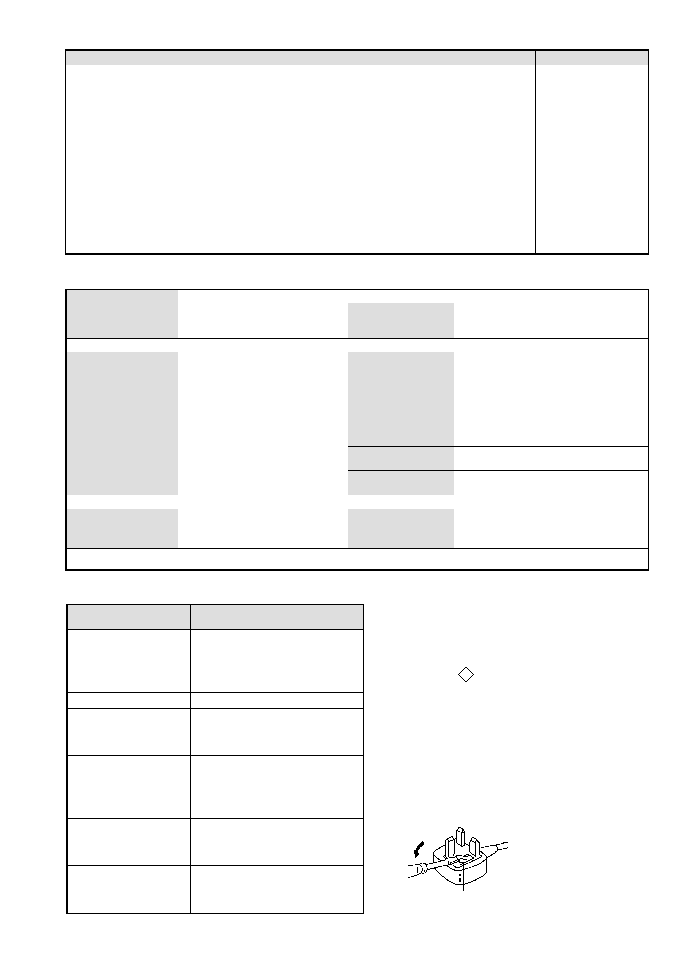
How to replace the fuse.
Open the fuse compartment with
a screwdriver blade and replace
the fuse.
FUSE
WARNING (UK Models only)
The flexible mains lead is supplied connected to a B.S. 1363 fused
plug having a fuse of 5 AMP rating. Should the fuse need to be
replaced, use a 5AMP FUSE approved by ASTA to BS 1362, ie
one that carries the ASA
T mark.
IF THE PLUG SUPPLIED WITH THIS APPLIANCE IS NOT SUIT-
ABLE FOR THE OUTLET SOCKETS IN YOUR HOME, IT SHOULD
BE CUT OFF AND AN APPROPRIATE PLUG FITTED. THE PLUG
SEVERED FROM THE MAINS LEAD MUST BE DESTROYED AS A
PLUG WITH BARED WIRES IS DANGEROUS IF ENGAGED IN A
LIVE SOCKET.
When an alternative type of plug is used, it should be fitted with a
5 AMP FUSE, otherwise the circuit should be protected by a 5AMP
FUSE at the distribution board.
e
m
a
N
l
e
d
o
M
m
e
t
I
B
0
1
L
C
9
2
-
V
K
E
0
1
L
C
9
2
-
V
K
K
0
1
L
C
9
2
-
V
K
U
0
1
L
C
9
2
-
V
K
P
A
PF
F
OF
F
OF
F
OF
F
O
P
I
PF
F
OF
F
OF
F
OF
F
O
y
t
i
r
o
i
r
P
B
G
RN
ON
ON
ON
O
x
o
B
r
e
f
o
o
WF
F
OF
F
OF
F
OF
F
O
1
t
r
a
c
SN
ON
ON
ON
O
2
t
r
a
c
SN
ON
ON
ON
O
)
3
(
n
i
t
n
o
r
FN
ON
ON
ON
O
4
t
r
a
c
SF
F
OF
F
OF
F
OF
F
O
r
o
t
c
e
j
o
r
PF
F
OF
F
OF
F
OF
F
O
G
/
B
m
r
o
NN
ON
ON
OF
F
O
I
m
r
o
NN
OF
F
OF
F
ON
O
K
/
D
m
r
o
NN
OF
F
ON
OF
F
O
S
U
A
m
r
o
NF
F
OF
F
OF
F
OF
F
O
L
m
r
o
NN
OF
F
OF
F
OF
F
O
T
A
S
m
r
o
NF
F
OF
F
OF
F
OF
F
O
M
m
r
o
NF
F
OF
F
OF
F
OF
F
O
t
x
e
t
e
l
e
TN
ON
ON
ON
O
o
e
r
e
t
S
m
a
c
i
NN
ON
ON
ON
O
- 4 -
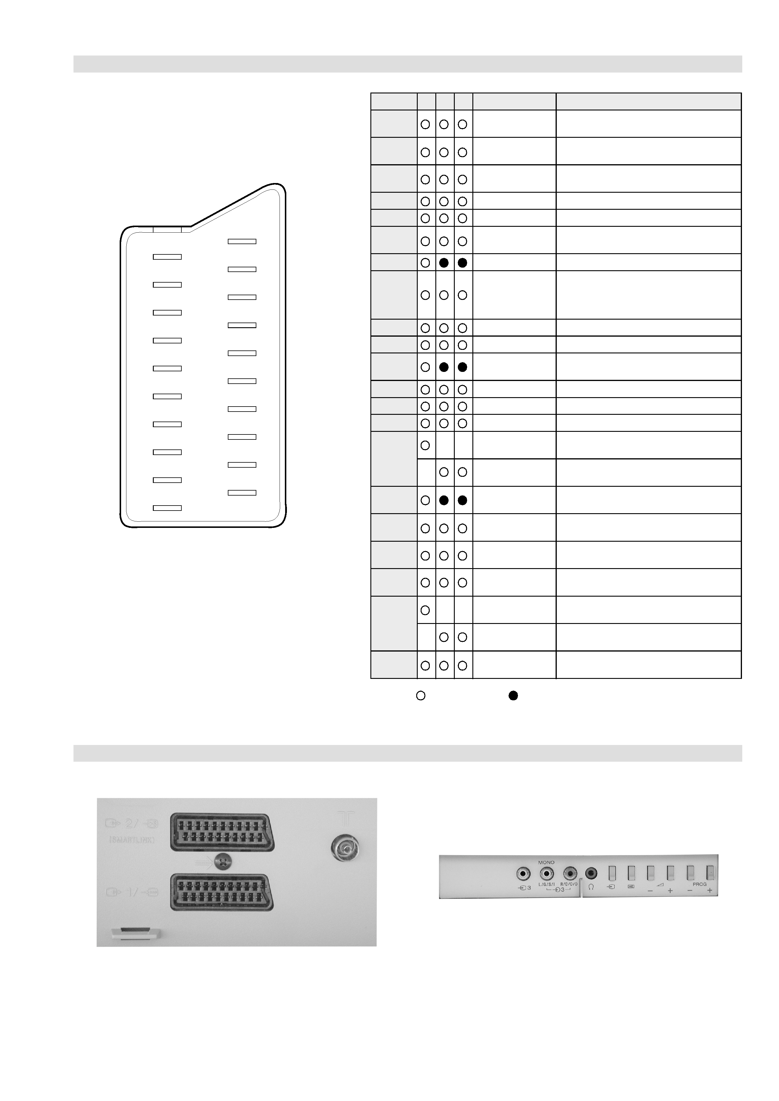
21 pin connector
Connected
Not Connected (open)
* at 20Hz - 20kHz
Pin No
1
2
4
Signal
Signal level
1
Audio output B
(right)
Standard level : 0.5V rms
Output impedence : Less than 1kohm*
2
Audio output B
(right)
Standard level : 0.5V rms
Output impedence : More than 10kohm*
3
Audio output A
(left)
Standard level : 0.5V rms
Output impedence : Less than 1kohm*
4
Ground (audio)
5
Ground (blue)
6
Audio input A
(left)
Standard level : 0.5V rms
Output impedence : More than 10kohm*
7
Blue input
0.7 +/- 3dB, 75 ohms positive
8
Function select
(AV control)
High state (9.5-12V) : Part mode
Low state (0-2V) : TV mode
Input impedence : More than 10K ohms
Input capacitance : Less than 2nF
9
Ground (green)
10
Open
11
Green
Green signal : 0.7 +/- 3dB, 75 ohms,
positive
12
Open
13
Ground (red)
14
Ground (blanking)
15
_
_
Red input
0.7 +/- 3dB, 75 ohms, positive
_
(S signal Chroma
input)
0.3 +/- 3dB, 75 ohms, positive
16
Blanking input
(Ys signal)
High state (1-3V) Low state (0-0.4V)
Input impedence : 75 ohms
17
Ground (video
output)
18
Ground (video
input)
19
Video output
1V +/- 3dB, 75ohms, positive sync 0.3V
(-3+10dB)
20
_
_
Video input
1V +/- 3dB, 75ohms, positive sync 0.3V
(-3+10dB)
_
Video input
Y (S signal)
1V +/- 3dB, 75ohms, positive sync 0.3V
(-3+10dB)
21
Common ground
(plug, shield)
19
17
15
13
11
9
7
5
3
1
20
18
16
14
12
10
8
6
4
2
21
Rear Connection Panel
Front Connection Panel
- 5 -
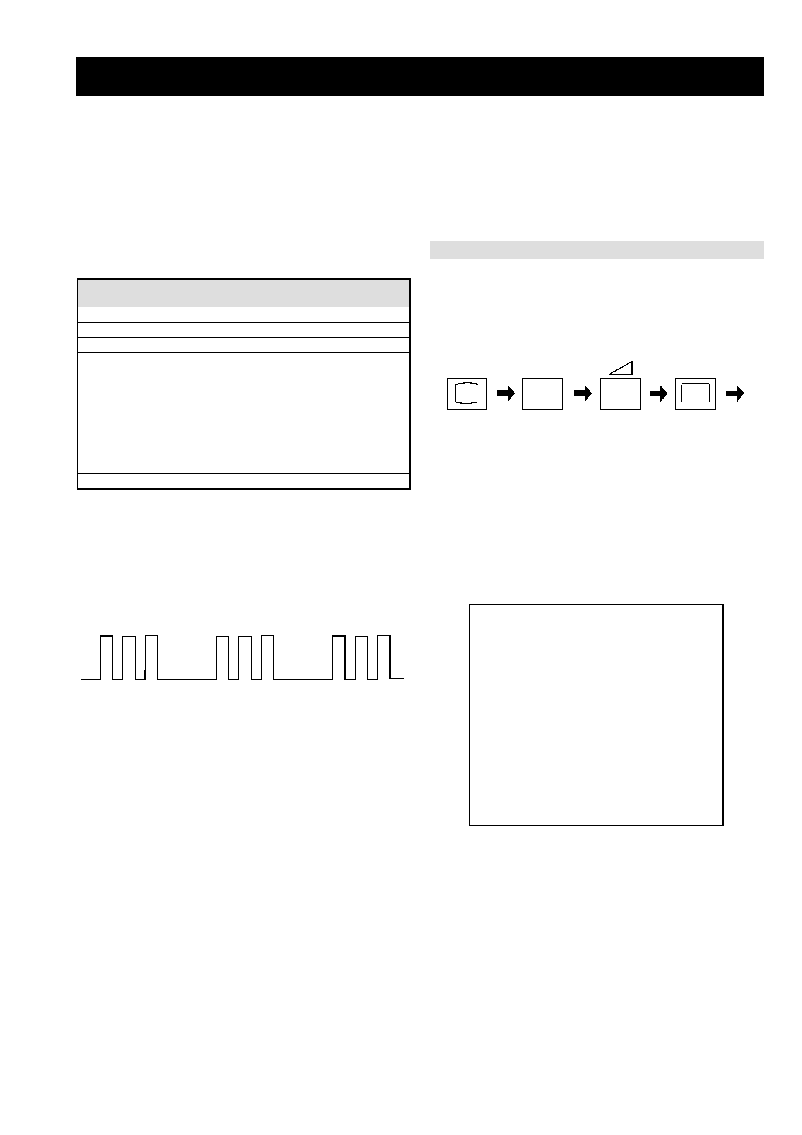
FE-2 SELF DIAGNOSTIC SOFTWARE
The identification of errors within the FE-2 chassis is triggered in one of two ways :- 1: Busy or 2: Device failure to respond to IIC. In the event
of one of these situations arising the software will first try to release the bus if busy (Failure to do so will report with a continuous flashing
LED) and then communicate with each device in turn to establish if a device is faulty. If a device is found to be faulty the relevant device number
will be displayed through the LED (Series of flashes which must be counted) See table 1., non fatal errors are reported using this method.
Each time the software detects an error it is stored within the NVM. See Table 2.
Flash Timing Example : e.g. error number 3
StBy LED
ON
ON
ON
OFF
OFF
Table 1
How to enter into Table 2
1.
Turn on the main power switch of the TV set and enter into
the `Stanby Mode'.
2.
Press the following sequence of buttons on the Remote
Commander.
i+
5
-
(ON SCREEN
(DIGIT 5)
(VOLUME -)
(TV)
DISPLAY)
3.
The following table will be displayed indicating the error
count.
Table 2
Note: To clear the error count data press `80' on the Remote
commander.
U
N
E
M
R
O
R
R
E
2
0
E
3
0
E
4
0
E
5
0
E
6
0
E
7
0
E
8
0
E
9
0
E
0
1
E
1
1
E
E
M
I
T
G
N
I
K
R
O
W
S
R
U
O
H
S
E
T
U
N
I
M
P
C
O
A
/
N
P
V
O
C
N
Y
S
V
R
K
I
C
I
I
M
V
N
E
L
G
N
U
J
R
E
N
U
T
P
D
N
U
O
S
V
8
)
5
5
2
,
0
(
)
5
5
2
,
0
(
)
5
5
2
,
0
(
)
5
5
2
,
0
(
)
5
5
2
,
0
(
)
5
5
2
,
0
(
)
5
5
2
,
0
(
)
5
5
2
,
0
(
)
5
5
2
,
0
(
)
5
5
2
,
0
(
0
0
0
0
0
0
0
0
0
0
2
1
1
e
g
a
s
s
e
M
r
o
r
r
E
D
E
L
e
d
o
C
r
o
r
r
e
o
N0
0
d
e
v
r
e
s
e
R1
0
)
n
o
i
t
c
e
t
o
r
P
t
n
e
r
r
u
C
r
e
v
O
(
P
C
O2
0
d
e
s
U
t
o
N3
0
c
n
y
S
l
a
c
i
t
r
e
V
o
N4
0
n
o
r
e
w
o
p
t
a
r
o
r
r
E
R
K
I5
0
n
o
r
e
w
o
p
t
a
w
o
l
s
e
n
il
a
t
a
d
r
o
/
d
n
a
k
c
o
l
c
s
u
b
C
I
I6
0
n
o
r
e
w
o
p
t
a
e
g
d
e
l
w
o
n
k
c
a
s
u
b
C
I
I
o
n
M
V
N7
0
d
e
s
U
t
o
N8
0
n
o
r
e
w
o
p
t
a
e
g
d
e
l
w
o
n
k
c
a
o
n
r
e
n
u
T9
0
r
o
r
r
E
r
o
s
s
e
c
o
r
P
d
n
u
o
S0
1
r
o
r
r
e
s
t
l
o
v
8
r
e
ll
o
r
t
n
o
c
e
l
g
n
u
J1
1