US Model
Chassis No.
Canadian Model
Chassis No.
E-A
ANU-2 CHASSIS
MODELS OF THE SAME SERIES
KV-27EXR95
Television
system
American
TV
standards
Channel coverage
VHF: 2
13
UHF: 14
69
Picture tube
Antenna
Input
output
Cable TV: 1
125
tube
picture measured
diagonally
picture tube measured
diagonally
external anlenna terminal
for VHF/UHF
VIDEO
and 2 IN
S VIDEO IN
mini
Y:
Vp-p,
unbalanced,
sync
negative
C: 0.286 Vp-p (Burst signal),
Video (phono jacks): 1 Vp-p,
unbalanced,
sync
negative
Audio (phono jacks): 500
(100%
modulation)
Impedance: 47 kilohms
VIDEO 2 OUT
Video (phono jack):
unbalanced,
sync negative
Audio (phono jacks):
Impedance:
10
kilohms
AUDIO
OUT
(VARIABLE)
(phono jacks)
More than 408
at the
maximum
volume
setting
(variable)
Impedance: 5 kilohms
KV-27EXR90
SPECIFICATIONS
Speaker output
Power requirements 120 V AC, 60 Hz
Power consumption Maximum: 165 W
Standby: 1.5 W
Dimensions (h/w/d) 595
683
573.5 mm
(23%
27
22% inch)
Supplied accessories
Remote Commander
(1) with
2 size AA (R6) EVEREADY batteries
Terminal cover (1)
Recommended accessories
U/V mixer EAC-66
Connecting
cable
SPEAKER SIZE
TWEETER
50mm
X2
WOOFER 85mm X2
(3
TOTAL 2 SPEAKER BOXES
INTERNAL AUDIO POWER
FRONT 5 WATTS X 2
CONDITION
8 ohms, 10%
AUDIO
FREQUENCY
RESPONSE
TWEETER 2kHz
WOOFER
-2kHz
CONDITION
BASS/TREBLE ARE IN NORMAL CONDITION
Design and specifications are subject to change without
notice.
TV
TABLE OF CONTENTS
Section
Title
1. GENERAL
l-l.
Location of Controls ......................
4
1-2.
Presetting TV Channels ....................
5
1-3.
TV Programs ......................
6
1-4.
Adjusting Picture and Sound Quality
.........
7
1-5.
Using Picture-in-Picture. .....................
9
1-6.
Using the Remote Commander
...............
11
1-7.
Using the guide Function .....................
13
1.8.
Enjoying Other Useful Features .............
19
1-9.
Troubleshooting
.........................
20
2. DISASSEMBLY
2-1.
Rear Cover Removal ..........................
21
2-2.
and U2 Boards Removal ...................
21
2-3.
Service Position ..........................
21
2-4.
Picture Tube Removal ......................
22
3. SET-UP ADJUSTMENTS
3-1.
Beam Landing ................................
23
3-2.
Convergence ................................
24
3-3.
Focus ....................................
26
3-4.
G2 (Screen) and White Balance Adjustments ....
26
WARNING
!!
ATTENTION!!
AN
ISOLATION
TRANSFORMER
SHOULD
BE
USED
DURING
ANY
SERVICE
TO
AVOID
POSSIBLE
SHOCK
HAZARD,
BECAUSE
OF
LIVE
CHASSIS.
THE
CHASSIS
OF
THIS
RECEIVER
IS
DIRECTLY
CON-
NECTED TO THE AC POWER LINE.
D'EVITER
TOUT
RISQUE
PROVENANT D'UN
TENSION,
UN
TRANSFORMATEUR
D'ISOLEMENT
ETRE
LORS DE TOUT
LE
DE CE
EST
ii
L'ALIMENTATION
SECTEUR.
SAFETY-RELATED COMPONENT WARNING !!
COMPONENTS IDENTIFIED BY SHADING AND MARK
!
ON
THE
SCHEMATIC
DIAGRAMS,
EXPLODED
VIEWS AND IN THE PARTS LIST ARE CRITICAL TO
SAFE
OPERATION.
REPLACE
THESE
COMPONENTS
WITH
SONY
PARTS
WHOSE
PART
NUMBERS
APPEAR
AS SHOWN IN THIS MANUAL OR IN SUPPLEMENTS
PUBLISHED
BY
SONY.
CIRCUIT
ADJUSTMENTS
THAT
ARE
CRITICAL
TO
SAFE
OPERATION
ARE
IDENTIFIED
IN
THIS
MANUAL.
FOLLOW THESE PRO-
CEDURES
WHENEVER
CRITICAL
COMPONENTS
ARE
REPLACED
OR
IMPROPER
OPERATION
IS
SUSPECTED.
Section
Title
4.
SAFETY RELATED ADJUSTMENTS . . . . . . . . . .
28
5. CIRCUIT ADJUSTMENTS
5-l.
Electrical Adjustment by Remote Commander . .
31
5-2.
A Board Adjustments . . . . . . . . . . . . . . . . . . . . . . .
33
5-3.
P Board Adjustments .
. . . . . . . . . . . . . . . .
37
6. DIAGRAMS
6-1.
.
.
. . . . . . . . . . . .
. . . .
39
6-2.
Circuit Boards Location
. . . . . . . . . . . . . . . . . . . .
43
6-3.
Printed Wiring Boards and
Schematic Diagrams
. . . . . . . . . . .
. . . . . . . .
43
6-4.
Semiconductors
. . . . . . . . . . . . . . . . . . . . . .
67
7. EXPLODED VIEWS
7-1.
Chassis . . . . . . . . . . . . . . . .
.
. . . . . . . . . . . .
69
7-2.
Picture Tube......... . .
. . . . . . . . . . . . . . . . . .
8. ELECTRICAL PARTS LIST . . . . . . . . . . .
. . . . 71
ATTENTION
AUX
COMPOSANTS
LA
LES COMPOSANTS IDENTIFIES PAR UNE TRAME ET
PAR UNE MARQUE
LES
DE PRINCIPE,
LES
VUES
ET
LES
DE
PIECES
SONT
D'UNE
IMPORTANCE
CRITIQUE
POUR
LA
DU FONCTIONNEMENT. NE LES
PLACER
QUE
PAR
DES
COMPOSANTS
SONY
DONT
LE
DE
EST
DANS LE
MANUEL
OU
DANS
DES
SUPPLEMENTS
PAR
SONY. LES
DE CIRCUIT DONT
TANCE
EST
CRITIQUE
POUR
LA
DU
FONCTIONNEMENT
SONT
IDENTIFIES
DANS
LE
MANUEL.
CES
LORS
DE
CHAQUE
REMPLACEMENT
DE
COMPOSANTS
CRITIQUES,
OU
LORSQU'UN
MENT EST
SAFETY
CHECK-OUT
(US Model only)
After correcting the original service problem,
perform the following safety checks before releasing
the set to the customer:
1.
Check the area of your repair for unsoldered or
poorly-soldered connections. Check the entire
board surface for solder splashes and bridges.
2.
Check the interboard wiring to ensure that no
wires are "pinched" or contact high-wattage
resistors,
3. Check that all control knobs, shields, covers,
ground straps, and mounting hardware have
been replaced. Be absolutely certain that you
have
replaced all the insulators.
4.
Look for unauthorized replacement parts, par-
ticularly transistors, that were installed during a
previous repair. Point them out to the customer
and recommend their replacement.
5.
Look for parts which, though functioning, show
obvious signs of deterioration. Point them out
to the customer and recommend their replace-
ment.
6.
Check the line cord for cracks and abrasion.
Recommend the replacement of any such line
cord to the customer.
7.
Check the condition of the
antenna
(if any).
Make sure the end is not broken off, and has
the plastic cap on it. Point out the danger of
impalement on a broken antenna to the
customer,
and
recommend
the
antenna's
replacement.
8.
Check the B+ and HV to see they are at the
values specified. Make sure your instruments
are accurate; be suspicious of your HV meter
if sets always have low HV.
9.
Check the antenna terminals, metal trim,
"metallized"
knobs, screws, and all other
exposed metal parts for AC leakage.
Check
leakage as described below.
LEAKAGE
TEST
The AC leakage from any exposed metal part to
earth ground and from all exposed metal parts to any
exposed metal part having a return to chassis, must
not
exceed 0.5
(500
Leakage
current can be measured by any one of three
methods.
1.
A commercial leakage tester, such as the
Simpson 229 or RCA WT-540A. Follow the
manufacturers' instructions to use these instru-
ments.
2.
A battery-operated AC milliammeter. The Data
Precision 245 digital multimeter is suitable for
this job.
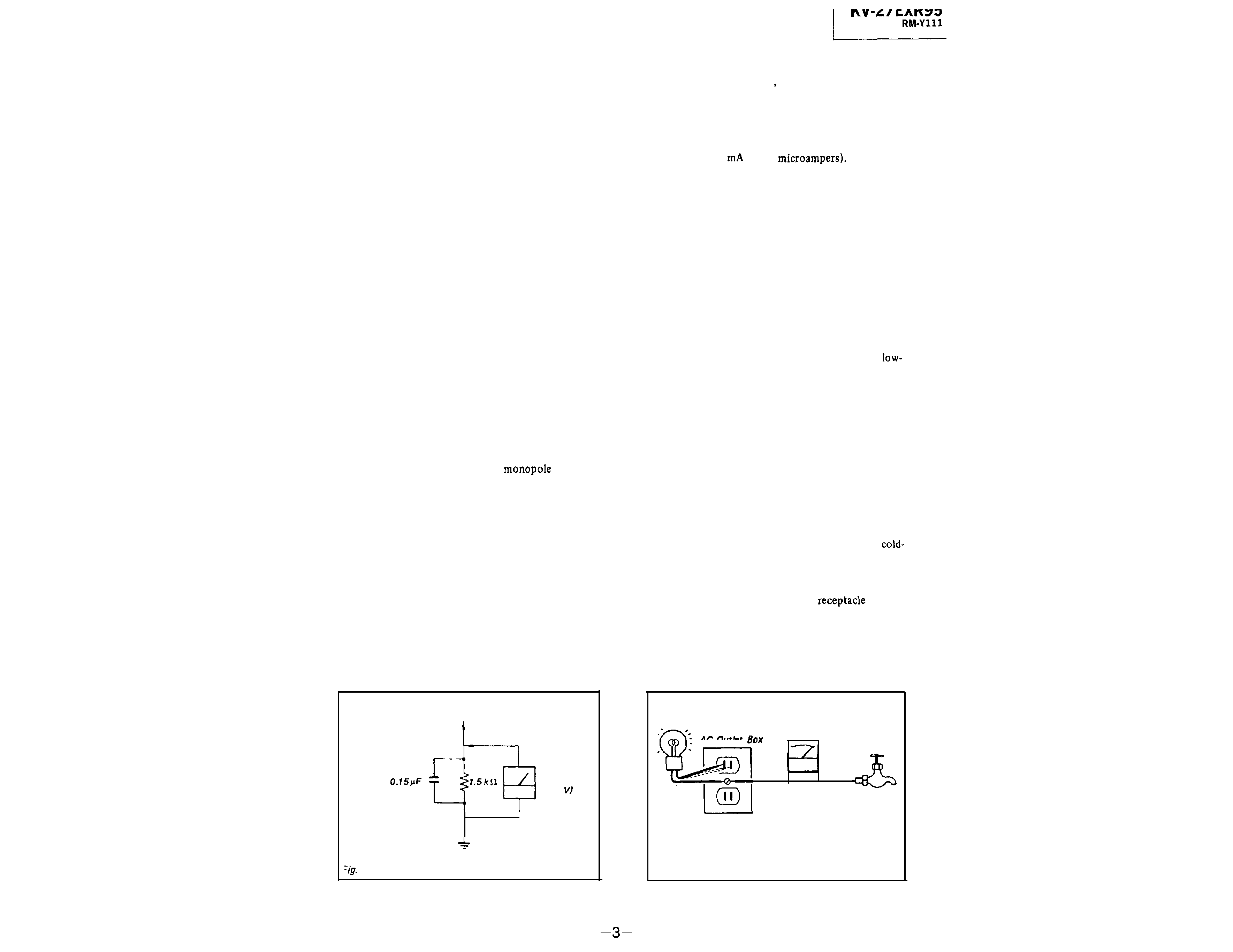
3.
Measuring the voltage drop across a resistor by
means of a VOM or battery-operated AC volt-
meter.
The "limit" indication is 0.75 V, so
analog meters must have an accurate
voltage scale.
The Simpson 250 and Sanwa
SH-63Trd are examples of a passive VOM that
is suitable. Nearly all battery operated digital
multimeters that have a 2V AC range are
suitable. (See Fig. A)
HOW TO FIND A GOOD EARTH GROUND
A cold-water pipe is guaranteed earth ground; the
cover-plate retaining screw on most AC outlet boxes is
also at earth ground. If the retaining screw is to be
used as your earth-ground, verify that it is at ground
by measuring the resistance between it and a
water pipe with an ohmmeter. The reading should be
zero ohms.
If a cold-water pipe is not accessible,
connect a 60-100 watts trouble light (not a neon
lamp) between the hot side of the
and the
retaining screw. Try both slots, if necessary, to locate
the hot side of the line, the lamp should light at
normal brilliance if the screw is at ground potential.
(See Fig. B)
To Exposed Metal
Parts on Set
AC
voltmeter
(0.75
Trouble
Light
Ohmmeter
AC Outlet
Cold-water Pipe
Earth Ground
A.
Using an AC voltmeter to check AC leakage.
Fig. B.
Checking for earth ground.
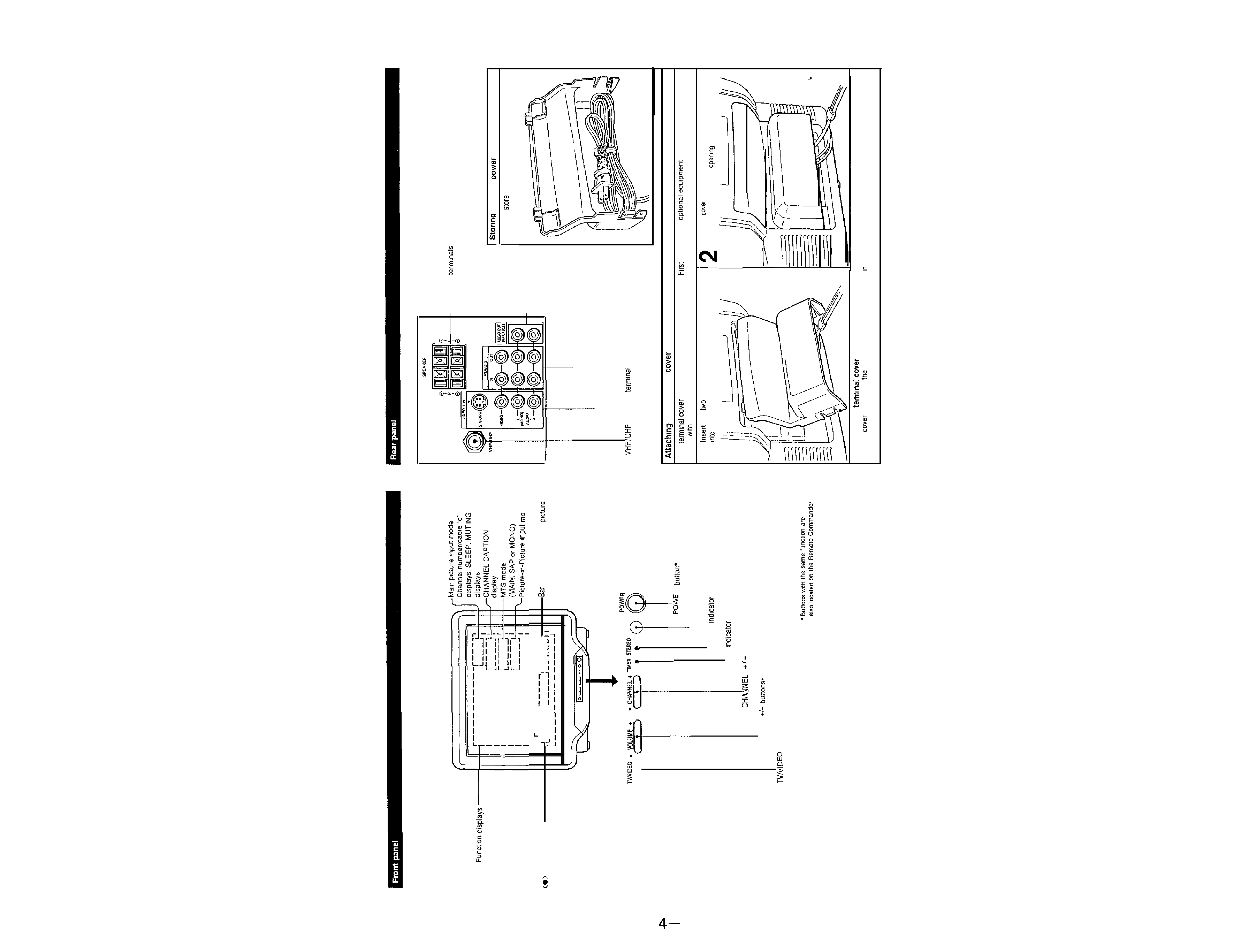
SECTION
1
GENERAL
l-l.
LOCATION OF CONTROLS
GUIDE
Picture-Sound level
adjustment displays
Picture-m-Picture
mode
SRS display
CURRENT TIME displays
I
____
-------
____
,
-----
I
____
display for volume.
or sound adjustment
POWER
Remote control detector
STEREO
tamp
TIMER
lamp
buttons'
VOLUME
button*
SPEAKER
the AC
cord
You can
the AC power cord at the rear of
the termmal cover, as illustrated here.
1
AUDIO
OUT
(VARIABLE)
tacks
VIDEO 2 IN and OUT jacks
VIDEO 1 IN jacks (S VIDEO,
VIDEO/AUDIO)
antenna
the termmal
The
comes packed separately from the TV.
connect any
you want
to use
your TV, then attach the cover as shown below.
1
the
tabs at the top of the termmal cover
Push the
onto the rear panel so that the connected
the rear panel as shown below.
cords extend out from the
at the bottom.
To remove the
Pull the
away from
rear panel to the angle shown
step 1. then pull down to release the cover
from the rear panel.
number buttons
DISPLAY button
CABLE BOX button
JUMP button
ENTER button
VOL (volume)
buttons*
CH (channel)
buttons'
VTR
CODE SET button
(Pre-Programmed function)
A/V WINDOW (audio and
adjusting) buttons
Channel presetting buttons
PIP
buttons
Video operating buttons
MTS (multichannel TV sound) button
CABLE button
Installing
Remove the battery
cover.
I
Battery life
normal
will
up to hall a year.
If the Remote Commander does not operate properly, the
be exhausted. Replace both with new ones.
To
damage from possible battery leakage
Remove the
when the Remote Commander will
not be used for a long time.
2 Insert two AA
correct polarity.
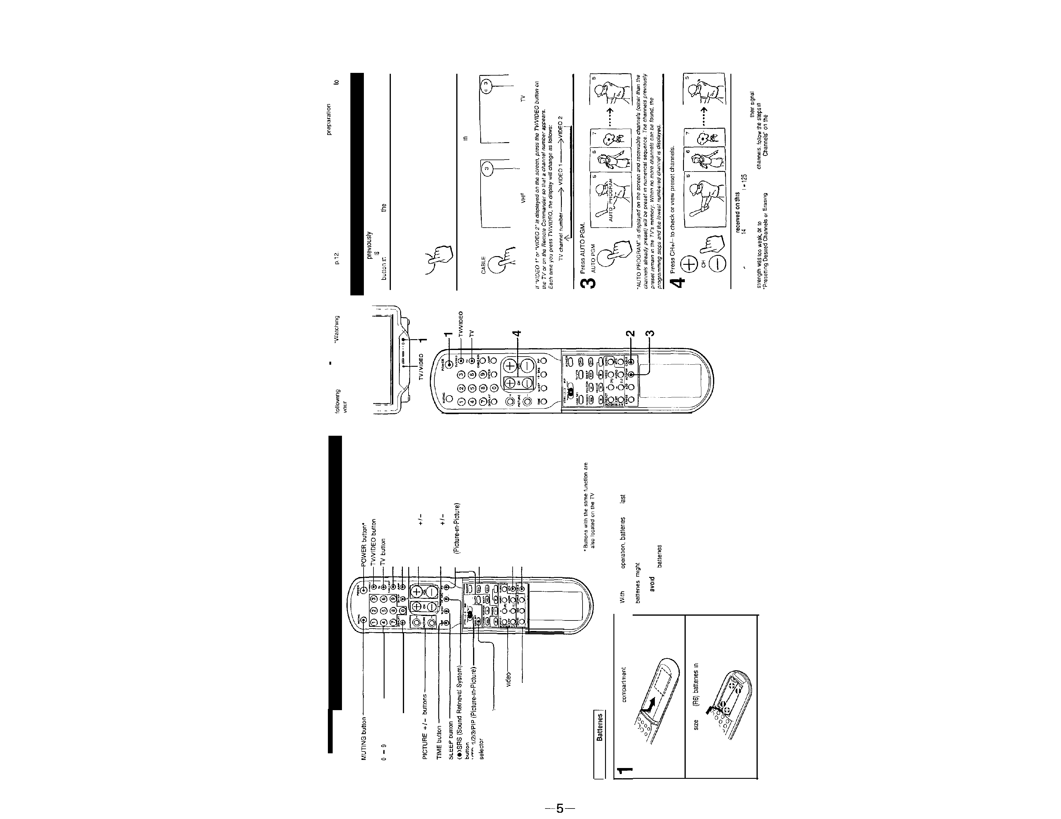
1-2. PRESETTING TV CHANNELS
VHF channels (2
13) have been preset on your TV. You can watch those TV channels without further
by
the steps under
TV Programs" on
For UHF and cable channels. you must first preset channels
TV
If you have
pressed the CABLE BOX button, the Remote
Commander
set to control the cable converter box. not the TV. Press the
TV
order to control
TV with the Remote Commander.
1
Press POWER on the TV or the Remote Commander to turn the TV on
POWER
n
2
Press CABLE so that a channel number appears
the mode that
you want to preset. TV or cable.
To preset
or UHF channels
To preset cable
channels
Channels that can be
TV:
VHF. 2
13
UHF
-69
Cable:
To add channels that could not be preset automatically because
erase unnecessary
unnecessary
next page.