SERVICE MANUAL
CHASSIS
BC-5
MODEL
COMMANDER
DEST. CHASSIS NO.
MODEL
COMMANDER
DEST. CHASSIS NO.
KV-14FV1B
RM-C816
FR
SCC-xxxx-A
KV-14FV1D RM-C814
AEP
SCC-xxxx-A
KV-14FV1E
RM-C814
ESP
SCC-Q62B-A
KV-14FV1U RM-C815
UK
SCC-xxxx-A
KV-21FV1B
RM-C816
FR
SCC-xxxx-A
KV-21FV1D
RM-C814
AEP
SCC-xxxx-A
KV-21FV1E
RM-C814
ESP
SCC-Q62A-A
KV-21FV1U
RM-C815
UK
SCC-xxxx-A
14
Please file according to model size. ....
FD TRINITRON® COLOUR VIDEO TV
2
SPECIFICATIONS
General
Rear Terminals
:1/
21-pin scart connector (CENELEC standard)
including audio/video input, RGB input, TV
audio/video output.
Front Terminals
...2 video input phono jack
2 audio input phono jack
headphones jack
Clock
Quartz locked
Clock back up
Approx. 7 days
Power requirements
220-240 V AC, 50Hz
Sound Output:
1 x 6W (music power)
1 x 3W (RMS Mono)
Power Consumption:
· KV-14FV1U: 86 W
· KV-21FV1U: 107 W
Standby Power Consumption:
< 2 W
Dimensions:
· KV-14FV1U: Approx. 375 x 398 x 407 mm.
· KV-21FV1U: Approx. 489 x 500 x 477 mm.
Weight:
· KV-14FV1U: Approx. 15.6 Kg.
· KV-21FV1U: Approx. 27.2 Kg.
Accessories supplied:
1 Remote Control (RM-C815)
2 Batteries (IEC designated)
Other features:
Teletext, Fastext, TOPtext
Sleep Timer
Wake UP Timer
Parental Lock
Auto Head Cleaner
Dial Timer
VideoPlus+
TV Section
TV system:
I
Colour system:
PAL, SECAM
NTSC 3.58, 4.43 (only Video In)
Channel Coverage:
UHF: B-21, B69
Picture Tube:
· KV-14FV1U:
Flat Display Trinitron.
14" (approx. 37 cm. measured diagonally)
· KV-21FV1U:
Flat Display Trinitron.
21" (approx. 55 cm. measured diagonally)
VCR Section
Format:
VHS Standard
Video recording system:
Rotary 2-head helical scanning system
Audio recording system:
Monaural
Video signal:
This Video TV is designated to receive TV
programmes based on PAL (I) colour system and to
record and play on PAL system. The Video TV can
also play tapes on NTSC colour system.
Tape speed:
PAL:
SP: 23.39 mm/sec.
LP: 11.70 mm/sec.
NTSC (playback only):
SP: 33.35 mm/sec.
LP: 11.12 mm/sec.
Maximum recording time:
SP: 4 hours with E-240 tape
LP: 8 hours with E-240 tape
Design and specifications are subject to change without notice.

3
TABLE OF CONTENTS
Section
Title
Page
Section
Title
Page
SELF DIAGNOSIS FUNCTION ......................................
4
[ TV SECTION]
1. GENERAL .........................................................
7
2. DISASSEMBLY
2-1.
Rear Cover Removal ............................................... 16
2-2.
Chassis Assy Removal ............................................ 16
2-3.
Service Position (A Board) ..................................... 16
2-4.
A Board Removal .................................................... 16
2-5.
Harnes Location ...................................................... 17
2-6.
Picture Tube Removal ............................................. 18
3. SET-UP ADJUSTMENTS
3-1.
Beam Landing ......................................................... 19
3-2.
Convergence ............................................................ 20
3-3.
Focus Adjustment .................................................... 21
3-4.
Screen (G2) Adjustment .......................................... 21
3-5.
White Barance Adjustment ..................................... 22
3-6.
Picture Distortion Adjustment ................................. 22
CAUTION
SHORT CIRCUIT THE ANODE OF THE PICTURE TUBE AND
THE ANODE CAP TO THE METAL CHASSIS, CRT SHIELD, OR
CARBON PAINTED ON THE CRT, AFTER REMOVING THE
ANODE.
SAFETY-RELATED COMPONENT WARNING!!
COMPONENTS IDENTIFIED BY SHADING AND MARK
! ON
THE SCHEMATIC DIAGRAMS, EXPLODED VIEWS AND IN THE
PARTS LIST ARE CRITICAL FOR SAFE OPERATION. REPLACE
THESE COMPONENTS WITH SONY PARTS WHOSE PART
NUMBERS APPEAR AS SHOWN IN THIS MANUAL OR IN
SUPPLEMENTS
PUBLISHED
BY
SONY.
CIRCUIT
ADJUSTMENTS THAT ARE CRITICAL FOR SAFE OPERATION
ARE IDENTIFIED IN THIS MANUAL. FOLLOW THESE
PROCEDURES WHENEVER CRITICAL COMPONENTS ARE
REPLACED OR IMPROPER OPERATION IS SUSPECTED.
4. CIRCUIT ADJUSTMENTS
4-1.
Adjustments with Commander ................................ 23
4-2.
Adjustment Method ................................................. 24
4-3.
Service Data ............................................................ 25
4-4.
A Board Adjustment ................................................ 26
5. DIAGRAMS
5-1.
Block Diagrams ....................................................... 27
5-2.
Circuit Boards Location .......................................... 33
5-3.
Printed Wiring Boards and Schematic Diagrams .... 33
·
A Board .................................................................... 34
·
CVM Board .............................................................. 41
6. EXPLODED VIEWS
6-1.
Picture Tube ............................................................ 77
6-2.
Chassis ..................................................................... 78
7. ELECTRICAL PARTS LIST ...................................... 82
[ VIDEO SECTION]
1. GENERAL ....................................................................... 46
2. DISASSEMBLY ............................................................. 47
3. CIRCUIT ADJUSTMENTS ........................................ 48
4. INTERFACE, IC PIN FUNCTION
DESCRIPTION .............................................................. 51
5. DIAGRAMS ..................................................................... 55
6. EXPLODED VIEWS ..................................................... 79
7. ELECTRICAL PARTS LIST ...................................... 90
ATTENTION
APRES
AVIOR
DECONNECTE
LE
CAP
DE
L'ANODE,
COURTCIRCUITER L'ANODE DU TUBE CATHODIQUE ET CELUI
DE L'ANODE DU CAP AU CHASSIS METALLIQUE DE
L'APPAREIL, OU AU COUCHE DE CARBONE PEINTE SUR LE
TUBE CATHODIQUE OU AU BLINDAGE DU TUBE CATHODIQUE.
ATTENTION AUX COMPOSANTS RELATIFS À LA SÉCURITÉ!!
LES COMPOSANTS IDENTIFIÉS PAR UNE TRAME ET PAR UNE
MARQUE
! SUR LES SCHÈMAS DE PRINCIPE, LES VUES
EXPLOSÈES ET LES LISTES DE PIECES SONT D'UNE
IMPORTANCE
CIRTIQUE
POUR
LA
SÈCURITÈ
DU
FONCTIONNEMENT. NE LES REMPLACER QUE PAR DES
COMPOSANTS SONY DONT LE NUMÈRO DE PIÈCE EST
INDIQUÈ DANS LE PRÈSENT MANUEL OU DANS DES
SUPPLÈMENTS PUBLIÈS PAR SONY. LES RÉGLAGES DE
CIRCUIT DONT L'IMPORTANCE EST CRITIQUE POUR LA
SÉCURITÉ DU FONCTIONNEMENT SONT IDENTIFIÉS DANS LE
PRÉSENT MANUEL. SUIVRE CES PROCÉDURES LORS DE
CHAQUE REMPLACEMENT DE COMPOSANTS CRITIQUES, OU
LORSQU'UN MAUVAIS FONCTIONNEMENT EST SUSPECTÉ.
4
1.
OUTLINE
· The units in this manual contain a self-diagnostic function.
· If an error occurs, the STANDBY lamp will automatically begin to flash.
The number of times the lamp flashes translates to a probable source of the problem. A definition of the STANDBY lamp
flash indicators is listed in the instruction manual for the user's knowledge and reference.
· If an error symptom cannot be reproduced, the remote commander can be used to review the failure occurrence data
stored in memory to reveal past problems and how often these problems occur.
2.
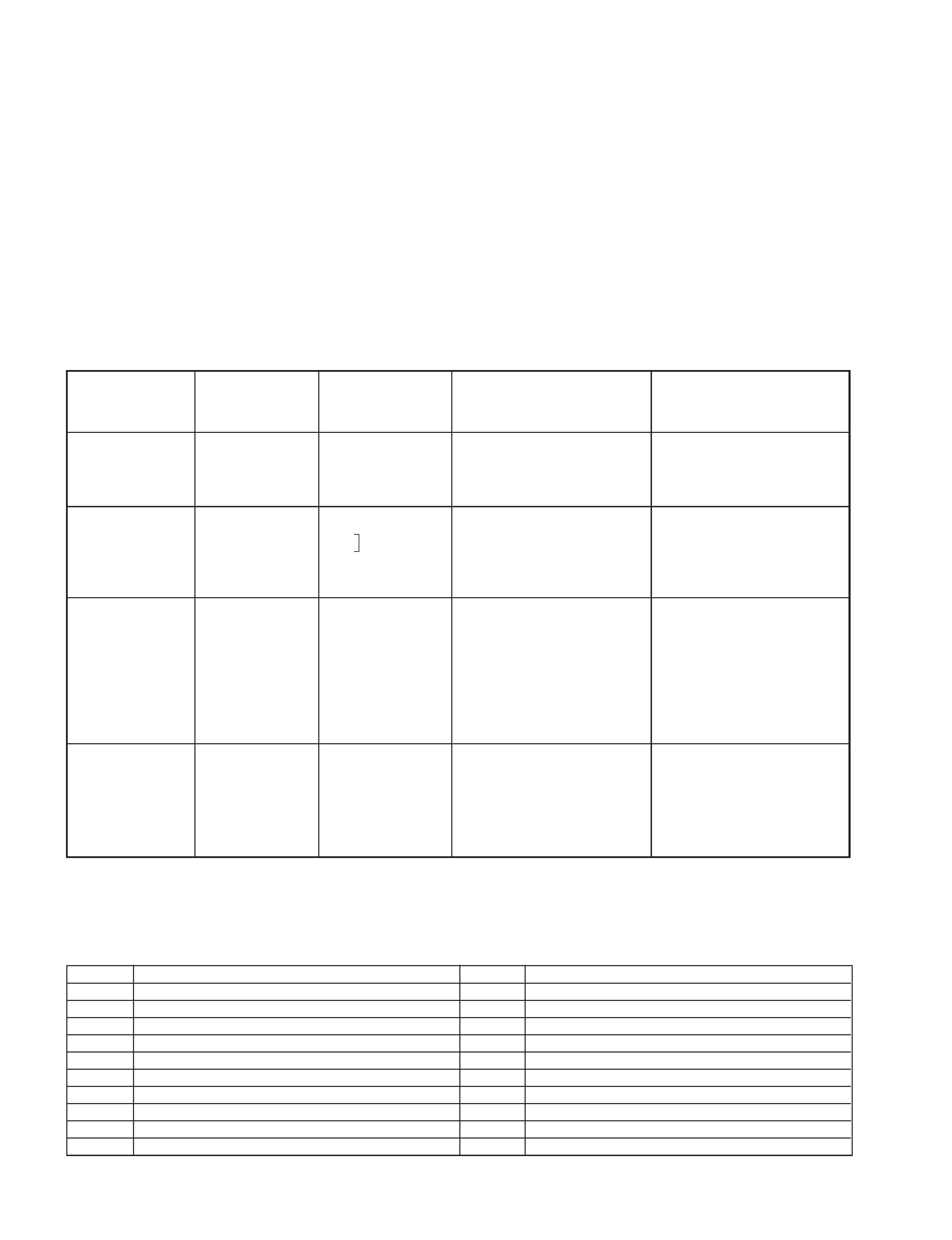
DIAGNOSTIC TEST INDICATORS
· When an errors occurs, the STANDBY lamp will flash a set number of times to indicate the possible cause of the problem.
If there is more than one error, the lamp will identify the first of the problem areas.
· Result for all of the following diagnostic items are displayed on screen. No error has occured if the screen displays a "0".
Diagnostic
Item
Description
· Power does not
turn on
No. of times
STANDBY lamp
flashes
Does not light
Self-diagnostic
display/Diagnostic
result
--
Probable
Cause
Location
· Power cord is not plugged
in.
· Fuse is burned out F1701
Detected
Symptoms
· Power does not come on.
· No power is supplied to the
TV.
· AC power supply is faulty.
Note 1: If a + B overcurrent is detected, stoppage of the vertical deflection is detected simultaneously.
The symptom that is diagnosed first by the microcontroller is displayed on the screen.
Note 2: Refer to screen (G2) Adjustment in section 3-4 of this manual.
SELF DIAGNOSTIC FUNCTION
· FBT
· Q802 (H OUT) shorted
2 : 0 or
2 : 1
4 : 1
2 times
4 times
5 times
· Vertical deflection
stopped
· White balance
failure (no
PICTURE)
· +B overcurrent
(OCP) or
overvoltage
(OVP)
· Has entered standby state
after horizontal raster.
· Vertical deflection pulse is
stopped.
· Horizontal deflection
stopped.
· Power line is shorted or
power supply is stopped.
4 : 0
or
4 : 1
· IC501
· IC301 !¢ pin
· IC606
· Q802 (H OUT) shorted
· Q803
· Q608
· R803 open
5 : 0
or
5 : 1
· On standby state.
· Load on power line is
shorted
(at the same time 4 : 1 on
display).
at the same
time
(Note 1)
·CRT
· IC301
· Q701 - Q717
(CVM board)
· G2 is improperly adjusted.
(Note 2)
· No raster is generated.
· CRT cathode current
detection reference pulse
output is small.
Code
Coutents
00h
NO EMG
10h
CAM encode NG during unloading
11h
CAM encode NG during unloading
12h
CAM encode NG at intial
20h
T reel NG during unloading
21h
S reel FG NG
22h
T reel FG NG
23h
S reel FG NG
24h
T reel FG NG at initial
25h
S reel FG NG at initial
Code
Coutents
30h
Capstan FG NG at initial
31h
Capstan FG NG
40h
Drum FG NG
41h
Drum FG NG at initial
42h
Drum FG NG
43h
Drum PG NG
44h
Drum PG NG
50h
DEW
60h
FL NG
70h
DEW eject NG
· VCR EMG code List
5
4.
SELF-DIAGNOSTIC SCREEN DISPLAY
· For errors with symptoms such as "power sometimes shuts off" or "screen sometimes goes out" that cannot be confirmed,
it is possible to bring up past occurances of failure for confirmation on the screen:
[To Bring Up Screen Test]
· In standby mode, press buttons on the remote commander sequentially in rapid succession as shown below:
[Screen display] / channel [5] / Sound volume [-] / Power ON u
Note that this differs from entering the service mode (mode volume [+]).
Self-Diagnosis screen display
5.
HANDLING OF SELF-DIAGNOSTIC SCREEN DISPLAY
· Since the diagnostic results displayed on the screen are not automatically cleared, always check the self-diagnostic
screen during repairs. When you have completed the repairs, clear the result display to "0".
· Unless the result display is cleared to "0", the self-diagnostic function will not be able to detect subsequent faults after
completion of the repairs.
[Clearing the result display]
· To clear the result display to "0", press buttons on the remote commander sequentially as shown below when the diagnos-
tic screen is being displayed.
· Pay attention when perform by the service mode, other all electric adjustment data will be rewrite.
Channel [8]
/ [0]
[Quitting Self-diagnostic screen]
· To quit the entire self-diagnostic screen, turn off the power switch on the remote commander or the main unit.
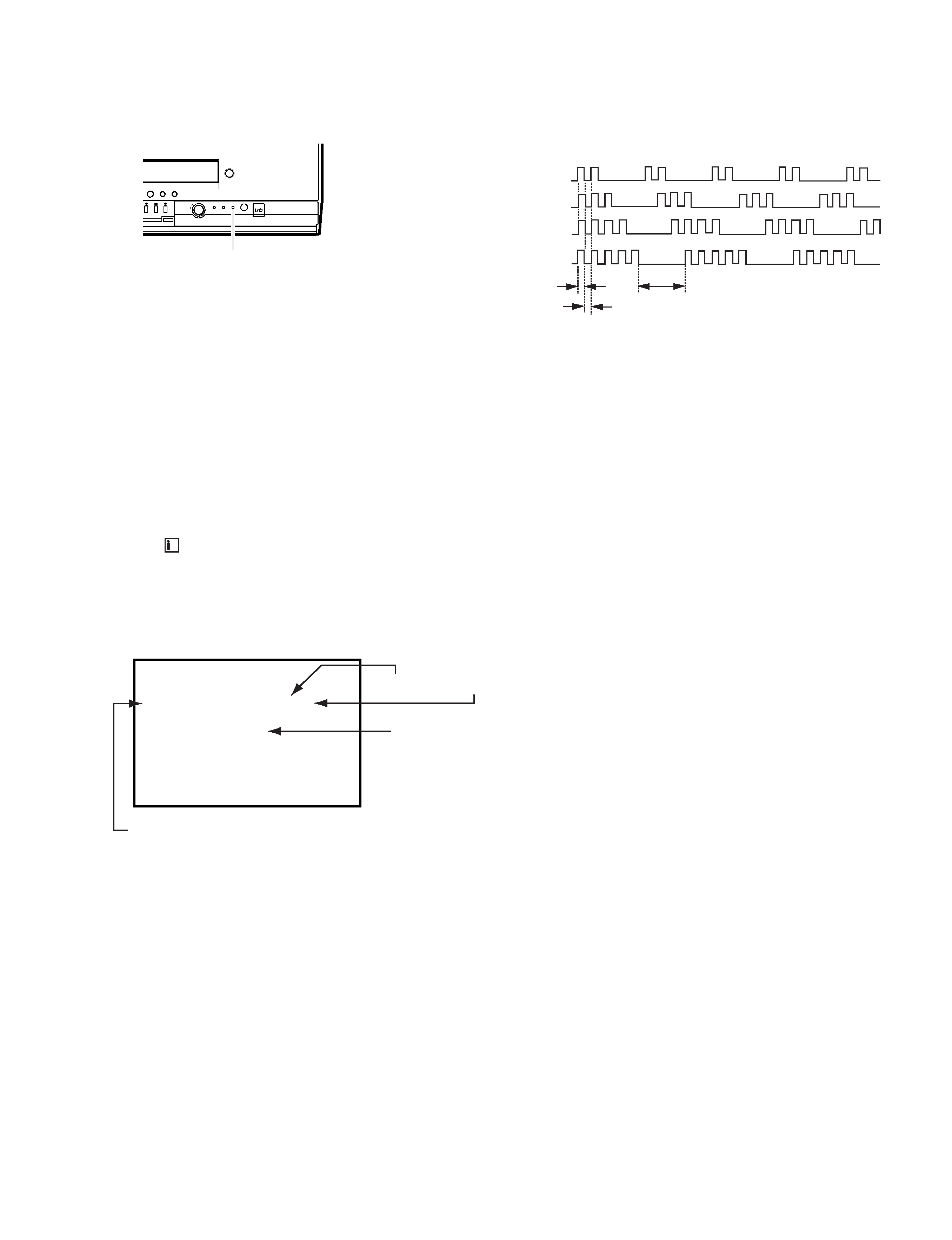
3.
DISPLAY OF STANDBY LIGHT FLASH COUNT
* One flash count is not used for self-diagnostic.
< Diagnostic Item >
· +B OCP/OVP
· White balance failure
STOPPING THE STANDBY FLASH
· Turn off the power switch on the TV main unit or unplug the power cord from the outlet to stop the STANDBY lamp from flashing.
· Vertical deflection stopped
2 times
4 times
5 times
Lamp ON 0.3 sec.
Lamp OFF 0.3 sec.
Lamp OFF 3.0 sec.
< Flash Count >
STANDBY lamp (RED)
PUSH
TEMER REC REC
P
Numeral "0" means that no fault has been detected.
Numeral "1" means a fault has been detected.
diagnostic item : result
SELF CHECK
VCR : -- --
1:
2 : 1
3 :
4 : 0
5 : 1
Note: Though "1: , 3:" indicated, not using.
EMG code.
+