RM-Y112
SERVICEMANUAL
US Model
Chassis No.
Canadian Model
Chassis No.
AP CHASSIS
Structure
Projection
system
tube
Projection lenses
Screen
material
Resolution
Projected picture size
Screen
Television
system
Channel
coverage
Antenna
MODELS OF THE SAME SERIES
KPR-41EXR95
SPECIFICATIONS
Screen and projector, rear projection type
Input jacks
3 picture tubes, 3 lenses, horizontal in-line
system
7 inch high-brightness monochrome
tubes (5.5 raster size), with optical coupling
and liquid cooling system
High performance, large-diameter
hybrid lens F 1 .O
Plastic lenticular, Plastic fresnel
760 lines
41 inches (measured diagonally)
2,000
American TV standards
VHF: 2
13
UHF: 14
69
Cable TV: 1
125
75 ohm external antenna
terminal for VHF/UHF
VIDEO IN 1
VIDEO IN
mini DIN)
Y: 1 Vp-p,
unbalanced,
sync negative
C: 0.286 Vp-p (Burst signal)
Video (phono jacks): 1 Vp-p,
unbalanced,
sync
negative
Audio (phono jacks):
500
(100% modulation)
Impedance: 47 kilohms
VIDEO IN 2 and 3
Video (phono jacks): 1 Vp-p,
unbalanced,
sync
negative
Audio (phono jacks):
500
(100% modulation)
Impedance: 47 kilohms
COLOR REAR VIDEO PROJECTOR
Output jacks
MONITOR OUT
S VIDEO MONITOR OUT
mini DIN)
1 Vp-p, 75-ohms
unbalanced,
sync
negative
Videp (phono jacks): 1 Vp-p,
unbalanced, sync negative
Audio (phono jacks): 500
(100%
modulation)
Impedance: 10 kilohms
AUDIO
OUT
(phono jacks)
More than 900
(100%
modulation)
at
the
maximum
volume setting (variable)
Impedance: 5 kilohms
AUDIO OUT
(phono jacks)
900
(100% modulation)
Impedance: 5 kilohms
Speaker
Two-way coaxial speaker system
Woofer 130 mm (5 inches) diameter
Tweeter 35 mm (1.4 inches) diameter
Speaker output
CENTER SPEAKER input
NORM. 30 W
MAX 50 W
Power requirements
Power
consumption
310 W (max
7 W (standby mode)
(CAUTION)
SHORT CIRCUIT THE ANODE OF THE PICTURE TUBE AND THE
ANODE CAP TO THE METAL CHASSIS, CRT SHIELD, OR CARBON
PAINTED ON THE CRT, AFTER REMOVING THE ANODE.
WARNING!!
AN ISOLATION TRANSFORMER SHOULD BE USED DURING ANY
SERVICE TO AVOID POSSIBLE SHOCK HAZARD, BECAUSE OF
LIVE CHASSIS.
THE CHASSIS OF THIS RECEIVER IS DIRECTLY CONNECTED TO
THE AC POWER LINE.
SAFETY-RELATED COMPONENT WARNING !!
COMPONENTS IDENTIFIED BY SHADING AND MARK
ON THE
SCHEMATIC DIAGRAMS, EXPLODED VIEWS AND IN THE PARTS
LIST ARE CRITICAL TO SAFE OPERATION. REPLACE THESE
COMPONENTS
WITH
SONY
PARTS
WHOSE
PART
NUMBERS
APPEAR AS SHOWN IN THIS MANUAL OR IN SUPPLEMENTS
PUBLISHED
BY
SONY.
CIRCUIT
ADJUSTMENTS
THAT
ARE
FOLLOW
THESE
PROCEDURES
WHENEVER
CRITICAL
COMPONENTS ARE REPLACED OR IMPROPER OPERATION IS
SUSPECTED.
Dimension (w/h/d)
x
x 20 inches)
Weight
72 kg (158 lb 12 oz)
Supplied accessories
Remote Commander
12 (1)
with 2 size AA (R6)
EVEREADY batteries
Optional accessories
UN mixer EAC-66
Connecting
cable
RK-74A
VMC-81
VCR Tray
Design and specifications are subject to change without notice.
SOUND RETRIEVAL SYSTEM
The
Sound Retrieval System is manufactured by Sony
Corporation under license from the Hughes Aircraft
Company, a subsidiary of GM Hughes Electronics. It is
covered
by U.S. Patent No.
Other U.S. and
foreign
patents
pending.
SOUND RETRIEVAL SYSTEM and
are
trademarks
of
the
Hughes
Aircraft
Company,
a
subsidiary
of GM Hughes Electronics.
(ATTENTION)
APRES
DECONNECTE
LE
CAP
DE
L'ANODE,
L'ANODE DU TUBE CATHODIQUE ET
DE L'ANODE DU CAP AU CHASSIS
DE
L'APPAREIL, OU AU COUCHE DE
SUR LE
TUBE
CATHODIQUE
OU
AU
DU
TUBE
CATHODIQUE.
ATTENTION!!
D'EVITER
TOUT
RISQUE
D'ELECTROCUTION
PROVENANT
D'UN
CHASSIS
TENSION,
UN
TRANSFORMATEUR
D'ISOLEMENT
ETRE
LE
CHASSIS
DE
CE
EST
L'ALIMENTATION
SECTEUR.
ATTENTION
AUX
COMPOSANTS
LES
COMPOSANTS
PAR UNE TRAME ET PAR
UNE MAPQUE
SUR LES
DE PRINCIPE, LES
VUES
ET LES
DE PIECES CONT D'UNE
IMPORTANCE
CRITIQUE
POUR
LA
DU
FONCTIONNEMENT.
NE
LES
REMPLACER
QUE
PAR
DES
COMPOSANTS SONY DONT LE
DE
EST
DANS
LE
MANUEL
OU
DANS
DES
SUPPLEMENTS
PAR SONY. LES
DE
CIRCUIT DONT L'IMPORTANCE EST CRITIQUE POUR LA
DU
FONCTIONNEMENT
SONT
IDENTIFIES
DANS
LE
MANUEL.
CES
LORS
DE
CHAQUE
REMPLACEMENT
DE
COMPOSANTS
CRITIQUES,
OU
LORSQU'UN
FONCTIONNEMENT
EST
SAFETY CHECK-OUT
(US Model only)
LEAKAGE
checks before releasing the set to the customer
Check the area of your repair for unsoldered or poorly-soldered
connections Check the entire board surface for solder splashes
and bridges
Check the interboard wiring
that no wires are "pinched"
or
contact
high-wattage
resistors
Check that all control knobs, shields, covers, ground straps, and
mounting hardware have been replaced Be absolutely certain that
you have replaced all the insulators
Look
for
unauthorized
replacement
parts,
particularly
transistors,
that were installed during a previous repair Point them out to the
customer and recommend their replacement
Look for parts which, though functioning, show obvious signs of
deterioration Point them out to the customer and recommend
their replacement
Check the line cord for
cracks and abrasion Recommend the
replacement of any such line cord to the customer
Check the condition of the monopofe antenna (if any)
Make sure the end is not broken off, and has the plastic cap on it
Point out the danger of impalement on a broken antenna to the
customer, and recommend the antenna's replacement
Check the B+ and HV to see they are at the values specified Make
sure your instruments are accurate, be suspicious of your HV
meter if sets always have low HV
Check the antenna terminals, metal trim,
knobs,
screws, and all other exposed metal parts for AC leakage Check
leakage as described below
To Exposed Metal
Parts on Set
0
AC
voltmeter
(0
Earth Ground
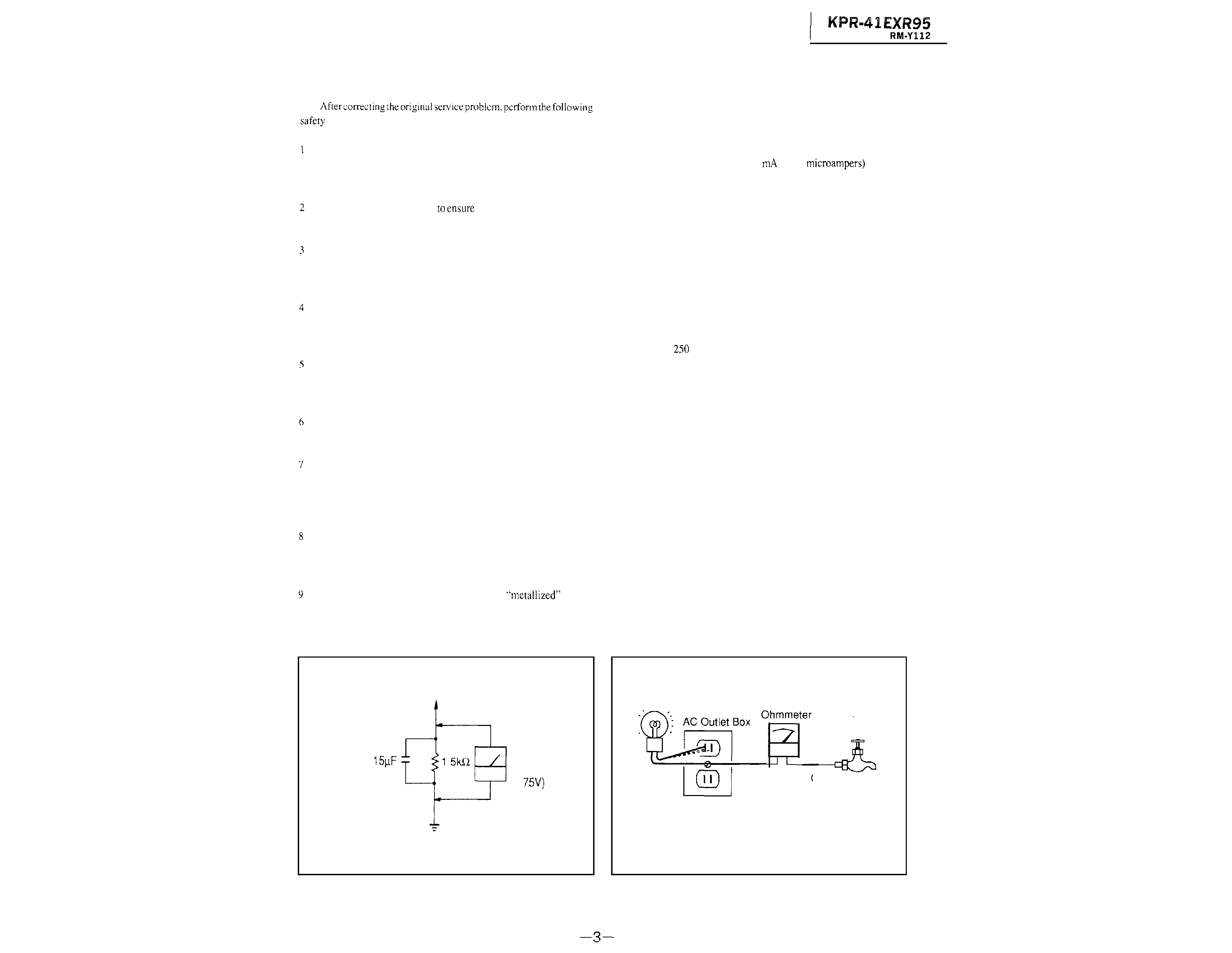
Fig A Using an AC voltmeter to check AC leakage
The AC leakage from any exposed metal part to earth ground and
from all exposed metal parts to any exposed metal part having a return
to chassis, must not exceed 0 5
(500
Leakage
current can be measured by any one of three methods
1.
A commercial leakage tester, such as the Simpson 229 or RCA
WT-540A Follow the manufacturers' instructions to use these
instruments
2
A battery-operated AC milliammeter The Data Precision 245
digital multimeter is suitable for this job
3
Measuring the voltage drop across a resistor by means of a VOM
or battery-operated AC voltmeter The "limit" indication is 0.75
V, so analog meters must have an accurate low-voltage scale The
Simpson
and Sanwa SH-63Trd are examples of a passive
VOM
thatissuitable
Nearlyall
batteryoperateddigitalmultimeters
that have a 2V AC range are suitable (See Fig A)
HOW TO FIND A GOOD EARTH GROUND
A cold-water pipe is guaranteed earth ground; the cover-plate
retaining screw on most AC outlet boxes is also at earth ground If the
retaining screw is to be used as your earth-ground, verify that it is at
ground by measuring the resistance between it and a coldwater pipe
with an ohmmeter The reading should be zero ohms If a cold-water
pipe is not accessible, connect a 60-100 watts trouble light (not a neon
lamp) between the hot side of the receptacle and the retaining screw.
Try both slots, if necessary, to locate the hot side of the line, the lamp
should light at normal brilliance if the screw is at ground potential (See
Fig. B)
Trouble Light
Cold-water Pipe
Fig B Checking for earth ground.
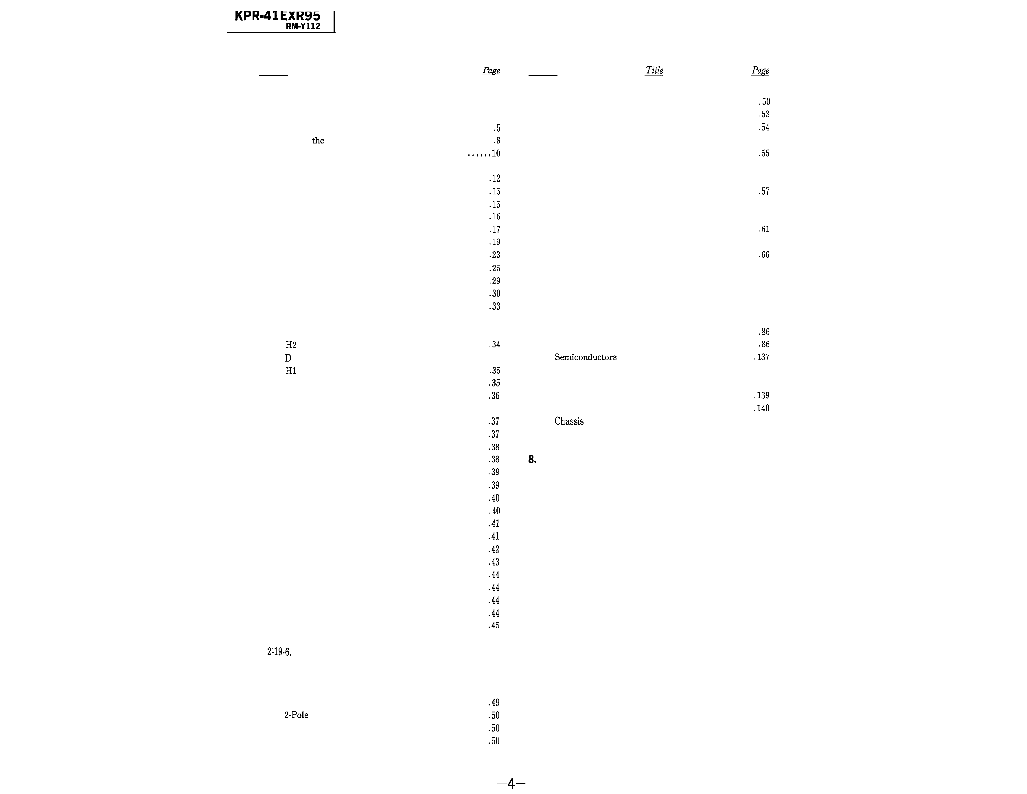
TABLE OF CONTENTS
Section
Title
Section
1. GENERAL
l-l.
Unpacking and Viewing Area ....................
5
1-2.
Locating Controls and Connectors ...............
1-3.
Using
On-Screen Menus .....................
1-4.
Adjusting Color Registration (Convergence)
1-5.
Setting CABLE ON or OFF. .................
.ll
l-6.
Presetting TV Channels. ........................
1-7.
Watching TV Programs
......................
1-8.
Using Convenient Features ....................
l-9.
Selecting a Picture and Sound Mode .............
l-10. Watching Two Pictures at Once (PINP) .........
l-11. Adjusting the Projection TV ...................
1-12.
Customizing the Screen Display .................
1-13.
Using Timer-Activated Functions ...............
1-14.
Setting Favorite Channel .......................
l-15. Using the Pre-Programmed Remote Commander .
l-16. Troubleshooting
...............................
3-6.
Green Picture Adjustments .............
3-7.
Green and Red Registration Adjustments.
.....
3-8.
Green and Blue Registration Adjustments .....
3-9.
Registration
Adjustments ......................
55
3-10.
White Balance Adjustments ....................
4. SAFETY RELATED ADJUSTMENTS
4-1.
Safety Related Adjustments ....................
5.
CIRCUIT
ADJUSTMENTS
5-1.
Electrical Adjustment By Remote Commander ...
5-2.
A Board Adjustments. .......................
63
5-3.
Pl Board Adjustments .......................
5-4.
G Board Adjustments ......................... 67
2.
DISASSEMBLY
2-1.
Board Removal .............................
2-2.
Board Removal
............................
..3 4
2-3.
Board Removal .............................
2-4.
Reflection Mirror Removal .....................
2-5.
Back Cover Removal ...........................
2-6.
Main Chassis Assy Removal
....................
36
2-7.
Service Position ...............................
2.8.
Sub Connector Panel Removal
.................
2-9.
Main Connector Panel Removal .................
2-10.
U Bracket Removal
...........................
2-11.
V Board Removal .............................
2-12.
N Bracket Removal
...........................
2-13.
G Board Removal ............................
2-14.
Mirror Cover Removal .......................
2-15.
Chassis Assy Removal .........................
2-16.
Picture Tube Removal .........................
2-17.
High-Voltage Cable Installation and Removal ...
2-18.
Connector Cable ..............................
2-19.
Repair of Chip Component Circuit Board
.......
2-19-1.
Points of Component Removal ...............
2-19-2.
Notes on Soldering for Chip Components .....
2-19-3.
Removal and Mounting of Components. ......
2-19-4.
Mini-Transistor.
............................
2-19-5. Two-Directional Flat Package IC ............ 46
Four-Directional Flat Package IC ............ 47
6. DIAGRAMS
6-1.
Block Diagrams ......................... 68
6-2.
Frame
Schematic
Diagram ..................
83
6-3.
Circuit Boards Location
..................
6-4.
Schematic Diagrams and Printed Wiring Boards .
6-5.
.............................
7. EXPLODED VIEWS
7-1.
Screen Frame and Contorol Panel ............
7-2.
Cabinet and Back Cover .....................
7-3.
.......................................
141
7-4.
Picture Tube ............................. ..14 2
ELECTRICAL PARTS LIST ..................
143
3. SET-UP ADJUSTMENTS
3-1.
Focus Lens Adjustments .....................
..4 9
3-2.
Deflection Yoke Position Adjustments ...........
3-3.
Magnet Adjustment ....................
3-4.
I-Pole Magnet Adjustment .....................
3-5.
De-Focns Adjustment
(Blue)
.................
l-l. UNPACKING AND VIEWING AREA
Carefully follow the
on
of the
to unpack the protection TV.
. The
are packed in the
the
away.
.
the
carton and
safely
the
N I"
future
Check to make sure that the
Included:
Remote Commander
(1)
2
AA (R6) EVEREADY
If the Remote Commander
contact your dealer.
Place
protection TV in a cool. dry place where
ventilation
at the
are not blocked.
Plug the
TV power cord
a" AC 120
power
For further
see p. 2.
SECTION 1
GENERAL
The operating instructions mentioned here are partial abstracts
from the Operating Instruction Manual. The page numbers of the
Operating Instruction Manual remein as in the manual.
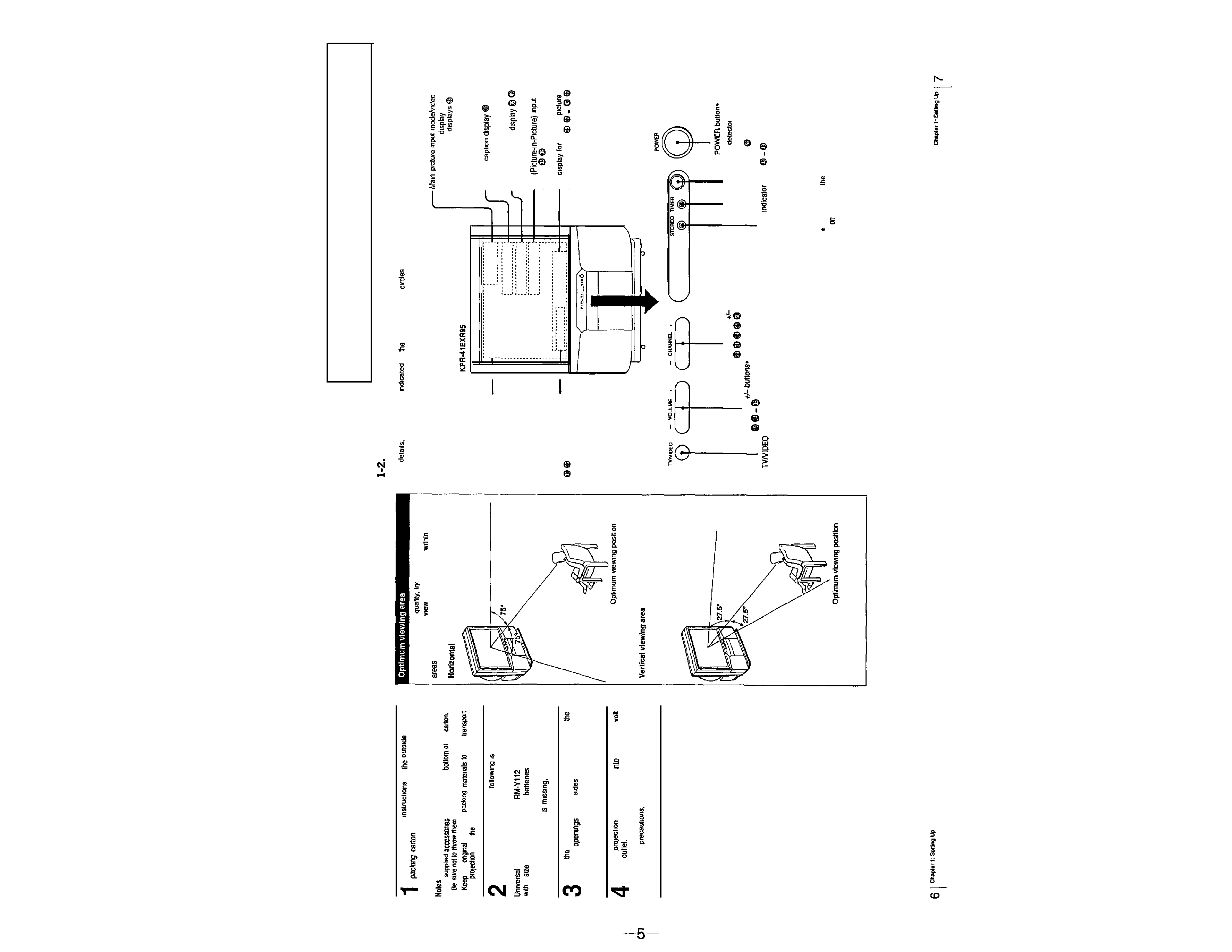
For the best picture
to position the protection
TV
SO that you can
the screen from
the
shown below.
viewing area
LOCATING CONTROLS AND CONNECTORS
For
see the pages
by
numbered black
l
Front
On-screen menu displays
CURRENT TIME displays
label
Channel number
SLEEP, MUTING
Channel
MTS (SAP) mode
PIP
mode
display
Ear
volume.
or
sound adjustment
CHANNEL
buttons
Remote control
I
VOLUME
TIMER indicator lamp
button*
STEREO
lamp
Buttons with
same function are also located
the Remote Commander (p. 10).