SERVICE MANUAL
MODEL
COMMANDER
DEST. CHASSIS NO.
Please file according to model size. ...
43
CHASSIS
48
53
MODEL
COMMANDER
DEST. CHASSIS NO.
61
RG-3
PROJECTION TV
KP-ES43HK1 RM-961
HK
SCC-P45B-A
KP-ES43ME1 RM-961
ME
SCC-P46B-A
KP-ES43MN1 RM-961
GE
SCC-P44D-A
KP-ES43SN1 RM-961
AUS
SCC-P47B-A
KP-ES48HK1 RM-961
HK
SCC-P45A-A
KP-ES48ME1 RM-961
ME
SCC-P46A-A
KP-ES48MN1 RM-961
GE
SCC-P44A-A
KP-ES48SN1 RM-961
AUS
SCC-P47A-A
RM-961
KP-ES43HK1/ME1/MN1/SN1
KP-ES53HK1/ME1/MN1/SN1
KP-ES61HK1/ME1/MN1/SN1
KP-ES53HK1 RM-961
HK
SCC-P45C-A
KP-ES53ME1 RM-961
ME
SCC-P46C-A
KP-ES53MN1 RM-961
GE
SCC-P44B-A
KP-ES53SN1 RM-961
AUS
SCC-P47C-A
KP-ES61HK1 RM-961
HK
SCC-P45D-A
KP-ES61ME1 RM-961
ME
SCC-P46D-A
KP-ES61MN1 RM-961
GE
SCC-P44C-A
KP-ES61SN1 RM-961
AUS
SCC-P47D-A
KP-ES48HK1/ME1/MN1/SN1
2
KP- ES43HK1/ME1/MN1/SN1, ES48HK1/ME1/MN1/SN1,
ES53HK1/ME1/MN1/SN1, ES61HK1/ME1/MN1/SN1KRM-961
CAUTION
SHORT CIRCUIT THE ANODE OF HTE PICTURE TUBE
AND THE ANODE CAP TO THE METAL CHASSIS, CRT
SHIELD, OR CARBON PAINTED ON THE CRT, AFTER
REMOVING THE ANODE.
SAFETY-RELATED COMPONENT WARNING!!
COMPONENTS IDENTIFIED BY SHADING AND MARK
! ON THE SCHEMATIC DIAGRAMS, EXPLODED
VIEWS AND IN THE PARTS LIST ARE CRITICAL TO
SAFE OPERATION. REPLACE THESE COMPONENTS
WITH SONY PARTS WHOSE PART NUMBERS AP-
PEAR AS SHOWN IN THIS MANUAL OR IN SUPPLE-
MENTS PUBLISHED BY SONY.
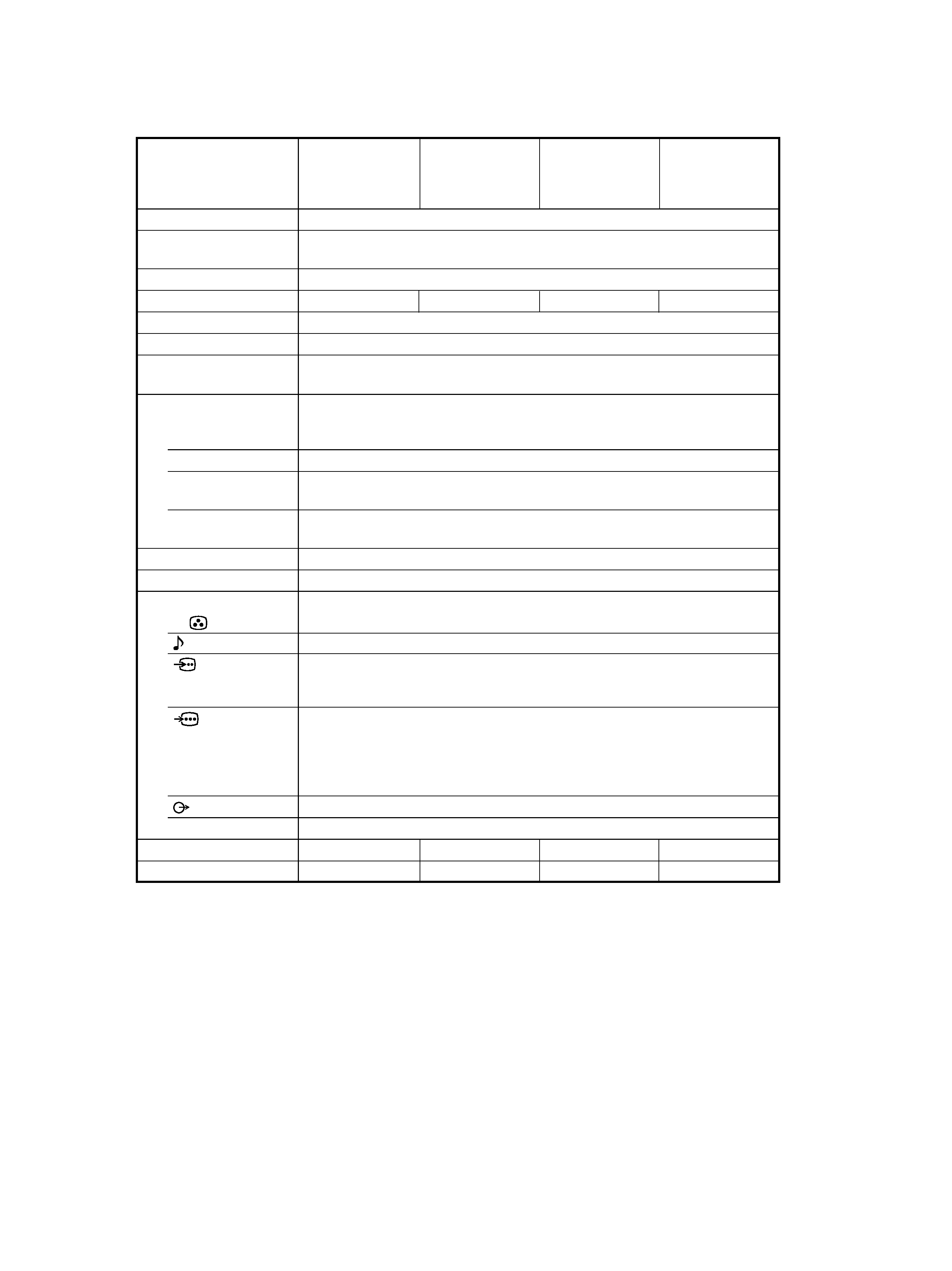
SPECIFICATIONS
Projection system
Picture tube
Projection lenses
Screen size
Television system
Color system
Stereo/Bilingual
system
Channel coverage
B/G
I
D/K
M
8
(Antenna)
Audio output (Speaker)
Number of terminal
(Video)
(Audio)
(S Video)
(Component
Video)
i
(Headphones)
Dimensions (w/h/d, mm)
Mass (kg)
3 picture tubes, 3 lenses, horizontal inline system
7 inch high-brightnes monochorome tubes (6.3 raster size), with optical coupling
and liquidcooling system
High performance, large-diameter highbrid lens F1.0
61 inches
53 inches
48 inches
43 inches
B/G, I, D/K, M
PAL, PAL 60, SECAM, NTSC4.43, NTSC3.58
NICAM Stereo/Bilingual B/G, I;
A2 Stereo/Bilingual (German) B/G
VHF : E2 to E12 / UHF : E21 to E69 / CATV : S01 to
S03, S1 to S41
UHF : B21 to B68 / CATV : S01 to S03, S1 to S41
VHF : C1 to C12, R1 to R12 / UHF : C13 to C57, R21
to R60 / CATV : S01 to S03, S1 to S41, Z1 to Z39
VHF : A2 to A13 / UHF : A14 to A79/
CATV : A-8 to A-2, A to W+4, W+6 to W+84
75-ohm external terminal
13W + 13W, ( 10% distortion)
Input: 4 Output: 1
Phono jacks; 1 Vp-p, 75 ohms
Input: 4 Output: 1
Phono jacks; 500 mVrms
Input: 2
Y: 1 Vp-p, 75 ohms,
unbalanced, sync negative
C: 0.286 Vp-p, 75 ohms
Input: 1
Phono jacks
Y: 1 Vp-p, 75 ohms, sync negative
CB/B-Y: 0.7 Vp-p, 75 ohms
CR/R-Y: 0.7 Vp-p, 75 ohms
Audio: 500 mVrms
Output: 1
Phono jack; 500 mVrms
Output: 1
Stereo minijack
1372
× 1542 × 661.5
1218
× 1423 × 623 1091 × 1336 × 580
966
× 1078 × 532
90
76
68
61
Design and specifications are subject to change without notice.
KP-ES61MN1/
KP-ES61HK1/
KP-ES61ME1/
KP-ES61SN1
KP-ES53MN1/
KP-ES53HK1/
KP-ES53ME1/
KP-ES53SN1
KP-ES48MN1/
KP-ES48HK1/
KP-ES48ME1/
KP-ES48SN1
KP-ES43MN1/
KP-ES43HK1/
KP-ES43ME1/
KP-ES43SN1
Power requirements
110 V 240 V (For KP-ES61MN1/KP-ES53MN1/KP-ES48MN1/KP-ES43MN1/
KP-ES61ME1/KP-ES53ME1/KP-ES48ME1/KP-ES43ME1)
220 V 240 V (For KP-ES61HK1/KP-ES53HK1/KP-ES48HK1/KP-ES43HK1/
KP-ES61SN1/KP-ES53SN1/KP-ES48SN1/KP-ES43SN1)
Power consumption (W)
270 W (For KP-ES61MN1/KP-ES53MN1/KP-ES48MN1/KP-ES43MN1/
KP-ES61ME1/KP-ES53ME1/KP-ES48ME1/KP-ES43ME1)
255 W (For KP-ES61HK1/KP-ES53HK1/KP-ES48HK1/KP-ES43HK1/
KP-ES61SN1/KP-ES53SN1/KP-ES48SN1/KP-ES43SN1)

3
KP- ES43HK1/ME1/MN1/SN1, ES48HK1/ME1/MN1/SN1,
ES53HK1/ME1/MN1/SN1, ES61HK1/ME1/MN1/SN1KRM-961
1. SELF DIAGNOSIS FUNCTION
1-1.
Diagnostic Test Indicators .................................
5
1-2.
Display of STANDBY/TIMER
Light Flash Count ...............................................
6
1-3.
Stopping the STANDBY/TIMER Flash ............
6
1-4.
Self-Diagnostic Screen Display .........................
7
1-5.
Handling of Self-Diagnostic
Screen Display ....................................................
7
1-6.
Self-Diagnostic Circuit ......................................
8
2. GENERAL .................................................................
9
3. DISASSEMBLY
3-1.
Rear Board Removal .........................................
33
3-2.
Main Bracket Block Removal ...........................
34
3-3.
Service Position .................................................
34
3-4.
Control Panel Block and Resistor Assembly
(Focus Pack) Removal ......................................
35
3-5.
Beznet Block Removal ......................................
36
3-6.
Chassis Block Removal ......................................
37
3-7.
Terminal Board Removal ...................................
38
3-8.
BD, DS, D Boards Removal ..............................
38
3-9.
G, G1 Board Removal ........................................
39
3-10. J1, B3, E, M1 Boards Removal ..........................
39
3-11. A1 Board Removal .............................................
40
3-12. High-Voltage Cable Removal and Installation ..
40
3-13. Picture Tube Removal ........................................
40
4. SET-UP ADJUSTMENTS
4-1.
Screen Voltage Adjustment
(Rough Alignment) ...........................................
41
4-2.
Screen (G2) Adjustment ....................................
41
4-3.
Focus Rough Adjustment ..................................
41
4-4.
Deflection Yoke Tilt Adjustment ......................
41
4-5.
2-Pole Magnet Adjustment ................................
42
4-6.
4-Pole Magnet Adjustment ................................
42
4-7.
Green, Red and Blue Focus Adjustment
4-7-1. Green, Red and Blue Lens Focus
Adjustment ....................................................
42
4-7-2. Green, Red and Blue Electrical Focus
Adjustment ....................................................
42
5. SAFETY RELATED ADJUSTMENT
5-1.
HV Hold-Down Adjustment .............................
43
TABLE OF CONTENTS
6. ELECTRICAL ADJUSTMENTS
6-1.
Adjustments with Commander
6-1-1. How to Select Each Mode .............................
44
6-1-2. How to Enter Service Mode ..........................
45
6-1-3. Method of Cancellation
from Service Mode ........................................
45
6-1-4. How to Adjustments ......................................
45
6-1-5. How to Write the Data ...................................
45
6-1-6. Memory Write Confirmation Method ...........
45
6-2.
Service List .........................................................
46
6-3.
Picture Quality Adjustment
6-3-1. Preparation .....................................................
60
6-3-2. NTSC Video Input .........................................
60
6-3-3. NTSC RF Input ..............................................
61
6-3-4. PAL Video Input ............................................
61
6-3-5. PAL RF Input .................................................
62
6-4.
Color Offset (53, 61 inch model only)
6-4-1. 50 Hz (PAL) TV Mode ..................................
62
6-4-2. 50 Hz (PAL) Video Mode .............................
62
6-4-3. 60 Hz (NTSC) TV Mode ...............................
62
6-4-4. 60 Hz (NTSC) Video Mode ...........................
62
6-5.
Registration Adjustment
6-5-1. Setup for Adjustment .....................................
63
6-5-2. Method of Main Deflection Adjustment .......
63
6-5-3. Operation Method
for Projector Engine (PJE) Mode ..................
64
6-5-4. Method of Projector Engine Adjustment
(Sub Deflection Adjustment) .........................
65
6-5-5. Deflection Adjustment ...................................
67
6-6.
Auto Convergence Setting .................................
73
6-7.
White Balance Adjustment ................................
73
6-8.
Auto Convergence Error Code List ...................
74
Section
Title
Page
Section
Title
Page

4
KP- ES43HK1/ME1/MN1/SN1, ES48HK1/ME1/MN1/SN1,
ES53HK1/ME1/MN1/SN1, ES61HK1/ME1/MN1/SN1KRM-961
7. DIAGRAMS
7-1.
Block Diagrams ..................................................
75
7-2.
Frame Schematic Diagram (1) (KP-ES43) ........ 103
Frame Schematic Diagram (2)
(KP-ES48/53/61) ................................................ 106
7-3.
Circuit Boards Location ..................................... 109
7-4.
Schematic Diagrams and Printed Wiring
Boards ................................................................. 109
(1)
Schematic Diagram of J1 (1/2) Board ............... 112
(2)
Schematic Diagram of J1 (2/2) Board .............. 115
(3)
Schematic Diagram of A1 Board ...................... 118
(4)
Schematic Diagram of B3 (1/5) Board .............. 124
(5)
Schematic Diagram of B3 (2/5) Board .............. 127
(6)
Schematic Diagram of B3 (3/5) Board .............. 130
(7)
Schematic Diagram of B3 (4/5) Board .............. 133
(8)
Schematic Diagram of B3 (5/5) Board .............. 135
(9)
Schematic Diagram of E Board ......................... 137
(10) Schematic Diagram of M1 Board ...................... 140
(11) Schematic Diagrams of H1, H2 Boards
(KP-ES43) .......................................................... 143
(12) Schematic Diagrams of H1, H2 and H3 Boards
(KP-ES48/53/61) ................................................ 145
(13) Schematic Diagram of DS Board ....................... 147
(14) Schematic Diagram of D Board ......................... 151
(15) Schematic Diagram of BD (1/2) Board ............. 154
(16) Schematic Diagram of BD (2/2) Board ............. 157
(17) Schematic Diagrams of CR, CG, CB, ZR, ZG
and ZB Boards .................................................... 163
(18) Schematic Diagram of G Board (AUS/HK) ...... 166
(19) Schematic Diagram of G1 Board (GE/ME) ....... 169
7-5.
Semiconductors ................................................. 175
7-6.
IC Block Diagrams ............................................. 178
8. EXPLODED VIEWS
8-1.
Screen and Cover Block (KP-ES43) ................. 181
8-2.
Control Panel and Cabinet Block (KP-ES43) .. 182
8-3.
Screen and Cover Block (KP-ES48) .................. 183
8-4.
Control Panel and Cabinet Block (KP-ES48) ... 184
8-5.
Screen and Cover Block (KP-ES53) .................. 185
8-6.
Control Panel and Cabinet Block (KP-ES53) ... 186
8-7.
Screen and Cover Block (KP-ES61) .................. 187
8-8.
Control Panel and Cabinet Block (KP-ES61) ... 188
8-9.
Main Bracket Block ........................................... 189
8-10. Picture Tube Block ............................................. 190
9. ELECTRICAL PARTS LIST ............................ 191
Section
Title
Page
5
KP- ES43HK1/ME1/MN1/SN1, ES48HK1/ME1/MN1/SN1,
ES53HK1/ME1/MN1/SN1, ES61HK1/ME1/MN1/SN1KRM-961
SECTION 1
SELF DIAGNOSIS FUNCTION
The unit in this manual contain a self-diagnostic function. If an error occurs, the STANDBY/TIMER lamp will automatically begin to
flash.
The number of times the lamp flashes translates to a probable source of the problem. A definition of the STANDBY/TIMER lamp flash
indicators is listed in the instruction manual for the user's knowledge and reference. If an error symptom cannot be reproduced, the
remote commander can be used to review the failure occurrence data stored in memory to reveal past problems and how often these
problems occur.
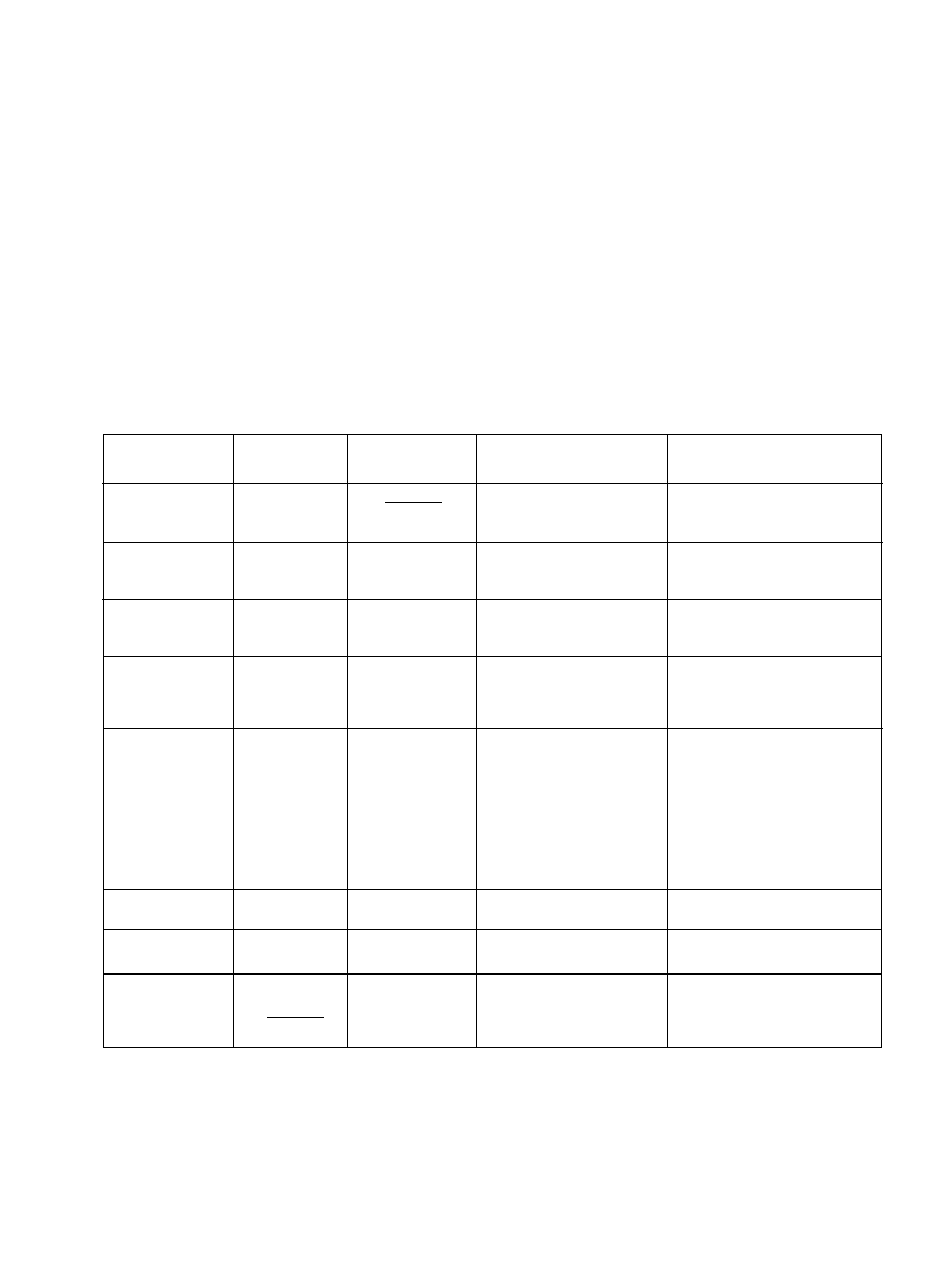
1-1. DIAGNOSTIC TEST INDICATORS
When an errors occurs, the STANDBY/TIMER lamp will flash a set number of times to indicate the possible cause of the problem. If
there is more than one error, the lamp will identify the first of the problem areas.
Result for all of the following diagnostic items are displayed on screen. No error has occurred if the screen displays a "0".
002:000 or
002:001 ~ 255
003:000 or
003:001 ~ 255
004:000 or
004:001 ~ 255
005:000 or
005:001 ~ 255
006:000 or
006:001 ~ 255
007:000 or
007:001 ~ 255
101:000 or
101:001 ~ 255
No. of times
STANDBY/TIMER
lamp flashes
Detected Symptoms
Diagnostic
Item
Description
· Power does not
turn on
· +B overcurrent
(OCP)
· +B overvoltage
(OVP)
· Vertical deflection
failure
· White balance
failure
(no PICTURE)
· High Voltage
failure
· Audio Protection
· Micro reset
Self-diagnostic
display/
Diagnostic result
Probable Cause Location
Does not light
2 times
3 times
4 times
5 times
6 times
7 times
· Power cord is not plugged in.
· Fuse (F6001) is burned out.
(G, G1 board)
· H. OUT Q5104 is shorted.
· H. LIN Q5105 is shorted.
(D board)
· IC6002 faulty.
· 10.5 V is not supplied.
(G, G1 board)
· V. OUT IC5302 faulty.
· R5340 open
· R5341 open
(D board)
· G2 is improperly adjusted.
(Note 1)
· CRT problem.
· Video OUT IC7101 (CR
board), IC7201 (CG board),
IC7301 (CB board) are faulty.
· IC8306 (J1 board) and
IC4301 (E board) are faulty.
· No connection E board to CR
board.
· IC6301 (G, G1 bard) faulty.
· Power supply fails.
· IC1101 (A1 board) faulty.
·Discharge CRT
(CR, CG, CB boards)
· Static discharge
· External noise
· Power does not come on.
· No power is supplied to the PJ.
· AC power supply is faulty.
· Power does not come on.
· Load on power line is shorted.
· Power does not come on.
· Vertical deflection pulse is
stopped.
· Vertical size is too small.
· Vertical deflection stopped.
· No raster is generated.
· CRT cathode current detection
reference pulse output is small.
· +135 V is too high.
· There is picture but speaker
does not release sound.
· Power is shut down shortly,
after this return back to normal.
· Detect Micro latch up.
Note 1 : Refer to screen (G2) adjustment in section 4-2 of this manual.