
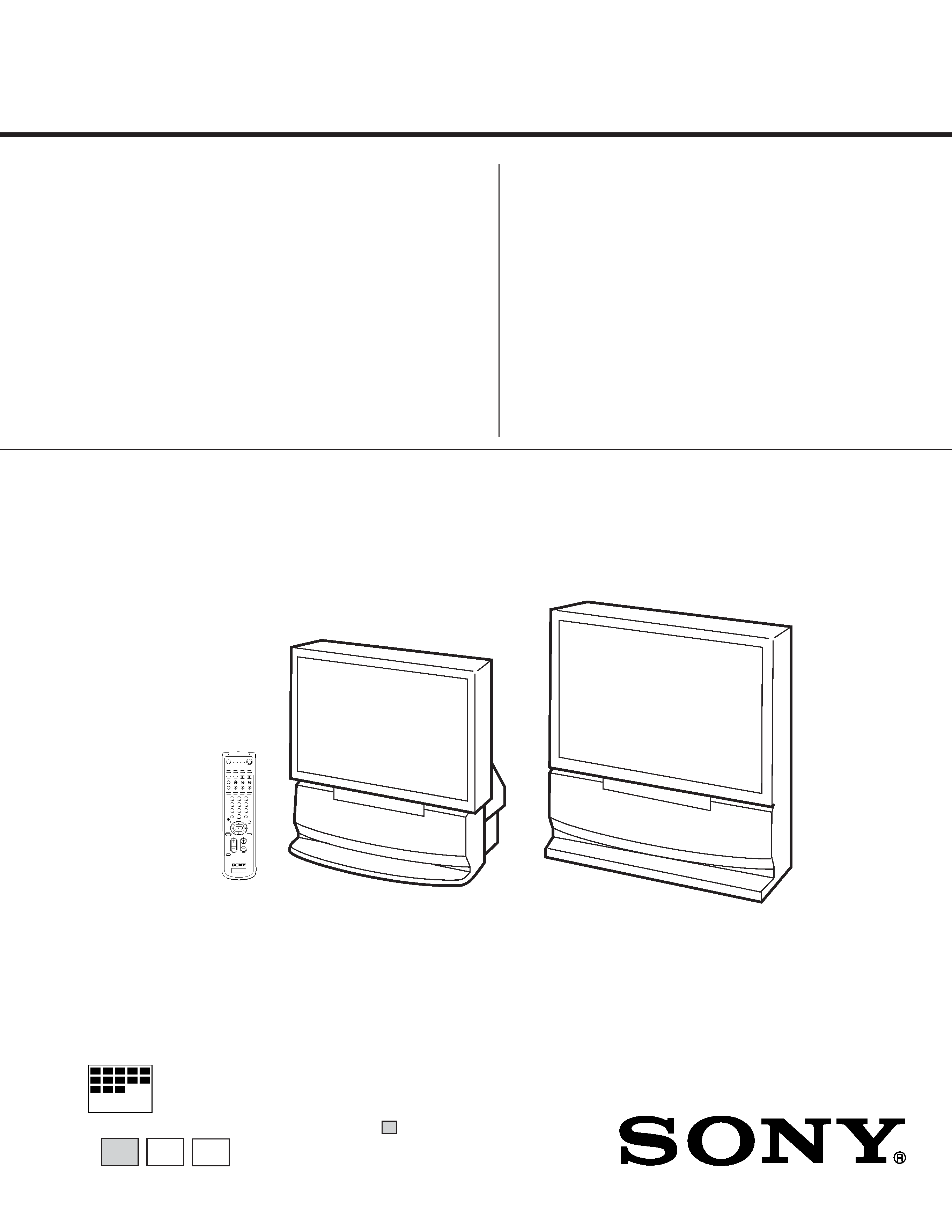
PROJECTION TV
SERVICE MANUAL
RA-2A CHASSIS
MODEL NAME
REMOTE COMMANDER
DESTINATION
CHASSIS NO.
9-965-221-03
KP-48V75
RM-Y903
US
SCC-N65G-A
KP-48V75
RM-Y903
CND
SCC-N66G-A
KP-53V75
RM-Y903
US
SCC-N65F-A
KP-53V75
RM-Y903
CND
SCC-N66F-A
KP-61V75
RM-Y903
US
SCC-N65H-A
KP-61V75
RM-Y903
CND
SCC-N66H-A
HISTORY INFORMATION FOR THE FOLLOWING MANUAL:
ORIGINAL MANUAL ISSUE DATE: 5/1998
ALL REVISIONS AND UPDATES TO THE ORIGINAL MANUAL ARE APPENDED TO THE END OF THE PDF FILE.
REVISION DATE
REVISION TYPE
SUBJECT
5/1998
No revisions or updates are applicable at this time.
7/1998
Correction - 1
Parts Change (Page 103, 123, 124)
5/2002
Correction - 2
Part Number Correction on Exploded View (Page 102)
CHASSIS
RA-2A
SERVICE MANUAL
MODEL
COMMANDER
DEST. CHASSIS NO.
KP-48V75
RM-Y903
US
SCC-N65G-A
KP-48V75
RM-Y903
Canadian
SCC-N66G-A
KP-53V75
RM-Y903
US
SCC-N65F-A
KP-53V75
RM-Y903
Canadian
SCC-N66F-A
MODEL
COMMANDER
DEST. CHASSIS NO.
KP-61V75
RM-Y903
US
SCC-N65H-A
KP-61V75
RM-Y903
Canadian
SCC-N66H-A
MICROFILM
48
PROJECTION TV
53
61
Please file according to model size. .......
KP-61V75
RM-Y903
KP-48V75/53V75
1
2
3
4
5
6
7
8
0
9

2
KP-48V75/53V75/61V75
RM-Y903
RM-Y903
RM-Y903
SPECIFICATIONS
Projection system
3 picture tubes, 3 lenses,
horizontal in-line system
Picture tube
7 inch high-brightness
monochrome tubes (6.3 raster
size), with optical coupling and
liquid cooling system
Projection lenses
High performance, large-
diameter hybrid lens F1.1
Screen size (measured diagonally)
Speaker
Full range speaker 100 mm (3.9
inches) diameter
Speaker output
15 W x 2
CENTER SPEAKER IN : 30 W x
1 (NORMAL), 60W x 1 (MAX),
16 ohms
Power requirement
120 V, 60 Hz
Power consumption
175 W
Standby mode: 2.5 W
KP-48V75
48 inches
KP-53V75
53 inches
KP-61V75
61 inches
Television system
American TV standards
Channel coverage
VHF: 2 13 / UHF: 14 69 /
CATV: 1 125
Antenna
75 ohm external antenna
terminal for VHF/UHF
Inputs/output
VIDEO IN 1
VIDEO 2 INPUT
VIDEO IN 3
S VIDEO (4-pin mini DIN):
Y: 1 Vp-p, 75-ohms
unbalanced, sync negative
C: 0.286 Vp-p (Burst signal)
75 ohms
VIDEO (phono jack): 1 Vp-p,
75-ohms unbalanced, sync
negative
AUDIO (phono jacks): 500
mVrms (100% modulation)
Impedance : 47 kilohms
VIDEO IN 4
Y: 1 Vp-p, 75-ohms, sync
negative
CB: 0.7 Vp-p, 75-ohms
CR: 0.7 Vp-p, 75-ohms
TV OUT
MONITOR OUT
VIDEO (phono jack): 1 Vp-p,
75-ohms unbalanced, sync
negative
AUDIO (phono jacks): 500 mVrms
(100% modulation),
Impedance: 10 kilohms
AUDIO (VAR/FIX) OUT
(phono jacks): 500mVrms (100%
modulation)
Impedance: 5 kilohms
KP-48V75
KP-53V75
KP-61V75
Mass
70 kg
(154 lbs 5 oz)
73 kg
(161 lbs 2 oz)
124 kg
(273 lbs 9 oz)
Dimensions (W/H/D)
1,106 x 1,337 x 571 mm
(43 5/8 x 52 5/8 x 22 1/2 inches)
1,218 x 1,413 x 614 mm
(48 x 55 5/8 x 24 1/4 inches)
1,338 x 1,506 x 642 mm
(52 3/4 x 59 3/8 x 25 3/8 inches)
Supplied accessories Remote control RM-Y903 (1)
Size AA (R6) battery (2)
Optional accessories
U/V mixer EAC-66
Connecting cables RK-74A, RK-G34,
VMC-10HG, VMC-720M, VMC-
810S/820S, YC-15V/30V
Design and specifications are subject to change without notice.
SRS (r)® (SOUND RETRIEVAL SYSTEM)
The SRS (r)® (SOUND RETRIEVAL SYSTEM) is
manufactured by Sony Corporation under license from
SRS Labs, Inc. It is covered by U.S. Patent No.
4,748,669. Other U.S. and foreign patents pendeing.
The word `SRS' and the SRS symbol (r) are
registered trademarks of SRS Labs, Inc.
3
KP-48V75/53V75/61V75
RM-Y903
RM-Y903
RM-Y903
SAFETY CHECK-OUT
( US model only )
After correcting the original service problem, perfom the follow-
ing safety checks before releasing the set to the customer:
l.
Check the area of your repair for unsoldered or poorly-sol-
dered connections. Check the entire board surface for solder
splashes and bridges.
2. Check the interboard wiring to ensure that no wires are
"pinched" or contact high-wattage resistors.
3. Check that all control knobs, shields, covers, ground straps,
and mounting hardware have been replaced. Be absolutely
certain that you have replaced all the insulators.
4. Look for unauthorized replacement parts, particularly tran-
sistors, that were installed during a previous repair. Point them
out to the customer and recommend their replacement.
5. Look for parts which, through functioning, show obvious
signs of deterioration. Point them out to the customer and
recom mend their replacement.
6. Check the line cords for cracks and abrasion. Recommend
the replacement of any such line cord to the customer.
7. Check the condition of the monopole antenna (if any). Make
sure the end is not broken off, and has the plastic cap on it.
Point out the danger of impalement on a broken antenna to
the customer, and recommend the antenna's replacement.
8. Check the B+ and HV to see they are at the values specified.
Make sure your instruments are accurate;be suspicious of
your HV meter if sets always have low HV.
9. Check the antenna temminals, metal trim, "metallized" knobs,
screws, and all other exposed metal parts for AC leakage.
Check leakage as described below.
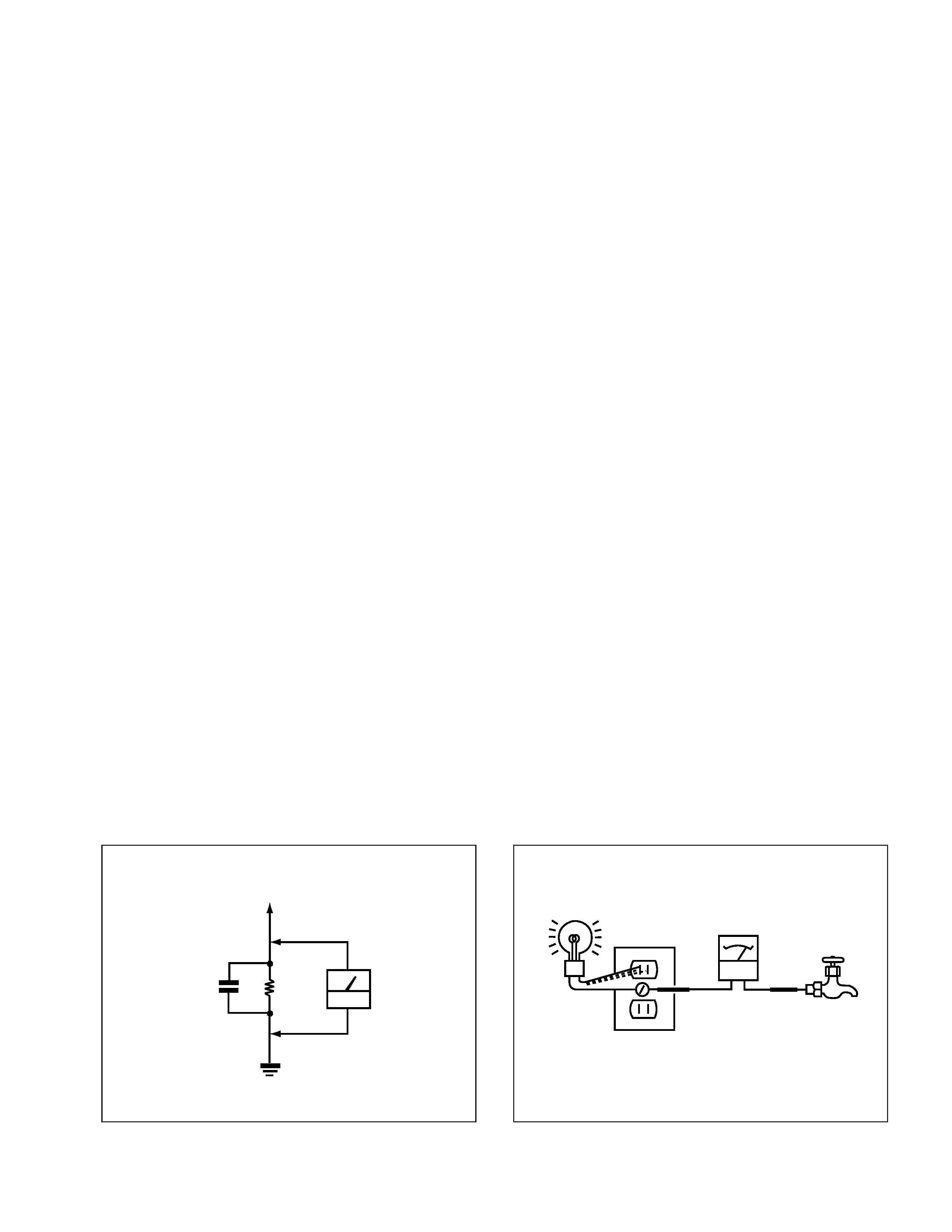
LEAKAGE TEST
The AC leakage from any exposed metal part to earth ground and
from all exposed metal parts to any exposed metal part having a
return to chassis, must not exceed 0.5mA (500 microampers) . Leak-
age current can be measured by any one of three methods.
1. A commercial leakage tester, such as the Simpson 229 or
RCA WT-540A. Follow the manufacturers' instructions to
usc these instruments.
2. A battery-operated AC milliammeter. The Data Precision 245
digital multimeter is suitable for this job.
3. Measuring the voltage drop across a resistor by means of a
VOM or battery-operated AC voltmeter. The "limit" indica-
tion is 0.75V, so analog meters must have an accurate low-
voltage scale. The Simpson 250 and Sanwa SH-63Trd are
examples of a passive VOM that is suitable. NearIy all bat-
tery operated digital multimeters that have a 2V AC range
are suitable. (See Fig. A)
HOW TO FIND A GOOD EARTH GROUND
A cold-water pipe is guaranteed earth ground;the cover-plate re-
taining screw on most AC outlet boxes is also at earth ground. If
the retaining screw is to be used as your earth-ground, verify that it
is at ground by measuring the resistance between it and a cold-
water pipe with an ohmmeter. The reading should be zero ohms. If
a cold-water pipe is not accessible, connect a 60-l00 watts trouble
light (not a neon lamp) between the hot side of the receptacle and
the retaining screw. Try both slots, if necessary, to locate the hot
side of the line, the lamp should light at normal brilliance if the
screw is at ground potential. (See Fig. B)
To Exposed Metal
Parts on Set
0.15
µ F
1.5k
AC
voltmeter
(0.75V)
Earth Ground
Fig. A. Using an AC voltmeter to check AC leakage.
Fig. B. Checking for earth ground.
Ohmmeter
Cold-water Pipe
Trouble Light
AC Outlet Box

4
KP-48V75/53V75/61V75
RM-Y903
RM-Y903
RM-Y903
TABLE OF CONTENTS
Section
Title
Page
1. GENERAL
Step 1 : Installing the projection TV ................................................... 5
Step 2 : Hook up .................................................................................. 5
Step 3 : Setting up the remote control ............................................... 12
Step 4 : Setting up the projection TV automatically (AUTO SET UP) .. 13
Changing the menu larguage ............................................................. 15
Watching the TV ................................................................................ 15
Watching tow programs at one time-PIP/P&P(Twin ViewTM)/ CH INDEX . 16
Freezing the picture (FREEZE) ......................................................... 17
Adjusting the picture (VIDEO) ......................................................... 17
Adjusting the color temperature (TRINITONE) ............................... 18
Selecting the video mode (VIDEO) .................................................. 18
Adjusting the sound (AUDIO) .......................................................... 18
Using audio effect (EFFECT) ........................................................... 19
Selecting stereo or bilingual programs (MTS) .................................. 19
Setting the speaker switch (SPEAKER) ............................................ 20
Setting audio out (AUDIO OUT) ...................................................... 20
Setting daylight saving time (DAYLIGHT SAVING) ...................... 20
Setting the clock (CURRENT TIME SET) ....................................... 21
Setting the timer to turn the projection TV on and off (ON/OFF TIMER) ... 21
Customizing the channel names (CHANNEL CAPTION) ............... 21
Blocking out a channel (CHANNEL BLOCK) ................................. 22
Setting your favorite channels (FAVORITE CHANNEL) ................ 22
Setting video labels (VIDEO LABEL) ............................................. 23
Setting Caption Vision (CAPTION VISION) ................................... 23
Operating video equipment ............................................................... 23
Operating a cable box or DBS receiver ............................................. 25
Troubleshooting ................................................................................. 25
Index to parts and controls ................................................................ 26
2. DISASSEMBLY
2-1.
Rear Board Removal ............................................................. 27
2-2.
Chassis Assy Removal .......................................................... 27
2-3.
Service Position ..................................................................... 27
2-4.
HA Board Removal ............................................................... 28
2-5-1. Beznet Assy Removal (KP-48V75/53V75) ........................... 28
2-5-2. Screen Frame Assy Removal (KP-61V75) ............................ 28
2-6-1. Mirror Cover Assy Removal (KP-48V75/53V75) ...................... 29
2-6-2. Reflection Mirror Removal (KP-61V75) .............................. 29
Section
Title
Page
2-7.
High-Voltage Cable Installation and Removal ...................... 29
2-8.
Picture Tube Removal ........................................................... 30
2-9.
Wiring drawings and Wiring layout ...................................... 31
2-10.
Service stay Assy How to use and Carry Back Service stay Assy ... 32
(1)
Picture Tube BracketAssy Removal ............................................. 32
(2)
Setting of Service stay Assy (KP-48V75/53V75) .................. 33
(3)
Install a Chassis Assy and Carry the Picture Tube Bracket ......... 33
3. SET-UP ADJUSTMENTS ........................................................ 34
4. SAFETY RELATEDP ADJUSTMENTS ............................. 47
5. CIRCUIT ADJUSTMENTS ...................................................... 49
6. DIAGRAMS
6-1. Block Diagram (1) ..................................................................... 52
Block Diagram (2) ..................................................................... 55
Block Diagram (3) ..................................................................... 58
6-2. Frame Schematic Diagram ........................................................ 61
6-3. Circuit Boards Location ............................................................ 64
6-4. Printed Wiring Boards and Schematic Diagrams ...................... 64
· A(1/2) Board ............................................................................ 65
· A(2/2) Board ............................................................................ 69
· G Board ................................................................................... 74
· PD Board ................................................................................. 82
· CR, CG, CB Boards ................................................................ 89
· HA, U Boards .......................................................................... 93
· Z Board .................................................................................... 95
6-5. Semiconductors ......................................................................... 98
7. EXPLODED VIEWS
7-1. Cover (KP-48V75/53V75) ...................................................... 100
7-2. Cover (KP-61V75) .................................................................. 101
7-3. Chassis ..................................................................................... 102
7-4. Picture Tube .............................................................................. 103
8. ELECTRICAL PARTS LIST ................................................. 104
(CAUTION)
SHORT CIRCUIT THE ANODE OF THE PICTURE TUBE AND
THE ANODE CAP TO THE METAL CHASSIS, CRT SHIELD, OR
CARBON PAINTED ON THE CRT, AFTER REMOVING THE AN-
ODE.
WARNING!!
AN ISOLATION TRANSFORMER SHOULD BE USED DURING
ANY SERVICE TO AVOID POSSIBLE SHOCK HAZARD, BE-
CAUSE OF LIVE CHASSIS.
THE CHASSIS OF THIS RECElVER IS DIRECTLY CONNECT-
ED TO THE AC POWER LINE.
SAFETY-RELATED COMPONENT WARNING!!
COMPONENTS IDENTIFIED BY SHADING AND MARK
! ON
THE SCHEMATIC DIAGRAMS, EXPLODED VIEWS AND IN THE
PARTS LIST ARE CRITICAL TO SAFE OPERATION. REPLACE
THESECOMPONENTS WITH SONY PARTS WHOSE PART NUM-
BERS APPEAR AS SHOWN IN THIS MANUAL OR IN SUPPLE-
MENTS PUBLISHED BY SONY. CIRCUIT ADJUSTMENTS THAT
ARE CRITICAL TO SAFEOPERATION ARE IDENTIFIED IN THIS
MANUAL. FOLLOW THESE PROCEDURES WHENEVER CRIT-
ICAL COMPONENTS ARE REPLACED OR IMPROPER OPER-
ATION IS SUSPECTED.
(ATTENTION)
APRES AVOIR DECONNECTE LE CAP DE L'ANODE,
COURTCIRCUITER L'ANODE DU TUBE CATHODIQUE ET CE-
LUI DE L'ANODE DU CAP AU CHASSIS METALLIQUE DE
L'APPAREIL, OU AU COUCHE DE CARBONE PEINTE SUR LE
TUBE CATHODIQUE OU AU BLINDAGE DU TUBE CATHOD-
IQUE.
ATTENTION!!
AFIN D'EVITER TOUT RISQUE DELECTROCUTION PROVE-
NANT D'UN CHÁSSIS SOUS TENSION, UN TRANSFORMATEUR
D'ISOLEMENT DOIT ETRE UTILISÉ LORS DE TOUT DEPAN-
NAGE.
LE CHÁSSIS DE CE RECEPTEUR EST DIRECTEMENT RAC-
CORDÉ Á L'ALIMENTATION SECTEUR.
ATTENTION AUX COMPOSANTS RELATIFS ÁLA
SÉCURITÉ!!
LES COMPOSANTS IDENTIFIÉS PAR UNE TRAME ET PAR UNE
MAPQUE
! SUR LES SCHÉMAS DE PRINCIPE, LES VUES EX-
PLOSÉES ET LES LISTES DE PIECES CONT D'UNEIMPORTANCE
CRITIQUE POUR LA SÉCURITÉ DU FONCTIONNEMENT. NE
LES REMPLACER QUE PAR DES COMPOSANTS SONY DONT
LE NUMÉRO DE PIÉCE EST INDIQUÉ DANS LE PRÉSENT
MANUEL OU DANS DES SUPPLÉMENTS PUBLIÉS PAR SONY.
LES RÉGLAGES DE CIRCUIT DONT L'IMPORTANCE EST CRI-
TIQUE POUR LA SÉCURITÉ DU FONCTIONNEMENT SONT
IDENTIFIES DANS LE PRÉSENT MANUEL. SUIVRE CES
PROCÉDURES LORS DE CHAQUE REMPLACEMENT DE COM-
POSANTS CRITIQUES, OU LORSQU'UN MAUVAIS FONCTION-
NEMENT EST SUSPECTÉ.