CHASSIS
RA-2A
SERVICE MANUAL
MODEL
COMMANDER
DEST. CHASSIS NO.
KP-41T65
RM-Y136A
US
SCC-N65D-A
KP-41T65
RM-Y136A
Canadian
SCC-N66B-A
KP-46C65
RM-Y136A
US
SCC-N65E-A
KP-46C65
RM-Y136A
Canadian
SCC-N66D-A
KP-48S65
RM-Y136A
US
SCC-N65B-A
KP-48S65
RM-Y136A
Canadian
SCC-N66A-A
MODEL
COMMANDER
DEST. CHASSIS NO.
KP-53S65
RM-Y136A
US
SCC-N65A-A
KP-53S65
RM-Y136A
US
SCC-N65A-B
KP-53S65
RM-Y136A
Canadian
SCC-N66C-A
KP-61S65
RM-Y136A
US
SCC-N65C-A
KP-61S65
RM-Y136A
Canadian
SCC-N66E-A
MICROFILM
41
PROJECTION TV
46
48
53
61
Please file according to model size. .......
KP-61S65
KP-41T65
RM-Y136A
KP-46C65/48S65/53S65

2
SPECIFICATIONS
Projection system
3 picture tubes, 3 lenses,
horizontal in-line system
Picture tube
7 inch high-brightness
monochrome tubes (6.3 raster
size), with optical coupling and
liquid cooling system
Projection lenses
High performance, large-
diameter hybrid lens F1.1
Screen size (measured diagonally)
Speaker
Full range speaker 100 mm (3.9
inches) diameter
Speaker output
15 W x 2
Power requirement
120 V, 60 Hz
Power consumption
165 W
Standby mode: 3 W
KP-41T65
41 inches
KP-46C65
46 inches
KP-48S65
48 inches
KP-53S65
53 inches
KP-61S65
61 inches
Television system
American TV standards
Channel coverage
VHF: 2 13 / UHF: 14 69 /
CATV: 1 125
Antenna
75 ohm external antenna
terminal for VHF/UHF
Inputs/output
VIDEO IN 1
VIDEO IN 2 (VIDEO 2 INPUT)
S VIDEO (4-pin mini DIN):
Y: 1 Vp-p, 75-ohms
unbalanced, sync negative
C: 0.286 Vp-p (Burst signal)
75 ohms
VIDEO (phono jack): 1 Vp-p,
75-ohms unbalanced, sync
negative
AUDIO (phono jacks): 500
mVrms (100% modulation)
Impedance : 47 kilohms
VIDEO IN 3
VIDEO (phono jacks): 1 Vp-p,
75-ohms unbalanced, sync
negative
AUDIO (phono jacks): 500
mVrms (100% modulation)
Impedance: 47 kilohms
MONITOR OUT
VIDEO (phono jack): 1 Vp-p,
75-ohms unbalanced, sync
negative
AUDIO (phono jacks): 500 mVrms
(100% modulation),
Impedance: 10 kilohms
AUDIO OUT (phono jacks): 900
mVrms (100% modulation)
Impedance: 5 kilohms
Supplied accessories
Remote control RM-Y136A (1)
Size AA (R6) battery (2)
Optional accessories
U/V mixer EAC-66
Connecting cables RK-74A, VMC-
810S/820S, YC-15V/30V, VMC-720M
Stand SU-41T2 (For KP-41T65)
High-contrast protective screen
SCN-46X1 (For KP-46C65)
SCN-48X2 (For KP-48S65)
SCN-53X2 (For KP-53S65)
SCN-61X2 (For KP-61S65)
Design and specifications are subject to change without notice.
KP-41T65
KP-46C65
KP-48S65
KP-53S65
KP-61S65
Mass
55 kg
(121 lbs 4 oz)
65 kg
(143 lbs 5 oz)
67 kg
(147 lbs 11 oz)
69 kg
(152 lbs 1 oz)
122 kg
(268 lbs 15 oz)
Dimensions (W/H/D)
951 x 1,022 x 602 mm
(37 1/2 x 40 1/4 x 23 3/4 inches)
1,066 x 1,306 x 563 mm
(42 x 51 1/2 x 22 1/4 inches)
1,106 x 1,337 x 571 mm
(43 5/8 x 52 5/8 x 22 1/2 inches)
1,218 x 1,413 x 614 mm
(48 x 55 5/8 x 24 1/4 inches)
1,338 x 1,506 x 642 mm
(52 3/4 x 59 3/8 x 25 3/8 inches)
3
SAFETY CHECK-OUT
( US model only )
After correcting the original service problem, perfom the follow-
ing safety checks before releasing the set to the customer:
l.
Check the area of your repair for unsoldered or poorly-sol-
dered connections. Check the entire board surface for solder
splashes and bridges.
2. Check the interboard wiring to ensure that no wires are
"pinched" or contact high-wattage resistors.
3. Check that all control knobs, shields, covers, ground straps,
and mounting hardware have been replaced. Be absolutely
certain that you have replaced all the insulators.
4. Look for unauthorized replacement parts, particularly tran-
sistors, that were installed during a previous repair. Point them
out to the customer and recommend their replacement.
5. Look for parts which, through functioning, show obvious
signs of deterioration. Point them out to the customer and
recom mend their replacement.
6. Check the line cords for cracks and abrasion. Recommend
the replacement of any such line cord to the customer.
7. Check the condition of the monopole antenna (if any). Make
sure the end is not broken off, and has the plastic cap on it.
Point out the danger of impalement on a broken antenna to
the customer, and recommend the antenna's replacement.
8. Check the B+ and HV to see they are at the values specified.
Make sure your instruments are accurate;be suspicious of
your HV meter if sets always have low HV.
9. Check the antenna temminals, metal trim, "metallized" knobs,
screws, and all other exposed metal parts for AC leakage.
Check leakage as described below.
LEAKAGE TEST
The AC leakage from any exposed metal part to earth ground and
from all exposed metal parts to any exposed metal part having a
return to chassis, must not exceed 0.5mA (500 microampers) . Leak-
age current can be measured by any one of three methods.
1. A commercial leakage tester, such as the Simpson 229 or
RCA WT-540A. Follow the manufacturers' instructions to
usc these instruments.
2. A battery-operated AC milliammeter. The Data Precision 245
digital multimeter is suitable for this job.
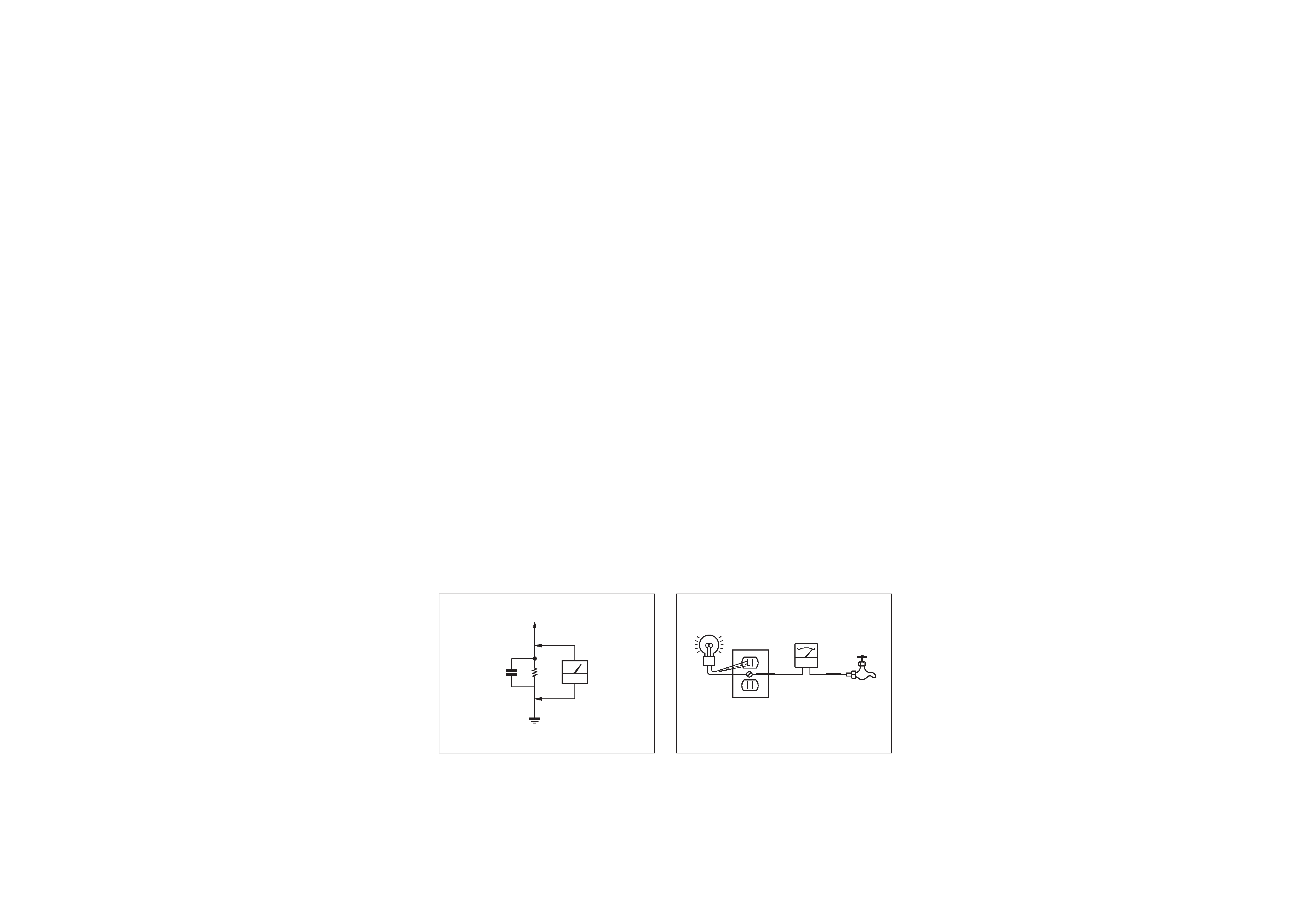
3. Measuring the voltage drop across a resistor by means of a
VOM or battery-operated AC voltmeter. The "limit" indica-
tion is 0.75V, so analog meters must have an accurate low-
voltage scale. The Simpson 250 and Sanwa SH-63Trd are
examples of a passive VOM that is suitable. NearIy all bat-
tery operated digital multimeters that have a 2V AC range
are suitable. (See Fig. A)
HOW TO FIND A GOOD EARTH GROUND
A cold-water pipe is guaranteed earth ground;the cover-plate re-
taining screw on most AC outlet boxes is also at earth ground. If
the retaining screw is to be used as your earth-ground, verify that it
is at ground by measuring the resistance between it and a cold-
water pipe with an ohmmeter. The reading should be zero ohms. If
a cold-water pipe is not accessible, connect a 60-l00 watts trouble
light (not a neon lamp) between the hot side of the receptacle and
the retaining screw. Try both slots, if necessary, to locate the hot
side of the line, the lamp should light at normal brilliance if the
screw is at ground potential. (See Fig. B)
0.15
µ F
1.5k
AC
voltmeter
(0.75V)
Earth Ground
To Exposed Metal
Parts on Set
Fig. A. Using an AC voltmeter to check AC leakage.
Trouble Light
AC Outlet Box
Ohmmeter
Cold-water Pipe
Fig. B. Checking for earth ground.

4
TABLE OF CONTENTS
Section
Title
Page
1.
GENERAL
Step 1 : Installing the projection TV .................................................................... 5
Step 2 : Hook up ................................................................................................... 6
Step 3 : Setting up the remote control .................................................................. 9
Step 4 : Setting up the projection TV automatically (AUTO SET UP) ............. 10
Changing the menu larguage .............................................................................. 12
Watching the TV ................................................................................................ 12
Watching tow programs at one time-PIP ............................................................ 13
Freezing the picture (FREEZE) .......................................................................... 14
Adjusting the picture (VIDEO) .......................................................................... 14
Adjusting the color temperature (TRINITONE) ................................................ 15
Selecting the video mode (VIDEO) ................................................................... 15
Adjusting the sound (AUDIO) ........................................................................... 15
Using audio effect (SURROUND) ..................................................................... 16
Selecting stereo or bilingual programs (MTS) ................................................... 16
Setting the speaker switch (SPEAKER) ............................................................. 16
Setting audio out (AUDIO OUT) ....................................................................... 17
Setting daylight saving time (DAYLIGHT SAVING) ....................................... 17
Setting the clock (CURRENT TIME SET) ........................................................ 17
Setting the timer to turn the projection TV on and off (ON/OFF TIMER) ........ 18
Customizing the channel names (CHANNEL CAPTION) ................................ 18
Blocking out a channel (CHANNEL BLOCK) .................................................. 19
Setting your favorite channels (FAVORITE CHANNEL) ................................. 19
Setting video labels (VIDEO LABEL) .............................................................. 19
Setting Caption Vision (CAPTION VISION) .................................................... 20
Operating video equipment ................................................................................ 20
Operating a cable box or DBS receiver .............................................................. 21
Troubleshooting .................................................................................................. 22
Index to parts and controls ................................................................................. 22
2.
DISASSEMBLY
2-1.
Rear Board Removal ............................................................................ 24
2-2.
Chassis Assy Removal .......................................................................... 24
2-3.
Service Position .................................................................................... 24
2-4-1.
HA Board Removal (KP-41T65) .......................................................... 25
2-4-2.
HA Board Removal (KP-46C65) ......................................................... 25
2-4-3.
HA Board Removal (KP-48S65/53S65/61S65) ................................... 25
2-5-1.
Beznet Assy Removal (KP-41T65) ...................................................... 26
2-5-2.
Beznet Assy Removal (KP-46C65/48S65/53S65) ............................... 26
2-5-3.
Screen Frame Assy Removal (KP-61S65) ........................................... 26
2-6-1.
Mirror Cover Assy Removal (KP-41T65) ............................................ 27
2-6-2.
Mirror Cover Assy Removal (KP-46C65/48S65/53S65/61S65) ................ 27
2-6-3.
Reflection Mirror Removal (KP-61S65) .............................................. 27
Section
Title
Page
2-7.
High-Voltage Cable Installation and Removal ..................................... 28
2-8-1.
Picture Tube Removal (KP-41T65) ...................................................... 28
2-8-2.
Picture Tube Removal (KP-46C65/48S65/53S65/61S65) ...................... 28
2-9-1.
Service stay Assy How to use and Carry Back Service stay Assy ....... 29
2-9-2.
Picture Tube Bracket Assy Removal (KP-41T65) ................................ 29
2-9-3.
Picture Tube BracketAssy Removal (KP-46C65/48S65/53S65/61S65) .............. 30
2-9-4.
Setting of Service stay Assy (KP-46C65/48S65/53S65) ........................ 31
2-9-5.
Install a Chassis Assy ........................................................................... 31
3.
SET-UP ADJUSTMENTS .............................................................. 32
4.
SAFETY RELATEDP ADJUSTMENTS ...................................... 45
5.
CIRCUIT ADJUSTMENTS ............................................................ 47
6.
DIAGRAMS
6-1. Block Diagram (1) ..................................................................................... 49
Block Diagram (2) ..................................................................................... 52
Block Diagram (3) ..................................................................................... 54
6-2. Frame Schematic Diagram ........................................................................ 55
6-3. Circuit Boards Location ............................................................................ 58
6-4. Printed Wiring Boards and Schematic Diagrams ...................................... 58
· A Board ................................................................................................... 59
· G Board ................................................................................................... 66
· PT Board ................................................................................................. 73
· CR, CG, CB Boards ................................................................................ 79
· Z Board ................................................................................................... 83
· HA Board ................................................................................................ 85
6-5. Semiconductors ......................................................................................... 87
7.
EXPLODED VIEWS
7-1. Cover (KP-41T65) ..................................................................................... 89
7-2. Cover (KP-46C65/48S65/53S65) .............................................................. 90
7-3. Cover (KP-61S65) ..................................................................................... 91
7-4. Chassis (KP-41T65) .................................................................................. 92
7-5. Chassis (KP-46C65/48S65/53S65/61S65) .................................................. 93
7-6. Picture Tube (KP-41T65) .............................................................................. 94
7-7. Picture Tube (KP-46C65/48S65/53S65/61S65) ............................................. 95
8.
ELECTRICAL PARTS LIST .......................................................... 96
(CAUTION)
SHORT CIRCUIT THE ANODE OF THE PICTURE TUBE AND
THE ANODE CAP TO THE METAL CHASSIS, CRT SHIELD, OR
CARBON PAINTED ON THE CRT, AFTER REMOVING THE AN-
ODE.
WARNING!!
AN ISOLATION TRANSFORMER SHOULD BE USED DURING
ANY SERVICE TO AVOID POSSIBLE SHOCK HAZARD, BE-
CAUSE OF LIVE CHASSIS.
THE CHASSIS OF THIS RECElVER IS DIRECTLY CONNECT-
ED TO THE AC POWER LINE.
SAFETY-RELATED COMPONENT WARNING!!
COMPONENTS IDENTIFIED BY SHADING AND MARK
! ON
THE SCHEMATIC DIAGRAMS, EXPLODED VIEWS AND IN THE
PARTS LIST ARE CRITICAL TO SAFE OPERATION. REPLACE
THESECOMPONENTS WITH SONY PARTS WHOSE PART NUM-
BERS APPEAR AS SHOWN IN THIS MANUAL OR IN SUPPLE-
MENTS PUBLISHED BY SONY. CIRCUIT ADJUSTMENTS THAT
ARE CRITICAL TO SAFEOPERATION ARE IDENTIFIED IN THIS
MANUAL. FOLLOW THESE PROCEDURES WHENEVER CRIT-
ICAL COMPONENTS ARE REPLACED OR IMPROPER OPER-
ATION IS SUSPECTED.
(ATTENTION)
APRES AVOIR DECONNECTE LE CAP DE L'ANODE,
COURTCIRCUITER L'ANODE DU TUBE CATHODIQUE ET CE-
LUI DE L'ANODE DU CAP AU CHASSIS METALLIQUE DE
L'APPAREIL, OU AU COUCHE DE CARBONE PEINTE SUR LE
TUBE CATHODIQUE OU AU BLINDAGE DU TUBE CATHOD-
IQUE.
ATTENTION!!
AFIN D'EVITER TOUT RISQUE DELECTROCUTION PROVE-
NANT D'UN CHÁSSIS SOUS TENSION, UN TRANSFORMATEUR
D'ISOLEMENT DOIT ETRE UTILISÉ LORS DE TOUT DEPAN-
NAGE.
LE CHÁSSIS DE CE RECEPTEUR EST DIRECTEMENT RAC-
CORDÉ Á L'ALIMENTATION SECTEUR.
ATTENTION AUX COMPOSANTS RELATIFS ÁLA
SÉCURITÉ!!
LES COMPOSANTS IDENTIFIÉS PAR UNE TRAME ET PAR UNE
MAPQUE
! SUR LES SCHÉMAS DE PRINCIPE, LES VUES EX-
PLOSÉES ET LES LISTES DE PIECES CONT D'UNEIMPORTANCE
CRITIQUE POUR LA SÉCURITÉ DU FONCTIONNEMENT. NE
LES REMPLACER QUE PAR DES COMPOSANTS SONY DONT
LE NUMÉRO DE PIÉCE EST INDIQUÉ DANS LE PRÉSENT
MANUEL OU DANS DES SUPPLÉMENTS PUBLIÉS PAR SONY.
LES RÉGLAGES DE CIRCUIT DONT L'IMPORTANCE EST CRI-
TIQUE POUR LA SÉCURITÉ DU FONCTIONNEMENT SONT
IDENTIFIES DANS LE PRÉSENT MANUEL. SUIVRE CES
PROCÉDURES LORS DE CHAQUE REMPLACEMENT DE COM-
POSANTS CRITIQUES, OU LORSQU'UN MAUVAIS FONCTION-
NEMENT EST SUSPECTÉ.
5
SECTION 1
GENERAL
The operating instructions mentioned here partial abstracts from the
Operating Instructions Manual. The page numbers of the Operating
Instruction Manual remain as in the manual.(part.no : 3-862-541-31)
4-EN
Welcome!
Thank you for purchasing the Sony Color Rear Video
Projection TV. Here are some of the features you will
enjoy with your projection TV:
· On-screen menus that let you set the picture quality,
sound, and other settings.
· Two tuner Picture-in-Picture (PIP) that allows you
to watch another TV channel, video or cable image
as a window picture.
· Surround system that simulates the sound quality of
a concert hall or movie theater.
· SAVA SPEAKER option of the AUDIO menu that
lets you take advantage of the Sony SAVA series
speaker system's surround sound and super woofer
mode when you connect it to the projection TV.
About this manual
The instructions in this manual are for models KP-
41T65, KP-46C65, KP-48S65, KP-53S65, and KP-61S65.
Before you start reading this manual, please check your
model number, located at the rear of the projection TV.
Model KP-53S65 is used for illustration purposes in this
manual. Any differences in operation are clearly
indicated in the text, for example "KP-61T65 only."
The differences in specifications are indicated in the
text.
Instructions in this manual are based on use of the
remote control. You can also use the controls on the
projection TV if they have the same name as those on
the remote control.
Precautions
This projection TV operates on extremely high voltage.
To prevent fire or electric shock, please follow the
precautions below.
Safety
· Operate the projection TV only on 120 V AC.
· One blade of the plug is wider than the other for safety
purposes and will fit into the power outlet only one
way. If you are unable to insert the plug fully into the
outlet, contact your dealer.
· Should any liquid or solid object fall into the cabinet,
unplug the projection TV and have it checked by
qualified personnel before operating it further.
· Unplug the projection TV from the wall outlet if you
are not going to use it for several days or more. To
disconnect the cord, pull it out by the plug. Never
pull the cord itself.
For details concerning safety precautions, see the supplied
leaflet "IMPORTANT SAFEGUARDS."
Note on cleaning
Clean the cabinet of the projection TV with a dry soft
cloth. To remove dust from the screen, wipe it gently
with a soft cloth using vertical strokes only. Stubborn
stains may be removed with a cloth slightly dampened
with solution of mild soap and warm water. Never use
strong solvents such as thinner or benzine for cleaning.
If the picture becomes dark after using the projection TV
for a long period of time, it may be necessary to clean the
inside of the projection TV. Consult qualified service
personnel.
Installing
· To prevent internal heat build-up, do not block the
ventilation openings.
· Do not install the projection TV in a hot or humid
place, or in a place subject to excessive dust or
mechanical vibration.
· Avoid operating the projection TV at temperatures
below 5
°C (41°F).
· If the projection TV is transported directly from a cold
to a warm location, or if the room temperature has
changed suddenly, the picture may be blurred or show
poor color. This is because moisture has condensed on
the mirror or lenses inside. If this happens, let the
moisture evaporate before using the projection TV.
· To obtain the best picture, do not expose the screen to
direct illumination or direct sunlight. It is
recommended to use spot lighting directed down from
the ceiling or to cover the windows that face the screen
with opaque drapery. It is desirable to install the
projection TV in a room where the floor and walls are
not of reflecting material. If necessary, cover them
with dark carpeting or wall paper.
Getting Started
5-EN
EN
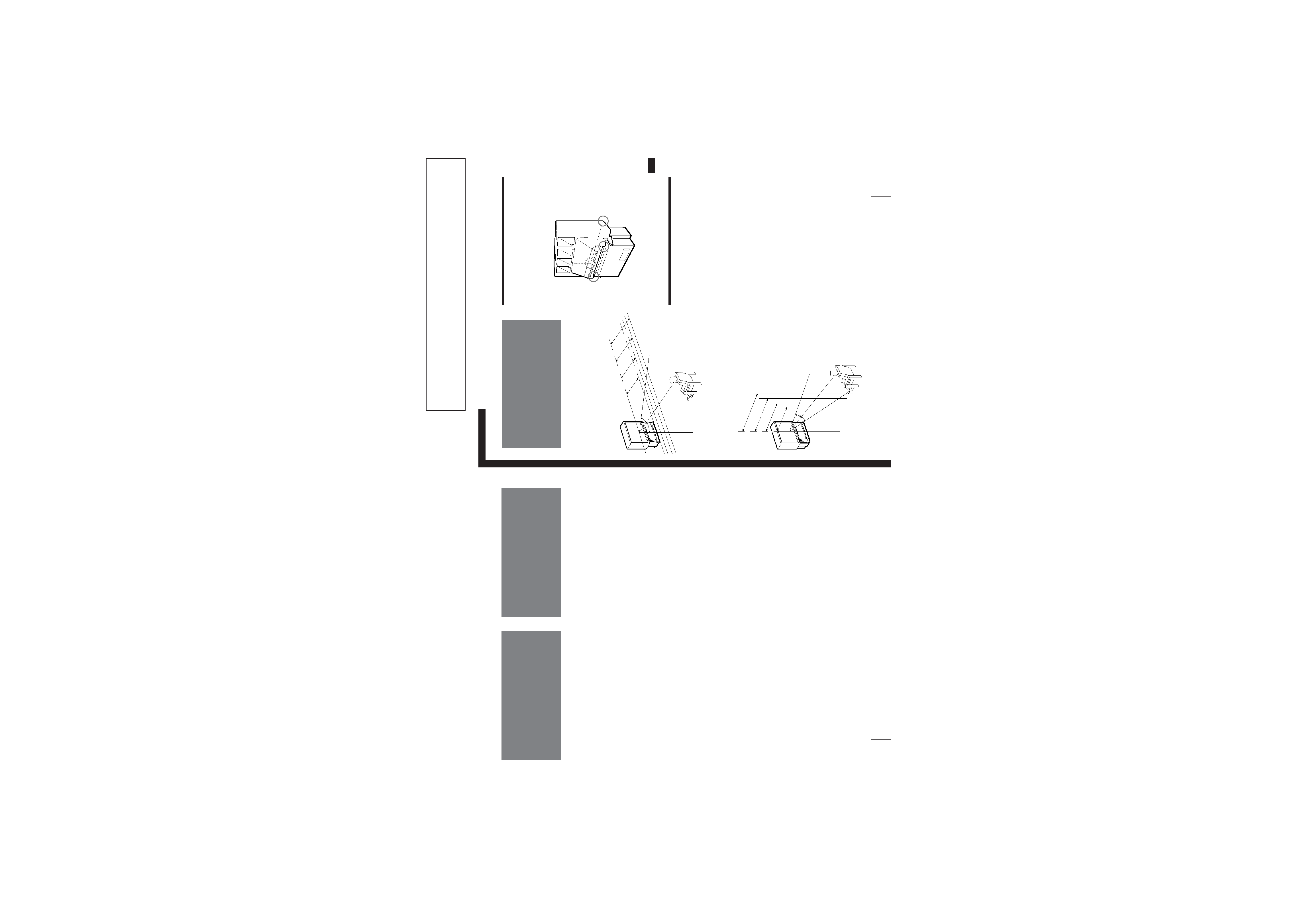
Carrying your projection TV
p
KP-41T65/46C65/48S65/53S65 only
Be sure to grasp the areas indicated when carrying the
projection TV, and to use more than two people.
p
KP-61S65 only
Carry your projection TV by the casters.
Preparing for your projection TV
Before you use your projection TV, adjust convergence.
For the procedure, see "Step 4: Setting up the projection
TV automatically (AUTO SET UP)" on page 14.
Getting Started
Step 1: Installing
the projection TV
For the best picture quality, install the projection TV
within the areas shown below.
Optimum viewing area (Horizontal)
Optimum viewing area (Vertical)
(Rear of projection TV)
60¡
min.
2.1m
(approx.
7 ft.)
53"
min.
1.8m
(approx.
6 ft.)
46",
48"
min.
1.5m
(approx.
5 ft.)
41"
min.
2.4m
(approx.
8 ft.)
61"
60°
60°
min.
2.1m
(approx.
7 ft.)
53"
min.
1.8m
(approx.
6 ft.)
46",
48"
min.
1.5m
(5 ft.)
41"
min.
1.5m
(5 ft.)
41"
min.
2.4m
(approx.
8 ft.)
61"
20°
20°