
COLOR REAR VIDEO PROJECTION
SERVICE MANUAL
AX-1X CHASSIS
MODEL NAME
REMOTE COMMANDER
DESTINATION
CHASSIS NO.
9-965-968-06
KP-46WT520
RM-Y916
US/CND/MX
SCC-M37B-A
KP-51WS520
RM-Y916
US/CND/MX
SCC-M37C-A
KP-57WS520
RM-Y916
US/CND/MX
SCC-M37A-A
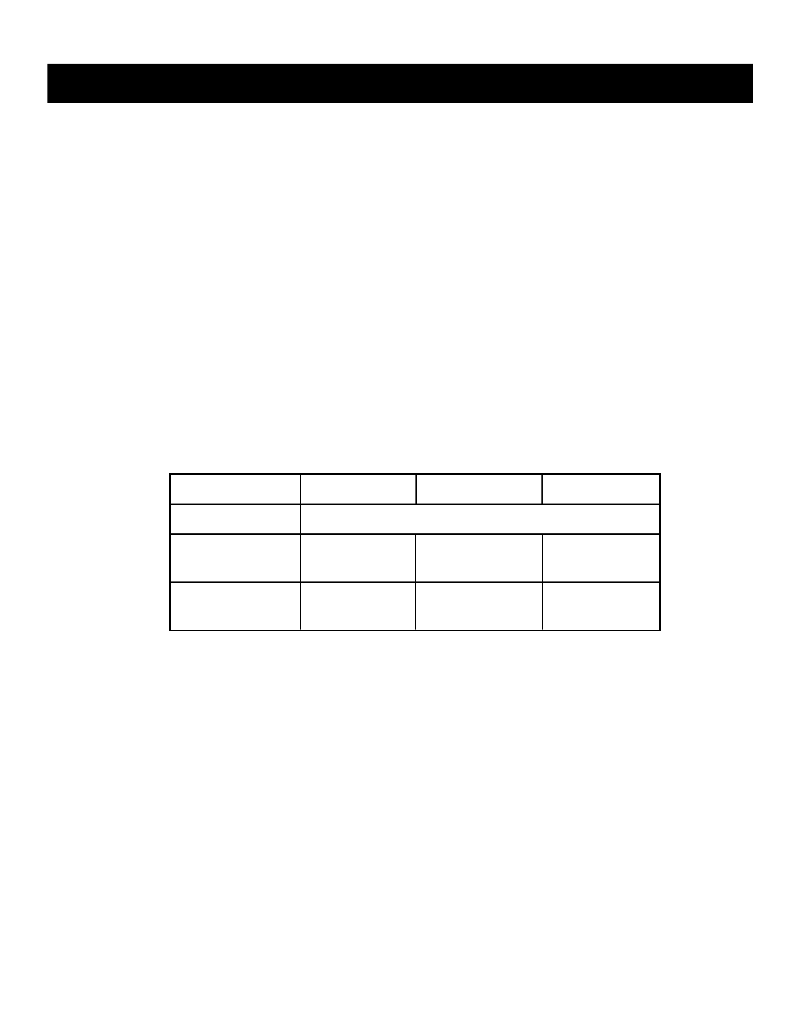
HISTORY INFORMATION FOR THE FOLLOWING MANUAL:
ORIGINAL MANUAL ISSUE DATE: 7/2004
:UPDATED ITEM
REVISION DATE
SUBJECT
7/2004
No revisions or updates are applicable at this time.
10/2004
Corrected 1-9. Speaker Grille, HA1 Board, and HB2 Board Removal (KP-46WT520 Only)
to show correct location of HB2 Board. Replaced Page 14 with Page 14
Removed Note from section 2-12-1. Setup For Adjustment. Note is intended for use by the factory
during production, and should not be performed by service technicians. Replaced Page 50 with Page 50
12/2004
Corrected PN for AC Power Cord for KP-51WS520/57WS520 Models.
Replaced Page 104 with Page 104
12/2004
Corrected PN for Resistor Bridge on A Board Replaced Page 127 with Page 127
2/2005
Updated Table of Contents (Replaced Page 3 with Page 3)
Added Caution statement (Replaced Page 5 with Page 5)
BH Board introduced due to design change.
Added BH Board Removal to Disassembly section (Replaced Page 12 with Page 12)
Added BH Board Schematics, PWBs, Exploded View, and Electrical Parts List
(Added Pages 93-A through 93-C, Replaced Pages 148-150 with Pages 148-157)
Corrected PN for Bottom Cabinet (46) Assy, Corrected/removed items included in Speaker Grill Assembies
(Replaced Page 102 & 103 with Page 102 & 103)
Added BH Board and A Board (Replaced Page 104 with Page 104)
New CRT Coupler Assemblies & Shades introduced for KP-46WT520/51WS520
Affects SNs 8,500,001 and up (Replaced Page 105 with Page 105)
Added A Board differences to Electrical Parts List (Replaced Page 111 and 118 with 111 and 118)
8/2005
Corrected position of CRT Couplers and Shades (Replaced Page 105 with 105)
COLOR REAR VIDEO PROJECTION
SERVICE MANUAL
AX-1X CHASSIS
MODEL NAME
REMOTE COMMANDER
DESTINATION
CHASSIS NO.
9-965-968-06
KP-46WT520
RM-Y916
US/CND/MX
SCC-M37B-A
KP-51WS520
RM-Y916
US/CND/MX
SCC-M37C-A
KP-57WS520
RM-Y916
US/CND/MX
SCC-M37A-A
Self Diagnosis
Supported model
KP-51WS520
RM-Y916

KP-46WT520/51WS520/57WS520
KP-46WT520/51WS520/57WS520
3
SECTION 4: CIRCUIT ADJUSTMENTS.............................................. 60
4-1. P & P Sub Contrast Adjustment (Video) (SCON) ................. 60
4-2. P & P Sub Contrast Adjustment (RF) (SCON) ..................... 60
4-3. P & P Sub-Hue and Sub-Color Adjustment Video
(SHUE, SCOL) ..................................................................... 60
4-4. P & P Sub-Hue and Sub-Color Adjustment (RF)
(SHUE, SCOL) ..................................................................... 60
4-5. Blue Offset Adjustment ....................................................... 61
SECTION 5: DIAGRAMS..................................................................... 62
5-1. Circuit Boards Location ........................................................ 62
5-2. Printed Wiring Boards and
Schematic Diagrams Information ......................................... 62
5-3. Block Diagrams .................................................................... 64
Signal Flow Block Diagram .................................................. 64
Power Block Diagram........................................................... 65
Audio Signal Path Block Diagram ........................................ 66
Video Path Block Diagram ................................................... 67
SYNC/OSD Path Block Diagram.......................................... 68
5-4. Schematics and Supporting Information ............................. 69
CR Board Schematic Diagram ............................................ 69
CB Board Schematic Diagram ............................................ 70
CG Board Schematic Diagram ............................................ 71
VM Board Schematic Diagram ............................................ 74
A Board Schematic Diagram (1 of 6).................................... 75
A Board Schematic Diagram (2 of 6).................................... 76
A Board Schematic Diagram (3 of 6).................................... 77
A Board Schematic Diagram (4 of 6).................................... 78
A Board Schematic Diagram (5 of 6).................................... 79
A Board Schematic Diagram (6 of 6).................................... 80
D Board Schematic Diagram (1 of 2) ................................... 85
D Board Schematic Diagram (2 of 2) ................................... 86
BM Board Schematic Diagram (1 of 3) ................................ 90
BM Board Schematic Diagram (2 of 3) ................................ 91
BM Board Schematic Diagram (3 of 3) ................................ 92
BH Board Schematic Diagram (1 of 2).............................. 93-A
BH Board Schematic Diagram (2 of 2)..............................93-B
G Board Schematic Diagram ............................................... 94
HA1 Board Schematic Diagram .......................................... 97
P Board Schematic Diagram................................................ 98
SR Board Schematic Diagram ............................................ 99
HB1 Board Schematic Diagram
(KP-51WS520/57WS520 Only) .............................. 99
HB2 Board Schematic Diagram (KP-46WT520 Only).......... 99
5-5. Semiconductors ................................................................. 101
SECTION 6: EXPLODED VIEWS ...................................................... 102
6-1. Cover (KP-46WT520 Only) ................................................ 102
6-2. Cover (KP-51WS520/57WS520 Only) ............................... 103
6-3. Chassis .............................................................................. 104
6-4. Picture Tube ....................................................................... 105
SECTION 7: ELECTRICAL PARTS LIST.......................................... 106
Specifications ................................................................................. 4
Warnings and Cautions .................................................................. 5
Safety Check-Out ........................................................................... 6
Self-Diagnostic Function................................................................. 7
SECTION 1: DISASSEMBLY............................................................... 10
1-1. Rear Board Removal............................................................ 10
1-2. Chassis Assembly Removal................................................. 10
1-3. Service Position ....................................................................11
1-4. Terminal Board and P Board Removal..................................11
1-5. BM Board or BH Board Removal ......................................... 12
1-6. A Board, D Board, and G Board Removal............................ 12
1-7. High-Voltage Cable Installation and Removal...................... 13
1-8. Picture Tube Removal.......................................................... 13
1-9. Speaker Grille, HA1 Board, and HB2 Board Removal
(KP-46WT520 Only)............................................................. 14
1-10.Speaker Grille, HA1 Board, and HB1 Board Removal
(KP-51WS520/57WS520 Only)............................................ 14
1-11. Beznet Assembly Removal .................................................. 15
1-11-1. Screen Tape Method................................................ 15
1-12.SR Board Removal .............................................................. 16
Wire Dressing ............................................................................... 17
SECTION 2: SET-UP ADJUSTMENTS................................................ 31
2-1. Screen Voltage Adjustment (G2) (Coarse Adjustment) ........ 31
2-2. Screen (G2) Adjustment (Fine Adjustment).......................... 31
2-3. Deflection Yoke Tilt Adjustment ............................................ 31
2-4. Focus Lens Adjustment........................................................ 32
2-5. Focus VR Adjustment........................................................... 32
2-6. Centering Magnet Adjustment.............................................. 33
2-7. 2-Pole Magnet Adjustment .................................................. 33
2-8. 4-Pole Magnet Adjustment ................................................... 33
2-9. Defocus Adjustment (Blue)................................................... 33
2-10.Electrical Adjustments by Remote Commander................... 34
2-10-1. Method of Entering the Service Adjustment Mode .. 34
2-10-2. Memory Write Confirmation Method ........................ 34
2-10-3. Adjusting Buttons and Indicator ............................... 34
2-11. Adjustable Service Data Lists .............................................. 35
2-11-1. ID Map Table............................................................ 49
2-12.Registration Adjustment (PJE Mode Only)........................... 50
2-12-1. Setup for Adjustment ............................................... 50
2-12-2. Main Deflection Adjustment ..................................... 50
2-12-3. Operation Method for Projector Engine Mode ......... 51
2-13.PJE Adjustment (Sub Deflection Adjustment) ...................... 52
2-13-1. Adjustment for NTSC Full Mode .............................. 53
2-13-2. Copying All Registration Data to Other Modes ........ 55
2-14.Auto Registration Offsets ..................................................... 55
2-15.Auto Registration Error Codes ............................................. 56
2-16.Auto Registration Diagnostics .............................................. 57
SECTION 3: SAFETY-RELATED ADJUSTMENTS............................. 58
D BOARD ..................................................................................... 58
3-1. HV Regulation Circuit Check and Adjustment...................... 58
3-2. HV Hold Down Circuit Operation Check .............................. 58
G BOARD ..................................................................................... 59
3-3. +B Max Voltage Confirmation .............................................. 59
3-4. +B OVP Confirmation........................................................... 59
SECTION TITLE
PAGE
SECTION TITLE
PAGE
TABLE OF CONTENTS
KP-46WT520/51WS520/57WS520
KP-46WT520/51WS520/57WS520
4
120V AC, 60Hz
235W
Under 1 W
HDMI IN
Video
1080i, 720p, 480p, 480i
Audio
Two channel linear PCM 32, 44.1, and 48 kHz, 16, 20, and 24 bit
Video (IN)
4 total (1 on front panel)
1Vp-p, 75ohms unbalanced, sync negative
S Video (IN)
3 total (1 on front panel)
Y: 1Vp-p, 75ohms unbalanced, sync negative
C: 0.286Vp-p (Burst signal), 75ohms
Projection System
3 picture tubes, 3 lenses, horizontal in-line system
Picture Tube
7-inch high-brightness monochrome tubes (6.3 raster size),
with optical coupling and liquid cooling system.
Projection Lenses
High performance, large diameter hybrid lens F1.1
Antenna
75 ohm external terminal for VHF/UHF
Television System
NTSC, American TV Standard
Channel Coverage
VHF: 2-13/UHF: 14-69/CATV: 1-125
SPECIFICATIONS
Design and specifications are subject to change without notice.
Power Requirements
Power Consumption (W)
In Use (Max)
In Standby
Inputs/Outputs
Screen Size (measured diagonally)
46 inches (KP-46WT520)
51 inches (KP-51WS520)
57 inches (KP-57WS520)
Supplied Accessories
Remote Control RM-Y916
Batteries (2) size AA (R6)
Optional Accessories
A/V Cable (VMC-810/820/830 HG)
Audio Cable (RKC-515HG)
Component Video Cable (VMC-10/30 HG)
Control S Cable (RK-G69HG)
TV Stand SU-46WT11 (For KP-46WT520 Only)
Audio (IN)
7 total (1 on front panel)
500 mVrms (100% modulation)
Impedance:47 kilohm
Component Video Input
2 ( Y,PB,PR)
Y: 1.0 Vp-p, 75 ohms unbalanced, sync negative;
PB: 0.7 Vp-p, 75 ohms;
PR: 0.7 Vp-p, 75 ohms
Control S (IN/OUT)
1 total
Variable/Fixed Audio (OUT)
More than 408 m Vrms at the maximum volume setting
(Variable)
More than 408 m Vrms (Fixed) Impedance (output):2 kilohms
KP-46WT520
KP-46WT520
KP-51WS520
KP-51WS520
KP-57WS520
KP-57WS520
20W x 2
1086 x 1017 x 609 mm
1194 x 1280 x 666 mm
1326 x 1377 x 692 mm
423/4 x 40 x 24 in
47 x 501/2 x 261/4 in
521/4 x 541/4 x 271/4 in
61.3 kg
77.2 kg
88 kg
135 lbs
170 lbs
194 lbs
Speaker Output (W)
Dimensions (W x H x D)
mm
in
Mass
kg
lbs

KP-46WT520/51WS520/57WS520
KP-46WT520/51WS520/57WS520
5
WARNINGS AND CAUTIONS
CAUTION
These servicing instructions are for use by qualified service personnel only. To reduce the risk of electric shock, do not perform any
servicing other than that contained in the operating instructions unless you are qualified to do so.
WARNING!!
An isolation transformer should be used during any service to avoid possible shock hazard, because of live chassis. The chassis of
this receiver is directly connected to the ac power line.
! SAFETY-RELATED COMPONENT WARNING!!
Components identified by shading and ! mark on the schematic diagrams, exploded views, and in the parts list are critical for safe
operation. Replace these components with Sony parts whose part numbers appear as shown in this manual or in supplements
published by Sony. Circuit adjustments that are critical for safe operation are identified in this manual. Follow these procedures
whenever critical components are replaced or improper operation is suspected.
ATTENTION!!
Ces instructions de service sont à l'usage du personnel de service qualifié seulement. Pour prévenir le risque de choc électrique, ne
pas faire l'entretien autre que celui contenu dans le Mode d'emploi à moins que vous soyez qualifié faire ainsi.
Afin d'eviter tout risque d'electrocution provenant d'un chássis sous tension, un transformateur d'isolement doit etre utilisé lors de tout
dépannage. Le chássis de ce récepteur est directement raccordé à l'alimentation du secteur.
! ATTENTION AUX COMPOSANTS RELATIFS A LA SECURITE!!
Les composants identifies par une trame et par une marque ! sur les schemas de principe, les vues explosees et les listes de pieces
sont d'une importance critique pour la securite du fonctionnement. Ne les remplacer que par des composants Sony dont le numero
de piece est indique dans le present manuel ou dans des supplements publies par Sony. Les reglages de circuit dont l'importance
est critique pour la securite du fonctionnement sont identifies dans le present manuel. Suivre ces procedures lors de chaque
remplacement de composants critiques, ou lorsqu'un mauvais fonctionnement suspecte.