CHASSIS
SERVICE MANUAL
MODEL
COMMANDER
DEST. CHASSIS NO.
MODEL
COMMANDER
DEST. CHASSIS NO.
Please file according to model size. .......
RA-3A
KP-43T75A
RM-Y906 Argentine
SCC-P24A-A
KP-53SV75A RM-Y906 Argentine SCC-P24B-A
43
COLOR REAR VIDEO PROJECTOR
53
KP-43T75A
KP-53SV75A
RM-Y906
TV
2
5
8
0
1
4
7
3
6
9
ENTER
JUMP
GUIDE
INDEX
RESET
MENU
CODE SET
VOL
CH
POWER
MUTING
FREEZE
AUDIO
ANT
TV/VIDEO
DISPLAY
MTS/SAP
CC
PICTURE
MODE
POSITION
ACTIVE
SWAP
PIP
TV/VTR
SYSTEM
OFF
DVD/VTR SAT/CABLE
TV
DVD/
VTR
SAT/
CABLE
FUNCTION
SLEEP
m
N
M
x
z
X
TV

2
KP-43T75A/53SV75A
RM-Y906
RM-Y906
SPECIFICATIONS
Projection system
3 picture tubes, 3 lenses, horizontal in-line system
Picture tube
7-inch high-brightness monochrome tubes (6.3 raster size),
with optical coupling and liquid cooling system
Projection lenses
High performance, large diameter hybrid lens F1.05
Television system
PAL - N, PAL - M, NTSC
Channel coverage
VHF: 213/UHF: 14 69/CATV: 1 125
Antenna
75 ohm external terminal for VHF/UHF
Screen size (measured diagonally)
43 inches (KP-43T75A)
53 inches (KP-53SV75A)
Inputs/outputs
VIDEO 1 IN
VIDEO 2 INPUT
S VIDEO IN (4-pin mini DIN):
Y: 1 Vp-p, 75-ohms unbalanced, sync negative
C: 0.286 Vp-p (Burst signal), 75 ohms
VIDEO (phono jack): 1 Vp-p, 75-ohms unbalanced,
sync negative
AUDIO (phono jacks): 500 mVrms (100% modulation),
Impedance: 47 kilohms
VIDEO 3 IN
S VIDEO IN (4-pin mini DIN):
Y: 1 Vp-p, 75-ohms unbalanced, sync negative
C: 0.286 Vp-p (Burst signal), 75 ohms
VIDEO (phono jack): 1 Vp-p, 75-ohms unbalanced,
sync negative
Y: 1 Vp-p, 75 ohms, sync negative
PB: 0.7 Vp-p, 75 ohms
PR: 0.7 Vp-p, 75 ohms
AUDIO (phono jacks): 500 mVrms (100% modulation),
Impedance: 47 kilohms
MONITOR OUT
VIDEO (phono jack): 1 Vp-p, 75-ohms unbalanced,
sync negative
AUDIO (phono jacks): 500 mVrms (100% modulation),
Impedance: 470 ohms
AUDIO (VAR/FIX) OUT (phono jacks): 500 mVrms
(100% modulation), Impedance: 470 ohms
CONTROL S OUT: minijack
Speaker
66 mm (2 5/8")
× 2, 160 mm (6 3/8") × 2 (KP-53SV75A)
100 mm (4")
× 2 (KP-43T75A)
Speaker output
17W
× 2
Power requirement
110-220 V AC, 50/60 Hz
Power consumption
In use (Max.): 160 W
In standby: 1 W
Dimensions (W/H/D)
965
× 1,058 × 510 mm (38 × 41 5/8 × 20 1/8 inches)
(KP-43T75A)
1,216
× 1,417 × 632 mm (47 7/8 × 55 3/4 × 24 7/8 inches)
(KP-53SV75A)
Mass
65 kg (143 lbs 5 oz) (KP-43T75A)
77 kg (169 lbs 12 oz) (KP-53SV75A)
Supplied accessories
Remote control RM-Y906 (1)
Batteries (2) size AA (R6)
Optional accessories
Connecting cables
RK-G34, RK-74A, RK-G69HG, VMC-10HG,
VMC-720M, VMC-810S/820S, YC-15V/30V
U/V mixer EAC-66
Design and specifications are subject to change without notice.
3
KP-43T75A/53SV75A
RM-Y906
RM-Y906
SELF DIAGNOSIS FUNCTION
* : 000 the range of values for number of operations is 000-255. For 256 or higher there is
no count up and the number remains at 255.
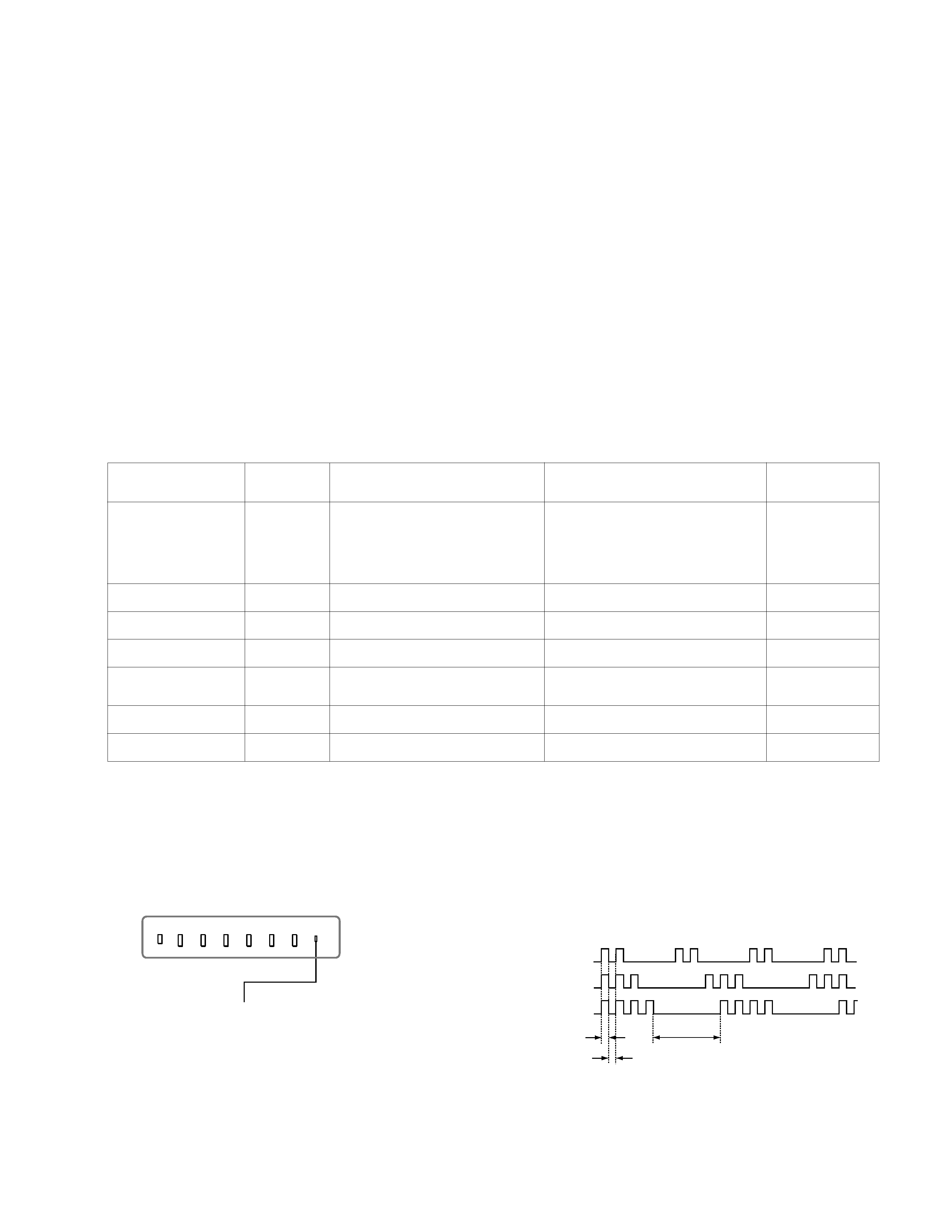
3.
Blinking count display of TIMER/STAVDBY indicator
< FRONT PANEL >
TIMER/STANDBY indicator
Lamp OFF :
3.0 seconds
Lamp ON : 0.3 seconds
Lamp OFF : 0.3 seconds
Release of TIMER/STANDBY indicator blinking.
·
The TIMER/STANDBY indicator blinking display is released by turning OFF the power switch
on the TV main unit or removing the plug from the power.
* One blink is not used for self-diagnosis.
·EXAMPLE
<Diagnosis Items>
<Number of Blinks>
· +B overcurrent
2 times
· +B overvoltage
3 times
· Vertical deflection stop
4 times
TV/VIDEO
FLASH FOCUS
VOLUME
POWER TIMER/STAND BY
+
CHANNEL
+
1.
Summary of Self-Diagnosis Function
·
This device includes a self-diagnosis function.
·
In case of abnormalities, the TIMER/STANDBY indicator automatically blinks. It is possible to predict the abnormality location
by the number of blinks. The Instruction Manual describes blinking of the TIMER/STANDBY indicator.
·
If the symptom is not reproduced sometimes in case of a malfunction, there is recording of whether a malfunction was generated
or not. Operate the remote command to confirm the matter on the screen and to predict the location of the abnormality.
2.
Diagnosis Items and Prediction of Malfunction Location
·
When a malfunction occurs the TIMER/STANDBY indicator only blinks for one of the following diagnosis items. In case of two
or more malfunctions, the item which first occurred blinks. If the malfunctions occurred simultaneously, the item with the lower
blink count blinks first.
·
The screen display displays the results regarding all the diagnosis items listed below. The display " 0 " means that no malfunc-
tions occurred.
m
e
t
i
s
i
s
o
n
g
a
i
D
Y
B
D
N
A
T
S
/
R
E
M
I
T
r
e
t
a
c
i
d
n
I
s
k
n
i
l
b
f
o
r
e
b
m
u
N
n
o
i
t
c
n
u
f
l
a
m
d
e
s
o
p
p
u
Sn
o
i
t
i
d
n
o
C
s
i
s
o
n
g
a
i
d
-
f
l
e
S
,
y
a
l
p
s
i
d
n
e
e
r
c
s
s
t
l
u
s
e
R
:
m
e
t
i
s
i
s
o
n
g
a
i
D
N
O
t
o
n
r
e
w
o
P
·0
]
m
e
t
s
y
S
y
l
p
p
u
S
r
e
w
o
P
y
b
d
n
a
t
S
[
.
n
e
p
o
1
0
6
F
.
n
e
p
o
7
0
6
R
t
i
u
c
r
i
c
t
r
o
h
s
1
0
6
Q
]
m
e
t
s
y
S
y
l
p
p
u
S
r
e
w
o
P
n
i
a
M
[
.
n
e
k
o
r
b
e
r
a
2
1
6
R
d
n
a
1
0
6
C
I
t
i
u
c
r
i
c
-
t
r
o
h
s
1
0
6
R
D
V
.
r
e
w
o
p
e
h
t
n
o
n
r
u
t
t
o
n
n
a
C
.
k
n
il
b
t
'
n
s
e
o
d
D
E
L
n
o
i
t
c
e
t
e
d
P
C
O
B
+s
e
m
i
t
2.
t
i
u
c
r
i
c
h
c
a
e
n
i
m
e
t
s
y
s
y
l
p
p
u
s
r
e
w
o
p
f
o
t
i
u
c
r
i
c
t
r
o
h
S
e
d
o
m
y
b
d
n
a
t
s
e
h
t
o
t
s
e
o
G
e
n
il
B
+
f
o
t
i
u
c
r
i
c
t
r
o
h
S
0
0
0
P
C
O
B
+
:
2
n
o
i
t
c
e
t
e
d
P
V
O
B
+s
e
m
i
t
3
.
n
e
p
o
8
7
n
i
p
3
0
6
T
.
n
e
p
o
2
7
6
R
e
d
o
m
y
b
d
n
a
t
s
e
h
t
o
t
s
e
o
G
t
i
u
c
r
i
c
y
l
p
p
u
s
r
e
w
o
p
f
o
n
o
i
t
c
n
u
f
l
a
M
0
0
0
P
V
O
B
+
:
3
p
o
t
s
n
o
i
t
c
e
l
f
e
d
l
a
c
i
t
r
e
Vs
e
m
i
t
4
.
n
e
k
o
r
b
s
i
)
t
u
o
V
(
9
0
5
1
C
I
.
n
e
k
o
r
b
s
i
)
r
e
f
f
u
B
e
s
l
u
P
V
(
5
0
5
1
Q
o
e
d
i
v
n
e
h
t
d
n
a
A
,
y
ll
a
t
n
o
z
i
r
o
h
e
n
il
e
n
o
o
t
s
e
o
g
r
e
t
s
a
R
.
d
e
t
u
m
s
i
l
a
n
g
i
s
0
0
0
p
o
t
S
V
:
4
n
o
i
t
c
e
t
e
d
y
t
il
a
m
r
o
n
b
a
t
u
o
o
e
d
i
Vs
e
m
i
t
5
d
r
a
o
b
C
n
i
s
r
e
h
t
o
d
n
a
1
6
7
,
2
3
7
,
5
0
7
Q
,
t
u
o
o
e
d
i
V
.
t
i
u
c
r
i
c
)
d
r
a
o
b
A
(
0
2
2
,
9
1
2
,
8
1
2
Q
,
s
d
n
o
c
e
s
0
3
.
x
o
r
p
p
a
s
k
n
il
b
D
E
L
Y
B
D
N
A
T
S
/
R
E
M
I
T
.
s
i
s
o
n
g
a
i
d
f
l
e
s
e
h
t
r
o
f
s
k
n
il
b
n
e
h
t
d
n
a
0
0
0
B
K
A
:
5
p
o
t
s
n
o
i
t
c
e
l
f
e
d
l
a
t
n
o
z
i
r
o
Hs
e
m
i
t
6
.
n
e
p
o
6
1
5
,
5
1
5
C
.
n
e
k
o
r
b
s
i
)
e
l
g
n
u
J
C
Y
(
6
0
2
C
I
.
r
a
e
p
p
a
t
'
n
s
e
o
d
r
e
t
s
a
R0
0
0
p
o
t
S
H
:
6
n
o
i
t
c
e
t
e
d
y
t
il
a
m
r
o
n
b
a
o
i
d
u
As
e
m
i
t
8
.
n
e
k
o
r
b
s
i
)
.
p
m
a
o
i
d
u
A
(
6
0
4
C
I
.
n
e
p
o
2
0
4
,
1
0
4
S
P
.
t
u
o
t
o
n
s
i
d
n
u
o
s
e
h
T
e
d
o
m
y
b
d
n
a
t
s
e
h
t
o
t
s
e
o
G
0
0
0
o
i
d
u
A
:
8
4
KP-43T75A/53SV75A
RM-Y906
RM-Y906
4.
Self-diagnosis screen displays
·
In cases of malfunctions where it is not possible to determine the symptom such as when the power goes off occasionally or when
the screen disappears occasionally, there is a screen display on whether the malfunction occurred or not in the past (and whether
the detection circuit operated or not) in order to allow confirmation.
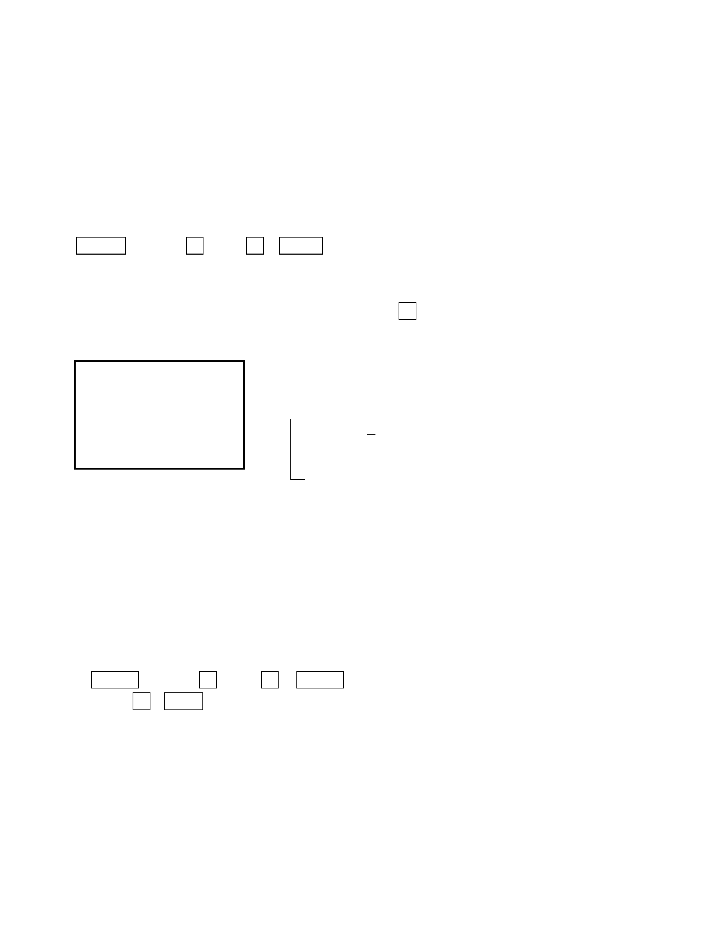
<Screen Display Method>
·
Quickly press the remote command button in the following order from the standby state.
Self Check
2 : +B OCP
000
2 : +B OCP
000
3 : +B OVP
000
4 : V Stop
000
5 : AKB
000
6 : H Stop
000
7 : HV
000
8 : Audio
000
101 : WDT
000
000 the range of values for number of
operations is 000-255.
For 256 or higher there is no count up
and the number remains at 255.
Diagnosis
Results
÷
Self-diagnosis screen display
5.
Self-Diagnosis Screen Display
·
The results display is not automatically cleared. In case of repairs and after repairs, check the self-diagnosis screen and be sure
to return the results display to " 0 ".
·
If the results display is not returned to " 0 " it will not be possible to judge a new malfunction after completing repairs.
<Method of Clearing Results Display>
<Method of Ending Self Diagnosis Screen>
·
When ending the self-diagnosis screen completely, turn the power switch OFF on the remote commander or the main unit.
Be aware that this differs from the method of
entering the service mode (volume + ).
DISPLAY b Channel
5 b VOL
b
POWER
1. Power off (Set to the standby mode)
2. DISPLAY b Channel
5
b
VOL
+
b
POWER
(Service Mode)
3. Channel
8 b ENTER (Test reset = Factory preset condition)
5
KP-43T75A/53SV75A
RM-Y906
RM-Y906
6. Self-diagnosis function operation
OCP
Low B and +B line detect DET SHORT, and shut-down POWER ON RELAY.
Reset by turning power on/off.
In case of +B is loaded approx. 1.3A or more, microcomputer detects it via IC651.
OVP
In case of +B becomes approx. 150V or more, POWER ON RELAY shuts down and microcomputer detects it via IC651.
Reset by turning power on/off just the same as OCP.
V Stop
In case of microcomputer detects 2 seconds or more interval of V Pulse, Reference Pulse turns off by turning off the picture
signal in YC Jungle IC (IC206).
After the picture signal turns off, V Pulse is regenerated 2 seconds or more, the picture signal turns on.
AKB
IK detection. Makes LED blinking in case of microcomputer doesn't detect IK returns of IC206 CXA2135 30 seconds or more.
H Stop
In case of HV becomes 33kV or more, IC502 detects it and shut-down H Drive Pulse.
Microcomputer receives H Stop data from IC206 and makes LED blinking.
Audio
In case of DC component overlaps the output of Audio Amp., microcomputer detects it and makes LED blinking.
Microcomputer forces to shut down the power.
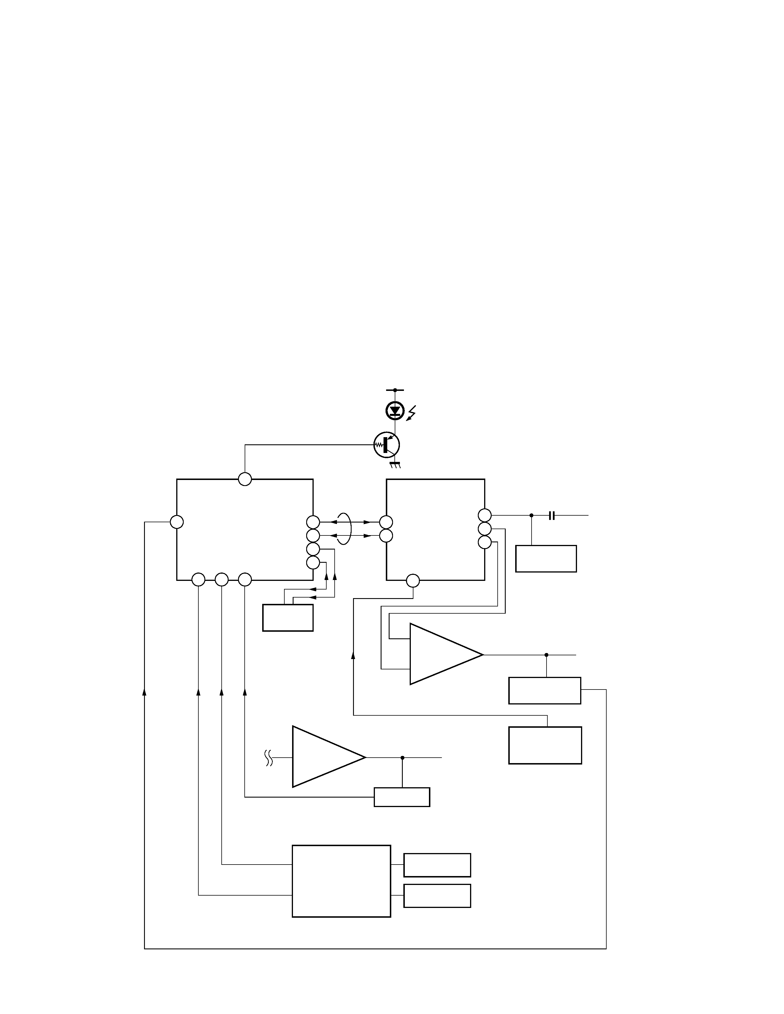
Self-diagnosis block diagram
55
8
20
21
22
49
47
50
34
21
14
13
18
5. AKB
5. AKB
3. OVP
2. OCP
4. V.STOP (V Pulse)
Audio
IC002
µProcessor
IC206
CXA2135
YCJ
Q007
D1201
TIMER/STANDBY
IC004
EEPROM
IC502
HV Detector
Q1505
V Pulse Buffer
IC651
OVP Buffer
OCP Buffer
C Board
DC Detect
IC1509
V Drive
IC406
Audio AMP
6. H STOP
6. HV STOP
BUS
35
48
OVP DETECT
OCP DETECT