CHASSIS
RA-2A
SERVICE MANUAL
MODEL
COMMANDER
DEST. CHASSIS NO.
KP-41T65K
RM-Y149A
Korea SCC-N94A-A
KP-41T65T
RM-Y136A
Taiwan SCC-N95A-A
KP-53S65T
RM-Y136A
Taiwan SCC-N95B-A
MODEL
COMMANDER
DEST. CHASSIS NO.
MICROFILM
41
48
Please file according to model size. .......
Color Rear Video Projector
53
KP-48V75K
RM-Y901K
Korea SCC-N94B-A
KP-53V75K
RM-Y901K
Korea SCC-N94C-A
KP-41T65K/41T65T
RM-Y136A/Y149A
KP-48V75K/53S65T/53V75K
RM-Y901K

2
SPECIFICATIONS
Projection system
3 picture tubes, 3 lenses,
horizontal in-line system
Picture tube
7 inch high-brightness
monochrome tubes (6.3 raster
size), with optical coupling and
liquid cooling system
Projection lenses
High performance, large-
diameter hybrid lens F1.1
Screen size (measured diagonally)
KP-41T65K/41T65T 41 inches
KP-48V75K
48 inches
KP-53S65T/53V75K 53 inches
KP-41T65K
/41T65T
KP-48V75K
KP-53S65T
KP-53V75K
Television system
American TV standards
Channel coverage
VHF: 2 13 / UHF: 14 69 /
CATV: 1 125
Antenna
75 ohm external antenna
terminal for VHF/UHF
Inputs/output
(KP-41T65K/41T65T/53S65T)
VIDEO IN 1
VIDEO IN 2 (VIDEO 2 INPUT)
S VIDEO (4-pin mini DIN):
Y: 1 Vp-p, 75-ohms
unbalanced, sync negative
C: 0.286 Vp-p (Burst signal)
75 ohms
VIDEO (phono jack): 1 Vp-p,
75-ohms unbalanced, sync
negative
AUDIO (phono jacks): 500
mVrms (100% modulation)
Impedance : 47 kilohms
VIDEO IN 3
VIDEO (phono jacks): 1 Vp-p,
75-ohms unbalanced, sync
negative
AUDIO (phono jacks): 500
mVrms (100% modulation)
Impedance: 47 kilohms
MONITOR OUT
VIDEO (phono jack): 1 Vp-p,
75-ohms unbalanced, sync
negative
AUDIO (phono jacks): 500 mVrms
(100% modulation),
Impedance: 10 kilohms
AUDIO OUT (phono jacks): 900
mVrms (100% modulation)
Impedance: 5 kilohms
(KP-48V75K/53V75K)
VIDEO IN 1
VIDEO 2 INPUT
VIDEO IN 3
S VIDEO (4-pin mini DIN):
Y: 1 Vp-p, 75-ohms
unbalanced, sync negative
C: 0.286 Vp-p (Burst signal)
75 ohms
VIDEO (phono jack): 1 Vp-p,
75-ohms unbalanced, sync
negative
Supplied accessories Remote control
RM-Y149A (1) (For KP-41T65K)
RM-Y136A (1) (For KP-41T65T/53S65T)
RM-Y901K (1) (For KP-48V75K/53V75K)
Size AA (R6) battery (2)
Optional accessories
U/V mixer EAC-66
Connecting cables RK-74A, VMC-
810S/820S, YC-15V/30V, VMC-720M
Stand SU-41T2 (For KP-41T65T)
Design and specifications are subject to change without notice.
AUDIO (phono jacks): 500
mVrms (100% modulation)
Impedance : 47 kilohms
VIDEO IN 4
Y : 1 Vp-p, 75-ohms , sync
negative
CB : 1 Vp-p, 75-ohms
CR : 1 Vp-p, 75-ohms
TV OUT
MONITOR OUT
VIDEO (phono jack): 1 Vp-p,
75-ohms unbalanced, sync
negative
AUDIO (phono jacks): 500 mVrms
(100% modulation),
Impedance: 10 kilohms
AUDIO (VAR/FIX) OUT
(phono jacks): 500 mVrms (100%
modulation)
Impedance: 5 kilohms
Speaker
Full range speaker 100 mm (3.9
inches) diameter
Speaker output
12 W x 2
(For KP-41T65K/41T65T/53S65T)
15 W x 2
CENTER SPEAKER IN : 30 W x
1 (NORMAL), 60W x 1 (MAX),
16 ohms (For KP-48V75K/53V75K)
Power requirement
220 V, 60 Hz
(For KP-41T65K/48V75K/53V75K)
110 V, 60 Hz (For KP-41T65T/53S65T)
Power consumption
165 W
(For KP-41T65K/41T65T/53S65T)
175 W (For KP-48V75K/53V75K)
Standby mode: 2.5 W
Mass
55 kg
(121 lbs 4 oz)
70 kg
(154 lbs 5 oz)
69 kg
(152 lbs 1 oz)
73 kg
(161 lbs 2 oz)
Dimensions (W/H/D)
951 x 1,022 x 602 mm
(37 1/2 x 40 1/4 x 23 3/4 inches)
1,106 x 1,337 x 571 mm
(43 5/8 x 52 5/8 x 22 1/2 inches)
1,218 x 1,413 x 614 mm
(48 x 55 5/8 x 24 1/4 inches)
1,218 x 1,413 x 614 mm
(48 x 55 5/8 x 24 1/4 inches)

3
TABLE OF CONTENTS
Section
Title
Page
1. GENERAL
(KP-48V75K/53V75K)
Step 1 : Installing the projection TV ....................................... 4
Step 2 : Hook up ...................................................................... 4
Step 3 : Setting up the remote control ................................... 11
Step 4 : Setting up the projection TV automatically
(AUTO SET UP) ................................................................... 12
Changing the menu language ................................................ 14
Watching the TV ................................................................... 14
Watching two programs at one time-PIP/P&P
(Twin ViewTM)/CH INDEX ................................................... 15
Freezing the picture (FREEZE) ............................................ 16
Adjusting the picture (VIDEO) ............................................. 16
Adjusting the color temperature (TRINITONE) ................... 17
Selecting the video mode (VIDEO) ...................................... 17
Adjusting the sound (AUDIO) .............................................. 17
Using audio effect (SURROUND) ........................................ 18
Selecting stereo or bilingual programs (MTS) ...................... 18
Setting the speaker switch (SPEAKER) ............................... 19
Setting audio out (AUDIO OUT) .......................................... 19
Setting daylight saving time (DAYLIGHT SAVING) .......... 19
Setting the clock (CURRENT TIME SET) ........................... 20
Setting the timer to turn the projection TV on and off
(ON/OFF TIMER) ............................................................... 20
Customizing the channel names (CHANNEL CAPTION) ... 20
Blocking out a channel (CHANNEL BLOCK) ..................... 21
Setting your favorite channels (FAVORITE CHANNEL) .... 21
Setting video labels (VIDEO LABEL) ................................. 22
Setting Caption Vision (CAPTION VISION) ....................... 22
Operating video equipment ................................................... 22
Operating a cable box or DBS receiver ................................. 24
Troubleshooting .................................................................... 24
Index to parts and controls .................................................... 25
(KP-41T65K/41T65T/53S65T)
Step 2 : Hook up .................................................................... 26
Watching two programs at one time-PIP ............................... 29
Freezing the picture (FREEZE) ............................................ 30
Using audio effect (SURROUND) ........................................ 30
Selecting stereo or bilingual programs (MTS) ...................... 31
Setting the speaker switch (SPEAKER) ............................... 31
Setting audio out (AUDIO OUT) .......................................... 31
Blocking out a channel (CHANNEL BLOCK) ..................... 32
Setting your favorite channels (FAVORITE CHANNEL) .... 32
Setting video labels (VIDEO LABEL) ................................. 32
Troubleshooting .................................................................... 33
Index to parts and controls .................................................... 33
2. DISASSEMBLY
2-1.
Rear Board Removal .................................................. 35
2-2.
Chassis Assy Removal ................................................ 35
2-3.
Service Position .......................................................... 35
2-4-1. HA Board Removal (KP-41T65K/41T65T) ............... 35
2-4-2. HA Board Removal (KP-53S65T) ............................. 36
2-4-3. HA Board Removal (KP-48V75K/53V75K) ............. 36
2-5-1. Beznet Assy Removal (KP-41T65K/41T65T) ........... 36
2-5-2. Beznet Assy Removal (KP-48V75K/53S65T/53V75K) ... 36
Section
Title
Page
2-6-1. Mirror Cover Assy Removal (KP-41T65K/41T65T) .. 37
2-6-2. Mirror Cover Assy Removal
(48V75K/53S65T/53V75K) ....................................... 37
2-7.
High-Voltage Cable Installation and Removal ........... 37
2-8-1. Picture Tube Removal (KP-41T65K/41T65T) ........... 38
2-8-2. Picture Tube Removal (48V75K/53S65T/53V75K) .. 38
2-9.
Wiring Drawings and Wiring Layout ......................... 39
2-10. Service stay Assy How to use and Carry Back Service
stay Assy ..................................................................... 40
(1) Picture Tube Bracket Assy Removal
(KP-41T65K/41T65T) .......................................... 40
(2) Picture Tube BracketAssy Removal
(KP-48V75K/53S65T/53V75K) ........................... 41
(3) Setting of Service stay Assy
(KP-41T65K/41T65T) .......................................... 42
(4) Install a Chassis and Carry the Picture
Tube Bracket ......................................................... 42
3. SET-UP ADJUSTMENTS ........................................
43
4. SAFETY RELATEDP ADJUSTMENTS ................ 56
5. CIRCUIT ADJUSTMENTS ......................................
58
6. DIAGRAMS
6-1. Block Diagram (1) .......................................................... 61
Block Diagram (2) .......................................................... 63
Block Diagram (3) .......................................................... 64
Block Diagram (4) .......................................................... 67
Block Diagram (5) .......................................................... 70
6-2. Frame Schematic Diagram ............................................. 73
6-3. Circuit Boards Location ................................................. 76
6-4. Printed Wiring Boards and Schematic Diagrams ........... 76
· A Board (KP-48V75K/53V75K) ................................. 77
· A Board (KP-41T65K/41T65T/53S65T) ..................... 86
· G Board ........................................................................ 94
· PT Board .................................................................... 101
· PD Board .................................................................... 108
· CR, CG, CB Boards ................................................... 115
· HA, F, U Board .......................................................... 119
· Z Board ...................................................................... 122
6-5. Semiconductors ............................................................ 125
7. EXPLODED VIEWS
7-1. Cover (KP-41T65K/41T65T) ....................................... 127
7-2. Cover (KP-48V75K/53S65T/53V75K) ....................... 128
7-3. Chassis (KP-41T65K/41T65T) .................................... 129
7-4. Chassis (KP-48V75K/53S65T/53V75K) ..................... 130
7-5. Picture Tube (KP-41T65K/41T65T) ............................ 131
7-6. Picture Tube (KP-48V75K/53S65T/53V75K) ............. 132
8. ELECTRICAL PARTS LIST ...................................... 133
(CAUTION)
SHORT CIRCUIT THE ANODE OF THE PICTURE TUBE AND
THE ANODE CAP TO THE METAL CHASSIS, CRT SHIELD, OR
CARBON PAINTED ON THE CRT, AFTER REMOVING THE AN-
ODE.
WARNING!!
AN ISOLATION TRANSFORMER SHOULD BE USED DURING
ANY SERVICE TO AVOID POSSIBLE SHOCK HAZARD, BE-
CAUSE OF LIVE CHASSIS.
THE CHASSIS OF THIS RECElVER IS DIRECTLY CONNECT-
ED TO THE AC POWER LINE.
SAFETY-RELATED COMPONENT WARNING!!
COMPONENTS IDENTIFIED BY SHADING AND MARK
! ON
THE SCHEMATIC DIAGRAMS, EXPLODED VIEWS AND IN THE
PARTS LIST ARE CRITICAL TO SAFE OPERATION. REPLACE
THESECOMPONENTS WITH SONY PARTS WHOSE PART NUM-
BERS APPEAR AS SHOWN IN THIS MANUAL OR IN SUPPLE-
MENTS PUBLISHED BY SONY. CIRCUIT ADJUSTMENTS THAT
ARE CRITICAL TO SAFEOPERATION ARE IDENTIFIED IN THIS
MANUAL. FOLLOW THESE PROCEDURES WHENEVER CRITI-
CAL COMPONENTS ARE REPLACED OR IMPROPER OPERA-
TION IS SUSPECTED.
4
SECTION 1
GENERAL
6-EN
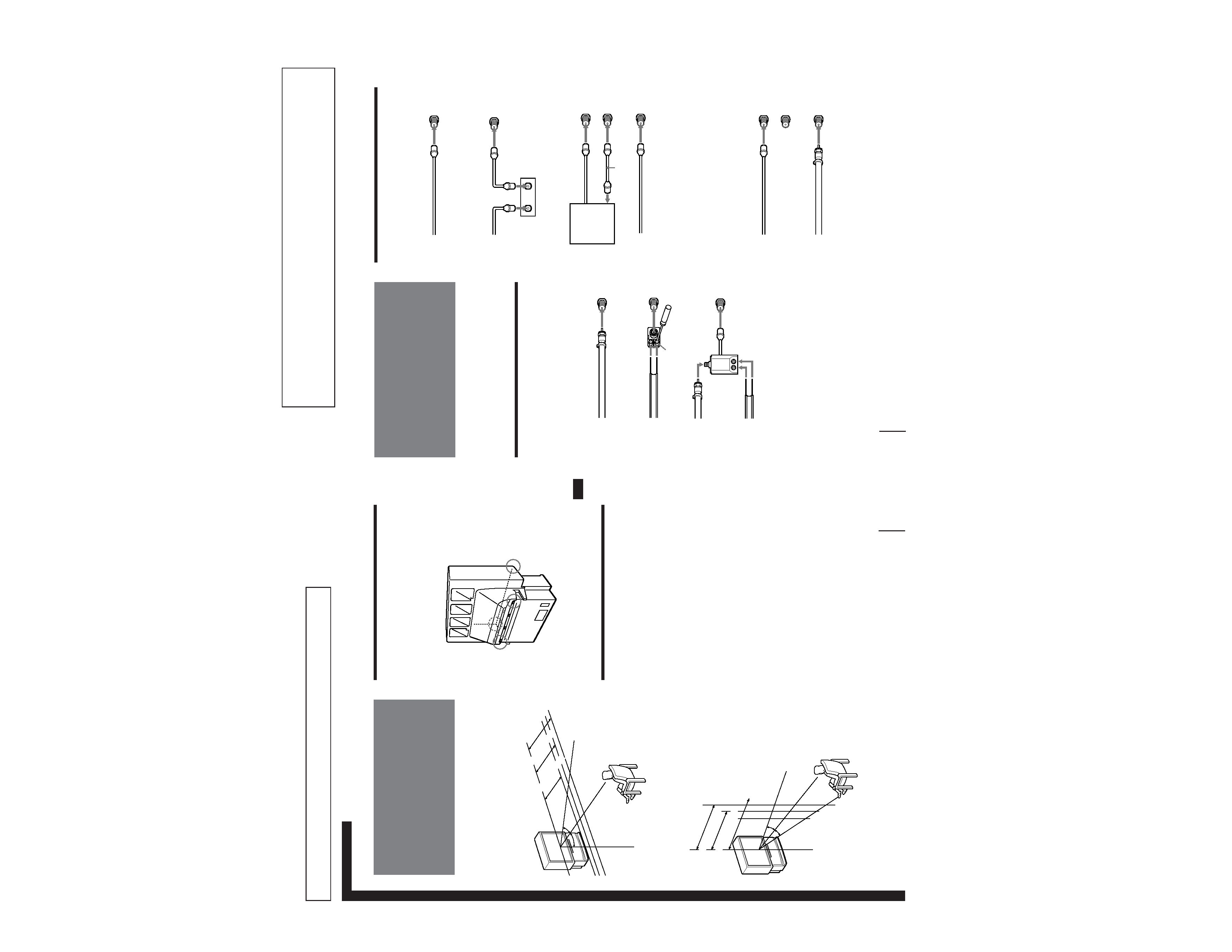
Getting Started
Step 2: Hookup
Connecting an antenna/cable TV
system without a VCR
To cable or antenna
Although you can use either an indoor or outdoor
antenna with your projection TV, we recommend that
you connect an outdoor antenna or a cable TV system
to get better picture quality.
Connecting an antenna
Connect your antenna cable to the VHF/UHF antenna
terminal. If you cannot connect your antenna cable
directly to the terminal, follow one of the instructions
below depending on your cable type.
To cable box and cable
Pay cable TV systems use scrambled or encoded signals
requiring a cable box* in addition to the normal cable
connection.
* The cable box will be supplied by the cable company.
Note
· You cannot watch the signal through an AUX connector as a
window picture.
To cable and antenna
Note
· Do not connect anything to the TO CONVERTER connector in
this case.
A
75-ohm coaxial cable
B
· VHF only
or
· UHF only
or
· VHF/UHF
C
Notes
· Most VHF/UHF combination antennas have a signal splitter.
Remove the splitter before attaching the appropriate connector.
· If you use the U/V mixer, snow and noise may appear in the
picture when viewing cable TV channels over 37.
EAC-66 U/V mixer
(not supplied)
· VHF
and
· UHF
75-ohm coaxial cable
300-ohm twin lead cable
300-ohm twin lead cable
Antenna connector
· VHF only
or
· VHF/UHF
or
· Cable
(Rear of projection TV)
VHF/UHF
(Rear of projection TV)
VHF/UHF
(Rear of projection TV)
VHF/UHF
Cable
To cable box
If your cable company requires you to connect a cable
box, make the connection as follows:
(Rear of projection TV)
VHF/UHF
(Rear of projection TV)
VHF/UHF
Cable
Cable box
IN
OUT
CATV cable
75-ohm coaxial
cable (not supplied)
Cable box
TO
CONVERTER
VHF/UHF
(Rear of projection TV)
AUX
CATV cable
Antenna cable
TO
CONVERTER
VHF/UHF
(Rear of projection TV)
AUX
The instructions here list excerpts mainly form the KP-47V75/53V75
Owner`s Manual. Other models are mentioned only for points differing
from KP-47V75/53V75.
The Instruction Manual of KP-48V75K/53V75K
Getting Started
5-EN
EN
Carrying your projection TV
p
KP-48V75/53V75/53V75C only
Be sure to grasp the areas indicated when carrying the
projection TV, and to use more than two people.
p
KP-61V75 only
Carry your projection TV by the casters.
Preparing for your projection TV
Before you use your projection TV, adjust convergence.
For the procedure, see "Step 4: Setting up the projection
TV automatically (AUTO SET UP)" on page 21.
Getting Started
Step 1: Installing
the projection TV
For the best picture quality, install the projection TV
within the areas shown below.
Optimum viewing area (Horizontal)
Optimum viewing area (Vertical)
(Rear of projection TV)
min.
1.5m
(approx.
5 ft.)
41"
60°
60°
min.
1.8m
(approx.
6 ft.)
48"
min.
2.1m
(approx.
7 ft.)
53"
20°
min.
2.1m
(approx.
7 ft.)
53"
min.
1.8m
(approx.
6 ft.)
48"
min.
1.5m
(approx.
5 ft.)
41"
20°
5
Getting Started
7-EN
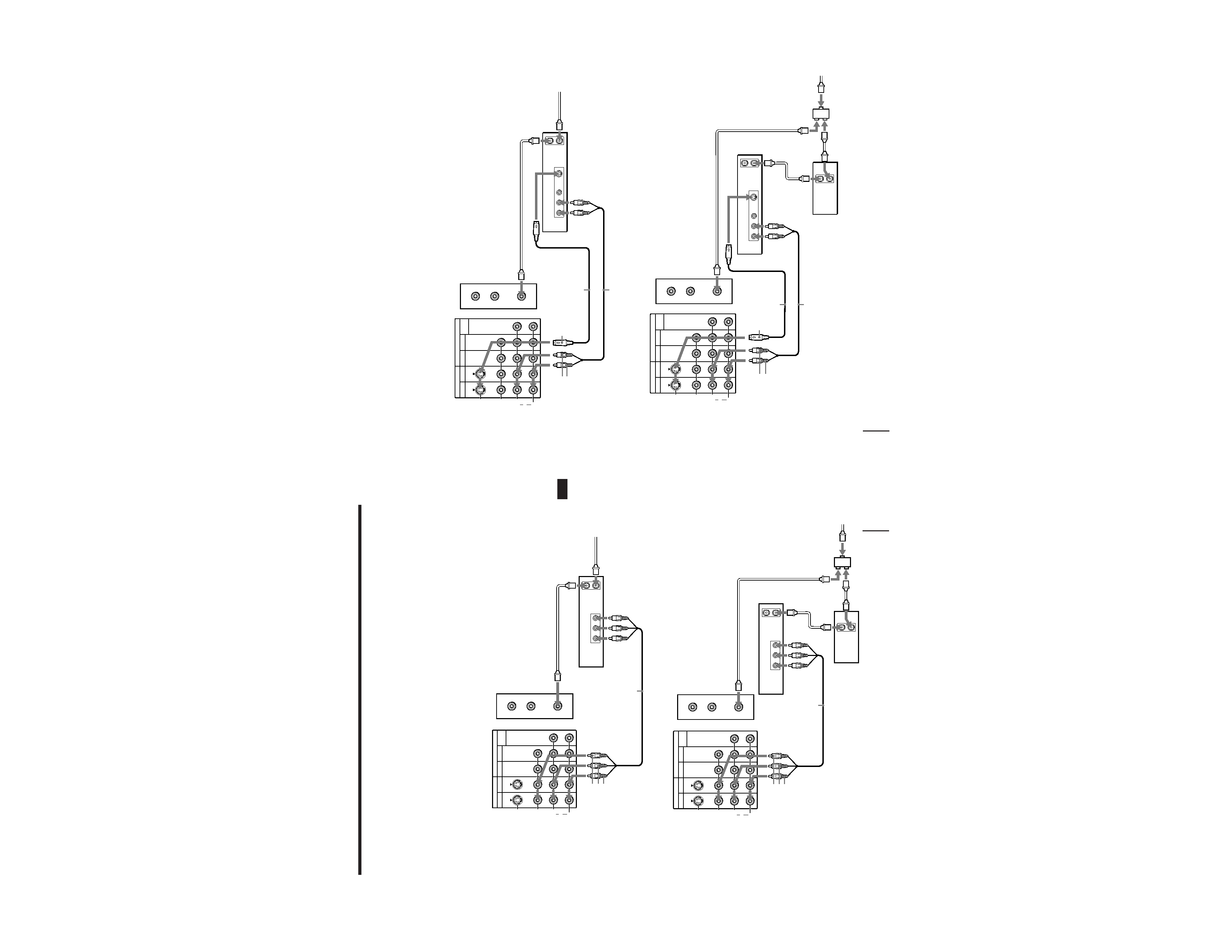
EN
Connecting an antenna/cable TV system with a VCR
After making these connections, you will be able to do
the following:
· View the playback of video tapes
· Record one TV program while viewing another
program
· Watch two TV programs at once using PIP
For details on connection, see your VCR instruction
manual.
Before making the connection, disconnect the AC
power cords of the equipment to be connected.
To a conventional VCR
Note
· To connect a monaural VCR, connect the audio output of the
VCR to AUDIO-L (MONO) of VIDEO 1/3 IN on the projection
TV.
Without a cable box
VIDEO (yellow)
AUDIO-L (white)
AUDIO-R (red)
Splitter (not supplied)
Antenna
cable
VIDEO (yellow)
AUDIO-L (white)
AUDIO-R (red)
VMC-810S/820S
(not supplied)
Antenna cable
VHF/UHF
Antenna cable
Rear of projection TV
VCR
With a cable box
VCR
Antenna cable
Cable box
VMC-810S/820S
(not supplied)
VHF/UHF
Video
and
audio
outputs
VHF/UHF
input
Video and audio
outputs
VHF/UHF
input
VHF/UHF
output
VHF/UHF
output
AUX
TO
CONVERTER
VHF/UHF
AUDIO VIDEO
LINE
OUT
OUT
IN
IN
VIDEO 1 VIDEO 3
S VIDEO
VIDEO
L
R
AUDIO
(MONO)
OUT
TV
MONITOR
AUDIO
(VAR/FIX)
OUT
IN
OUT
AUDIO VIDEO
LINE
OUT
IN
AUX
TO
CONVERTER
VHF/UHF
IN
VIDEO 1 VIDEO 3
S VIDEO
VIDEO
L
R
AUDIO
(MONO)
OUT
TV
MONITOR
AUDIO
(VAR/FIX)
Rear of projection TV
8-EN
Getting Started
Antenna cable
To an S video equipped VCR
If your VCR has an S VIDEO output connector, make
the following connections.
Whenever you connect the cable to the S VIDEO input
connector, the projection TV automatically receives S
video signals.
Without a cable box
With a cable box
S VIDEO
S VIDEO
Rear of projection TV
Note
· Video signals are composed of Y (luminance) and C (chroma)
signals. The S connection sends the two signals separately
preventing degradation, and gives better picture quality
compared to conventional connections.
RK-74A
(not supplied)
YC-15V/30V
(not supplied)
VCR
Antenna cable
Cable box
Splitter
(not supplied)
Antenna
cable
VHF/UHF
Antenna cable
YC-15V/30V
(not supplied)
RK-74A
(not supplied)
VHF/UHF
VCR
Audio
outputs
VHF/UHF
input
VHF/UHF
output
S video output
Audio
outputs
VHF/UHF
input
S video output
AUDIO-L (white)
AUDIO-R (red)
AUDIO-L (white)
AUDIO-R (red)
OUT
IN
AUDIO VIDEO S VIDEO
LINE
OUT
AUX
TO
CONVERTER
VHF/UHF
VIDEO 1 VIDEO 3
S VIDEO
VIDEO
L
R
AUDIO
(MONO)
TV
IN
OUT
MONITOR AUDIO
(VAR/FIX)
Rear of projection TV
AUX
TO
CONVERTER
VHF/UHF
AUDIO VIDEO S VIDEO
LINE
OUT
OUT
IN
OUT
IN
VIDEO 1 VIDEO 3
S VIDEO
VIDEO
L
R
AUDIO
(MONO)
TV
IN
OUT
MONITOR AUDIO
(VAR/FIX)