CHASSIS
RA-2A
SERVICE MANUAL
MODEL
COMMANDER
DEST. CHASSIS NO.
KP-41T65C
RM-Y136A
Chile SCC-N88A-A
KP-53S65C RM-Y136A
Chile SCC-N88B-A
KP-61S65C RM-Y136A
Chile SCC-N88C-A
MODEL
COMMANDER
DEST. CHASSIS NO.
MICROFILM
41
PROJECTION TV
53
61
Please file according to model size. .......
KP-61S65C
KP-41T65C
RM-Y136A
KP-53S65C

2
SPECIFICATIONS
Projection system
3 picture tubes, 3 lenses,
horizontal in-line system
Picture tube
7 inch high-brightness
monochrome tubes (6.3 raster
size), with optical coupling and
liquid cooling system
Projection lenses
High performance, large-
diameter hybrid lens F1.1
Screen size (measured diagonally)
Speaker
Full range speaker 100 mm (3.9
inches) diameter
Speaker output
15 W x 2
Power requirement
220 V, 50 Hz
Power consumption
165 W
Standby mode: 3 W
KP-41T65C
41 inches
KP-53S65C
53 inches
KP-61S65C
61 inches
KP-41T65C
KP-53S65C
KP-61S65C
Mass
55 kg
(121 lbs 4 oz)
69 kg
(152 lbs 1 oz)
122 kg
(268 lbs 15 oz)
Dimensions (W/H/D)
951 x 1,022 x 602 mm
(37 1/2 x 40 1/4 x 23 3/4 inches)
1,218 x 1,413 x 614 mm
(48 x 55 5/8 x 24 1/4 inches)
1,338 x 1,506 x 642 mm
(52 3/4 x 59 3/8 x 25 3/8 inches)
Television system
American TV standards
Channel coverage
VHF: 2 13 / UHF: 14 69 /
CATV: 1 125
Antenna
75 ohm external antenna
terminal for VHF/UHF
Inputs/output
VIDEO IN 1
VIDEO IN 2 (VIDEO 2 INPUT)
S VIDEO (4-pin mini DIN):
Y: 1 Vp-p, 75-ohms
unbalanced, sync negative
C: 0.286 Vp-p (Burst signal)
75 ohms
VIDEO (phono jack): 1 Vp-p,
75-ohms unbalanced, sync
negative
AUDIO (phono jacks): 500
mVrms (100% modulation)
Impedance : 47 kilohms
VIDEO IN 3
VIDEO (phono jacks): 1 Vp-p,
75-ohms unbalanced, sync
negative
AUDIO (phono jacks): 500
mVrms (100% modulation)
Impedance: 47 kilohms
MONITOR OUT
VIDEO (phono jack): 1 Vp-p,
75-ohms unbalanced, sync
negative
AUDIO (phono jacks): 500 mVrms
(100% modulation),
Impedance: 10 kilohms
AUDIO OUT (phono jacks): 900
mVrms (100% modulation)
Impedance: 5 kilohms
Supplied accessories
Remote control RM-Y136A (1)
Size AA (R6) battery (2)
Optional accessories
U/V mixer EAC-66
Connecting cables RK-74A, VMC-
810S/820S, YC-15V/30V, VMC-720M
Stand SU-41T2 (For KP-41T65C)
High-contrast protective screen
SCN-53X2 (For KP-53S65C)
SCN-61X2 (For KP-61S65C)
Design and specifications are subject to change without notice.

3
TABLE OF CONTENTS
Section
Title
Page
1. GENERAL
Step 1 : Installing the projection TV ....................................... 4
Step 2 : Hook up ...................................................................... 5
Step 3 : Setting up the remote control ..................................... 8
Step 4 : Setting up the projection TV automatically
(AUTO SET UP) ..................................................................... 9
Changing the menu larguage ................................................. 11
Watching the TV ................................................................... 11
Watching tow programs at one time-PIP ............................... 12
Freezing the picture (FREEZE) ............................................ 13
Adjusting the picture (VIDEO) ............................................. 13
Adjusting the color temperature (TRINITONE) ................... 14
Selecting the video mode (VIDEO) ...................................... 14
Adjusting the sound (AUDIO) .............................................. 14
Using audio effect (SURROUND) ........................................ 15
Selecting stereo or bilingual programs (MTS) ...................... 15
Setting the speaker switch (SPEAKER) ............................... 15
Setting audio out (AUDIO OUT) .......................................... 16
Setting daylight saving time (DAYLIGHT SAVING) .......... 16
Setting the clock (CURRENT TIME SET) ........................... 16
Setting the timer to turn the projection TV on and off
(ON/OFF TIMER) ................................................................ 17
Customizing the channel names (CHANNEL CAPTION) ... 17
Blocking out a channel (CHANNEL BLOCK) .................... 18
Setting your favorite channels (FAVORITE CHANNEL) .... 18
Setting video labels (VIDEO LABEL) ................................. 18
Setting Caption Vision (CAPTION VISION) ....................... 19
Operating video equipment ................................................... 19
Operating a cable box or DBS receiver ................................. 20
Troubleshooting .................................................................... 21
Index to parts and controls .................................................... 21
2. DISASSEMBLY
2-1.
Rear Board Removal .................................................. 23
2-2.
Chassis Assy Removal ................................................ 23
2-3.
Service Position .......................................................... 23
2-4-1. HA Board Removal (KP-41T65C) ............................. 24
2-4-2. HA Board Removal (KP-53S65C/61S65C) ............... 24
2-5-1. Beznet Assy Removal (KP-41T65C) .......................... 25
2-5-2. Beznet Assy Removal (KP-53S65C) .......................... 25
2-5-3. Screen Frame Assy Removal (KP-61S65C) ............... 25
2-6-1. Mirror Cover Assy Removal (KP-41T65C) ............... 26
2-6-2. Mirror Cover Assy Removal (KP-53S65C/61S65C) ...... 26
2-6-3. Reflection Mirror Removal (KP-61S65C) ................. 26
Section
Title
Page
2-7.
High-Voltage Cable Installation and Removal ........... 27
2-8-1. Picture Tube Removal (KP-41T65C) ......................... 27
2-8-2. Picture Tube Removal (KP-53S65C/61S65C) ............. 27
2-9-1. Service stay Assy How to use and Carry Back Service
stay Assy ..................................................................... 28
2-9-2. Picture Tube Bracket Assy Removal (KP-41T65C) ... 28
2-9-3. Picture Tube BracketAssy Removal (KP-53S65C/61S65C) . 29
2-9-4. Setting of Service stay Assy (KP-53S65C) ................ 30
2-9-5. Install a Chassis Assy ................................................. 30
3. SET-UP ADJUSTMENTS .................................................. 31
4. SAFETY RELATEDP ADJUSTMENTS .................... 44
5. CIRCUIT ADJUSTMENTS ................................................ 46
6. DIAGRAMS
6-1. Block Diagram (1) .......................................................... 49
Block Diagram (2) .......................................................... 52
Block Diagram (3) .......................................................... 54
6-2. Frame Schematic Diagram ............................................. 55
6-3. Circuit Boards Location ................................................. 58
6-4. Printed Wiring Boards and Schematic Diagrams ........... 58
· A Board ........................................................................ 59
· G Board ........................................................................ 66
· PT Board ...................................................................... 73
· CR, CG, CB Boards ..................................................... 79
· Z Board ........................................................................ 83
· HA Board ..................................................................... 85
· F Board ........................................................................ 87
6-5. Semiconductors .............................................................. 88
7. EXPLODED VIEWS
7-1. Cover (KP-41T65C) ....................................................... 90
7-2. Cover (KP-53S65C) ....................................................... 91
7-3. Cover (KP-61S65C) ....................................................... 92
7-4. Chassis (KP-41T65C) .................................................... 93
7-5. Chassis (KP-53S65C/61S65C) ........................................ 94
7-6. Picture Tube (KP-41T65C) ............................................ 95
7-7. Picture Tube (KP-53S65C/61S65C) ............................... 96
8. ELECTRICAL PARTS LIST ............................................. 97
(CAUTION)
SHORT CIRCUIT THE ANODE OF THE PICTURE TUBE AND
THE ANODE CAP TO THE METAL CHASSIS, CRT SHIELD, OR
CARBON PAINTED ON THE CRT, AFTER REMOVING THE AN-
ODE.
WARNING!!
AN ISOLATION TRANSFORMER SHOULD BE USED DURING
ANY SERVICE TO AVOID POSSIBLE SHOCK HAZARD, BE-
CAUSE OF LIVE CHASSIS.
THE CHASSIS OF THIS RECElVER IS DIRECTLY CONNECT-
ED TO THE AC POWER LINE.
SAFETY-RELATED COMPONENT WARNING!!
COMPONENTS IDENTIFIED BY SHADING AND MARK
! ON
THE SCHEMATIC DIAGRAMS, EXPLODED VIEWS AND IN THE
PARTS LIST ARE CRITICAL TO SAFE OPERATION. REPLACE
THESECOMPONENTS WITH SONY PARTS WHOSE PART NUM-
BERS APPEAR AS SHOWN IN THIS MANUAL OR IN SUPPLE-
MENTS PUBLISHED BY SONY. CIRCUIT ADJUSTMENTS THAT
ARE CRITICAL TO SAFEOPERATION ARE IDENTIFIED IN THIS
MANUAL. FOLLOW THESE PROCEDURES WHENEVER CRITI-
CAL COMPONENTS ARE REPLACED OR IMPROPER OPERA-
TION IS SUSPECTED.
4
SECTION 1
GENERAL
The operating instructions mentioned here partial abstracts from the
Operating Instructions Manual. The page numbers of the Operating
Instruction Manual remain as in the manual.
4-EN
Welcome!
Thank you for purchasing the Sony Color Rear Video
Projection TV. Here are some of the features you will
enjoy with your projection TV:
· On-screen menus that let you set the picture quality,
sound, and other settings.
· Two tuner Picture-in-Picture (PIP) that allows you
to watch another TV channel, video or cable image
as a window picture.
· Surround system that simulates the sound quality of
a concert hall or movie theater.
· SAVA SPEAKER option of the AUDIO menu that
lets you take advantage of the Sony SAVA series
speaker system's surround sound and super woofer
mode when you connect it to the projection TV.
About this manual
The instructions in this manual are for models KP-
41T65, KP-46C65, KP-48S65, KP-53S65, and KP-61S65.
Before you start reading this manual, please check your
model number, located at the rear of the projection TV.
Model KP-53S65 is used for illustration purposes in this
manual. Any differences in operation are clearly
indicated in the text, for example "KP-61T65 only."
The differences in specifications are indicated in the
text.
Instructions in this manual are based on use of the
remote control. You can also use the controls on the
projection TV if they have the same name as those on
the remote control.
Precautions
This projection TV operates on extremely high voltage.
To prevent fire or electric shock, please follow the
precautions below.
Safety
· Operate the projection TV only on 120 V AC.
· One blade of the plug is wider than the other for safety
purposes and will fit into the power outlet only one
way. If you are unable to insert the plug fully into the
outlet, contact your dealer.
· Should any liquid or solid object fall into the cabinet,
unplug the projection TV and have it checked by
qualified personnel before operating it further.
· Unplug the projection TV from the wall outlet if you
are not going to use it for several days or more. To
disconnect the cord, pull it out by the plug. Never
pull the cord itself.
For details concerning safety precautions, see the supplied
leaflet "IMPORTANT SAFEGUARDS."
Note on cleaning
Clean the cabinet of the projection TV with a dry soft
cloth. To remove dust from the screen, wipe it gently
with a soft cloth using vertical strokes only. Stubborn
stains may be removed with a cloth slightly dampened
with solution of mild soap and warm water. Never use
strong solvents such as thinner or benzine for cleaning.
If the picture becomes dark after using the projection TV
for a long period of time, it may be necessary to clean the
inside of the projection TV. Consult qualified service
personnel.
Installing
· To prevent internal heat build-up, do not block the
ventilation openings.
· Do not install the projection TV in a hot or humid
place, or in a place subject to excessive dust or
mechanical vibration.
· Avoid operating the projection TV at temperatures
below 5
°C (41°F).
· If the projection TV is transported directly from a cold
to a warm location, or if the room temperature has
changed suddenly, the picture may be blurred or show
poor color. This is because moisture has condensed on
the mirror or lenses inside. If this happens, let the
moisture evaporate before using the projection TV.
· To obtain the best picture, do not expose the screen to
direct illumination or direct sunlight. It is
recommended to use spot lighting directed down from
the ceiling or to cover the windows that face the screen
with opaque drapery. It is desirable to install the
projection TV in a room where the floor and walls are
not of reflecting material. If necessary, cover them
with dark carpeting or wall paper.
Getting Started
5-EN
EN
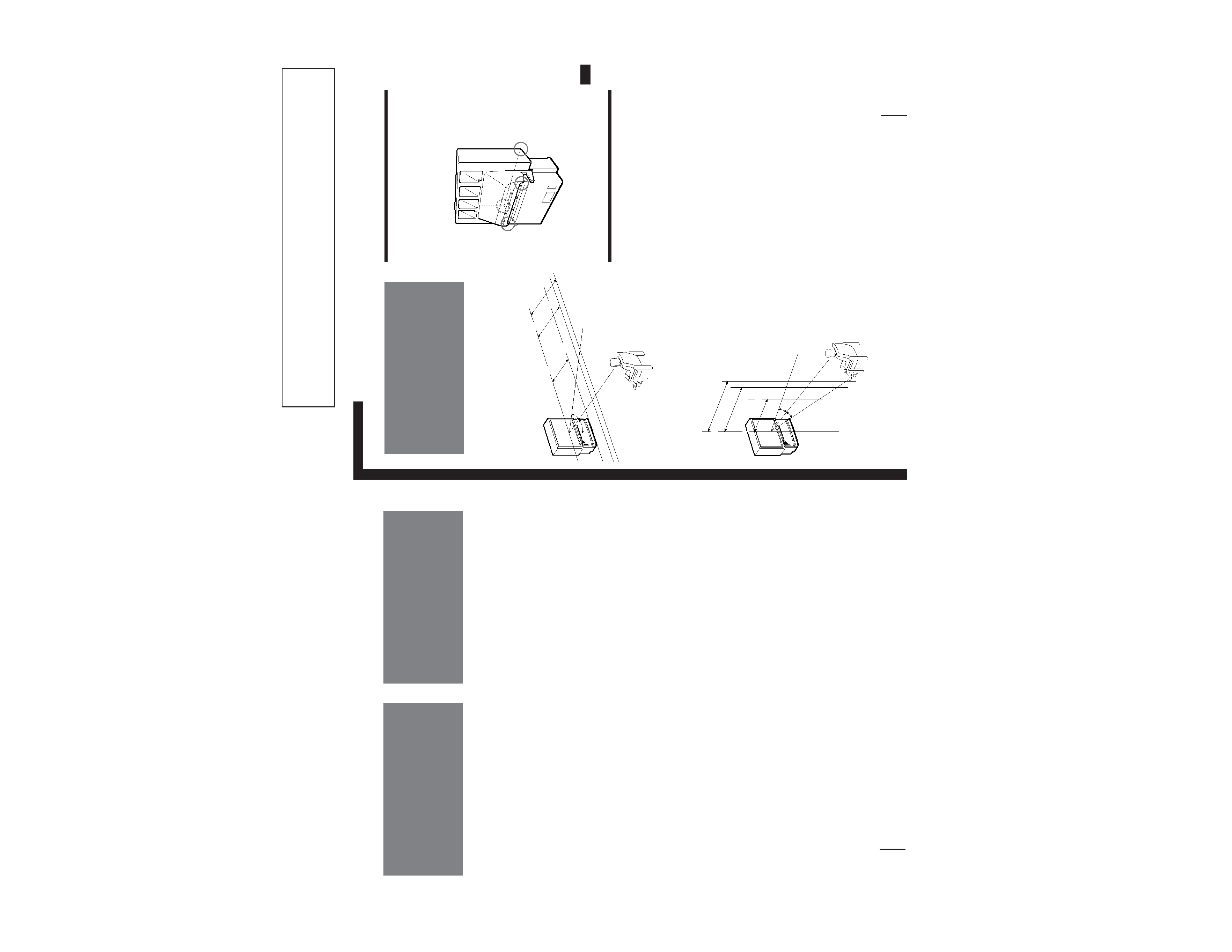
Carrying your projection TV
p KP-41T65C/53S65C only
Be sure to grasp the areas indicated when carrying the
projection TV, and to use more than two people.
p KP-61S65C only
Carry your projection TV by the casters.
Preparing for your projection TV
Before you use your projection TV, adjust convergence.
For the procedure, see Step 4: Setting up the projection
TV automatically (AUTO SET UP) on page 14.
Getting Started
Step 1: Installing
the projection TV
For the best picture quality, install the projection TV
within the areas shown below.
Optimum viewing area (Horizontal)
Optimum viewing area (Vertical)
(Rear of projection TV)
60
°
min.
2.1m
(approx.
7 ft.)
53"
min.
1.5m
(approx.
5 ft.)
41"
min.
2.4m
(approx.
8 ft.)
61"
60
°
60
°
min.
2.1m
(approx.
7 ft.)
53"
min.
1.5m
(5 ft.)
41"
min.
1.5m
(5 ft.)
41"
min.
2.4m
(approx.
8 ft.)
61"
20
°
20
°
5
Getting Started
7-EN
EN
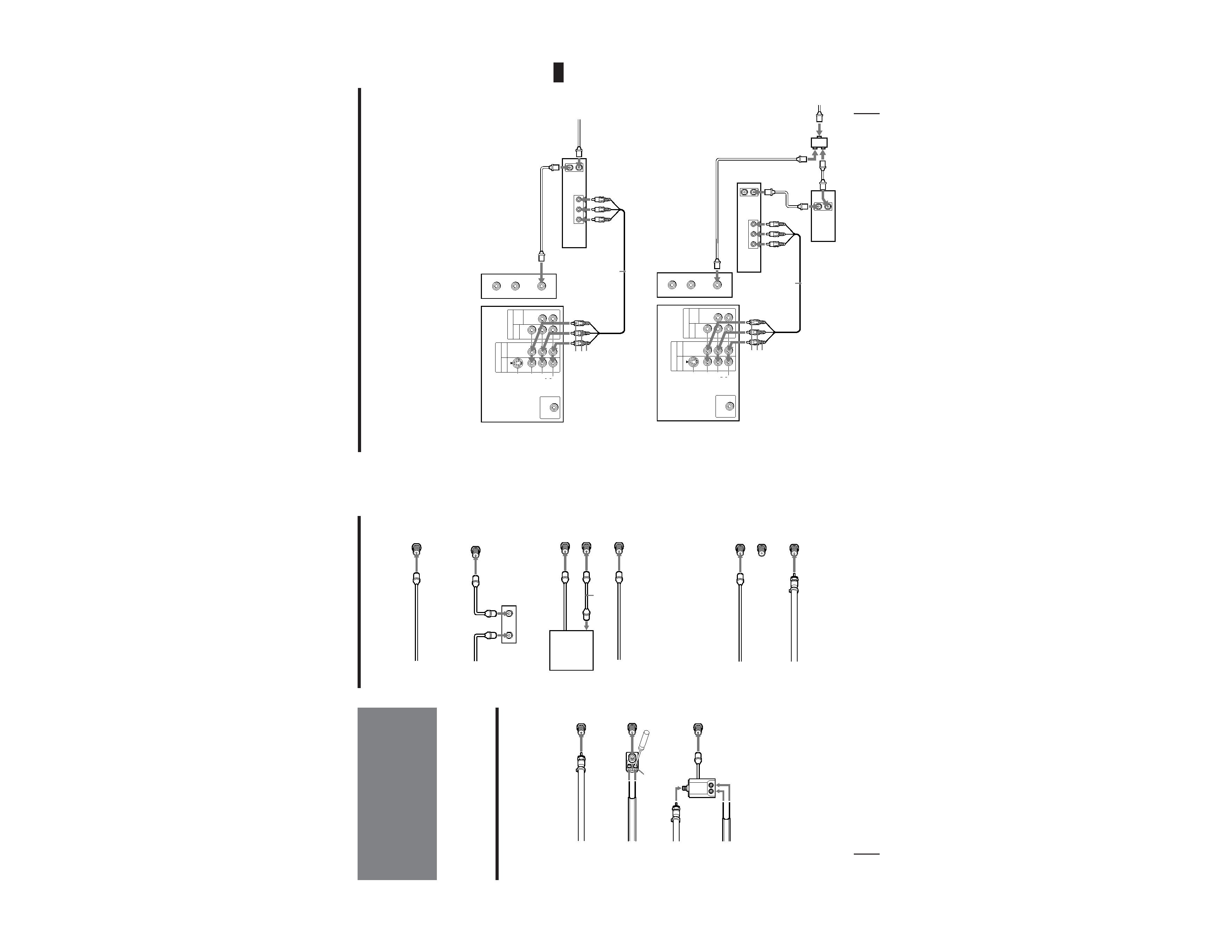
Connecting an antenna/cable TV system with a VCR
After making these connections, you will be able to do
the following:
· View the playback of video tapes
· Record one TV program while viewing another
program
· Watch two TV programs at once using PIP
For details on connection, see your VCR instruction
manual.
Before making the connection, disconnect the AC power
cords of the equipment to be connected.
To a conventional VCR
Notes
· To connect a monaural VCR, connect the audio output of the VCR
to AUDIO-L (MONO) of VIDEO 1/2/3 IN on the projection TV.
Without a cable box
VIDEO (yellow)
AUDIO-L (white)
AUDIO-R (red)
(Rear of projection TV)
Splitter (not supplied)
Antenna
cable
VIDEO (yellow)
AUDIO-L (white)
AUDIO-R (red)
VMC-810S/820S
(not supplied)
Antenna cable
VHF/UHF
Antenna cable
(Rear of projection TV)
VCR
With a cable box
VCR
Antenna cable
Cable box
VMC-810S/820S
(not supplied)
VHF/UHF
Video
and
audio
outputs
VHF/UHF
input
Video and audio
outputs
VHF/UHF
input
VHF/UHF
output
VHF/UHF
output
(VAR/FIX)
IN
VIDEO 1 VIDEO 3
S VIDEO
VIDEO
L
R
AUDIO
(MONO)
OUT
MONITOR AUDIO
CONTROL S
OUT
AUX
TO
CONVERTER
VHF/UHF
AUDIO VIDEO
LINE
OUT
OUT
IN
OUT
IN
OUT
AUDIO VIDEO
LINE
OUT
IN
(VAR/FIX)
IN
VIDEO 1 VIDEO 3
S VIDEO
VIDEO
L
R
AUDIO
(MONO)
OUT
MONITOR AUDIO
CONTROL S
OUT
AUX
TO
CONVERTER
VHF/UHF
6-EN
Getting Started
Step 2: Hookup
Connecting an antenna/cable TV
system without a VCR
To cable or antenna
Although you can use either an indoor or outdoor
antenna with your projection TV, we recommend that
you connect an outdoor antenna or a cable TV system
to get better picture quality.
Connecting an antenna
Connect your antenna cable to the VHF/UHF antenna
terminal. If you cannot connect your antenna cable
directly to the terminal, follow one of the instructions
below depending on your cable type.
To cable box and cable
Pay cable TV systems use scrambled or encoded signals
requiring a cable box* in addition to the normal cable
connection.
* The cable box will be supplied by the cable company.
Note
· You cannot watch the signal through an AUX connector as a
window picture.
To cable and antenna
Note
· Do not connect anything to the TO CONVERTER connector in
this case.
A
75-ohm coaxial cable
B
· VHF only
or
· UHF only
or
· VHF/UHF
C
Notes
· Most VHF/UHF combination antennas have a signal splitter.
Remove the splitter before attaching the appropriate connector.
· If you use the U/V mixer, snow and noise may appear in the
picture when viewing cable TV channels over 37.
EAC-66 U/V mixer
(not supplied)
· VHF
and
· UHF
75-ohm coaxial cable
300-ohm twin lead cable
300-ohm twin lead cable
Antenna connector
· VHF only
or
· VHF/UHF
or
· Cable
(Rear of projection TV)
VHF/UHF
(Rear of projection TV)
VHF/UHF
(Rear of projection TV)
VHF/UHF
Cable
To cable box
If your cable company requires you to connect a cable
box, make the connection as follows:
(Rear of projection TV)
VHF/UHF
(Rear of projection TV)
VHF/UHF
Cable
Cable box
IN
OUT
CATV cable
75-ohm coaxial
cable (not supplied)
Cable box
TO
CONVERTER
VHF/UHF
(Rear of projection TV)
AUX
CATV cable
Antenna cable
TO
CONVERTER
VHF/UHF
(Rear of projection TV)
AUX