CHASSIS
MODEL
MODEL
SERVICE MANUAL
MICROFILM
CHASSIS No.
CHASSIS No.
COMMANDER
DEST.
COMMANDER DEST.
..................
.......................... ............
........................
..................
.......................... ............
........................
LCD PROJECTION DATA MONITOR
50
* Please file according to model size...
LM-1
KL-X9200U
KL-X9200U
KL-X9200M
KL-X9200M
SCC-P04A-A
SCC-P04A-A
RM-902
RM-902
AEP
E
RM-902
RM-902
US
Canadian
SCC-P03A-A
SCC-P03A-A

2
KL-X9200M/X9200U
RM-902
Specifications
Acceptable signal
(Appendix)
NTSC3.58/NTSC4.43/PAL/PAL M
/SECAM video signal, switched
automatically
RGB signal
Projection system
3 LCD panels, 1 lens projection
system
LCD panel
1.3-inch TFT LCD panel
Approx. 2.36 million dots
(786,432 pixels)
1,024
× 768 dots × 3 panels
Lamp
XL-100M: HID lamp, 100 W
Lens
Large diameter hybrid lens F2.4
Screen size (measured diagonally)
50 inches
Viewable image size
Approx. 50 inches (diagonally)
Approx. 1,016
× 762 mm (w/h)
Frequency range
Horizontal: 24.8 to 85 kHz
Vertical: 50 to 85 Hz
Inputs/outputs
VIDEO 1, 2 and 3 IN S VIDEO (4-pin mini-DIN):
Y: 1 Vp-p, 75 ohms
unbalanced, sync negative
C: 0.286 Vp-p (NTSC burst
signal), 75 ohms
0.3 Vp-p (PAL burst signal), 75
ohms
VIDEO (phono jacks):
1 Vp-p, 75 ohms unbalanced,
sync negative
AUDIO (phono jacks):
2 channels, 500 mVrms
Impedance: more than 47
kohms
COMPONENT IN
VIDEO (phono jacks):
Y: 1 Vp-p, 75 ohms, sync
negative
PB/CB/B-Y: 0.7 Vp-p, 75 ohms
PR/CR/R-Y: 0.7 Vp-p, 75 ohms
AUDIO (phono jacks): 500
mVrms (100% modulation)
Impedance: 47 kilohms
VIDEO OUT
S VIDEO (4-pin mini-DIN):
Y: 1 Vp-p, 75 ohms
unbalanced, sync negative
C: 0.286 Vp-p (NTSC burst
signal), 75 ohms
0.3 Vp-p (PAL burst signal), 75
ohms
VIDEO (phono jack):
1 Vp-p, 75 ohms unbalanced,
sync negative
AUDIO (phono jacks):
2 channels, 500 mVrms
Impedance: less than 1 kohms
RGB 1, 2 IN
D-sub 15-pin, female
VIDEO: R, G, B: 0.7 Vp-p,
positive, 75 ohms
SYNC: Sync on Green: 0.3 Vp-p
HD: Composite sync:
TTL, high impedance,
sync positive/negative
Horizontal sync: TTL, high
impedance, sync positive/
negative
VD: Vertical sync: TTL, high
impedance, sync positive/
negative
AUDIO (phono jacks)
2 channels, 500 mVrms
Impedance: more than 47 kohms
RGB OUT
D-sub 15-pin, female
VIDEO: R, G, B: 0.7 Vp-p,
positive, 75 ohms
SYNC: Sync on Green: 0.3 Vp-p
HD: Composite sync:
TTL, high impedance,
sync positive/negative
Horizontal sync: TTL, high
impedance, sync positive/
negative
VD: Vertical sync: TTL, high
impedance, sync positive/
negative
AUDIO (phono jacks)
2 channels, 500 mVrms
Impedance: less than 1 kohm
Speaker output
Front: 5 W
× 2 (L/R)
Woofer: 15 W
Power requirement
100 to 240 V AC, 50/60 Hz
Power consumption
220 W (MAX)
Standby mode: 4 W
Dimensions
1,125
× 1,087 × 610 mm (44 3/8 × 42
7/8
× 24 1/8 inches) (w/h/d)
Mass
Approx. 43 kg (106 lbs 8 oz)
Supplied accessories
Remote control RM-902 (1)
Size AA (R6) batteries (2)
AC power cord (1)
RGB signal cable (D-sub 15-pin
~ D-sub 15-pin) (1)
HD15-HD15 (male, without the
No. 9 pin) adaptor (1)
Macintosh adaptor (1)
Windows Monitor Information
Disk/Utility Disk (1)
Macintosh Utility Disk (1)
Brackets (2)
Screws for brackets (2)
Hexagon head wrench (1)
Optional accessories
Lamp unit: XL-100 (for Japan),
XL-100U (only for the U.S.),
XL-100M (for countries other
than Japan or the U.S.)
Monitor stand: SU-90T (only for
Japan), SU-90U (only for the
U.S.)
Design and specifications are subject to change without
notice.
3
KL-X9200M/X9200U
RM-902
SAFETY CHECK-OUT
(US Model only)
LEAKAGE TEST
The AC leakage from any exposed metal part to earth ground
and from all exposed metal parts to any exposed metal part having a
return to chassis, must not exceed 0.5 mA (500 microampers).
Leakage current can be measured by any one of three methods.
1. A commercial leakage tester, such as the Simpson 229 or
RCA WT-540A. Follow the manufacturers' instructions to
use these instruments.
2. A battery-operated AC milliammeter. The Data Precision 245
digital multimeter is suitable for this job.
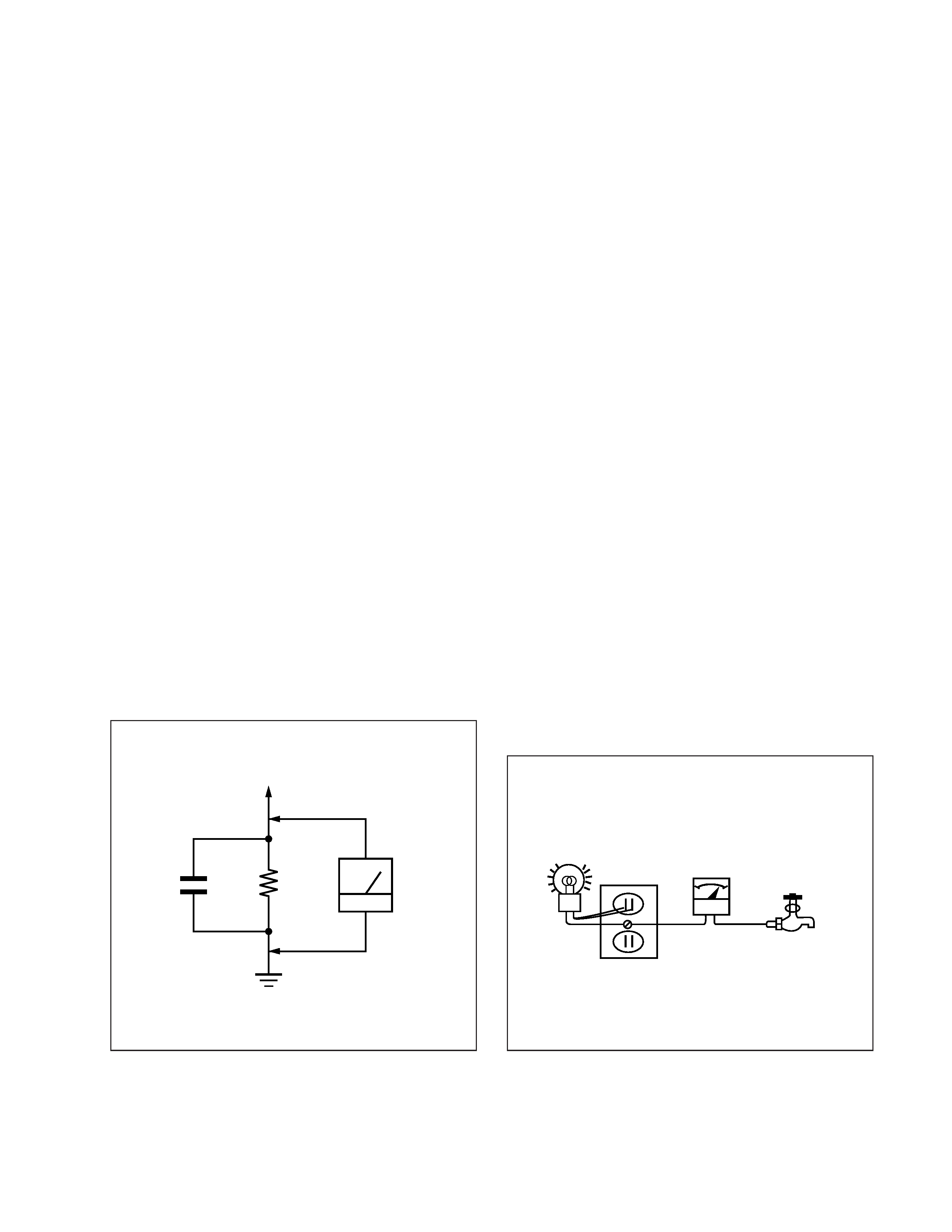
3. Measuring the voltage drop across a resistor by means of a
VOM or battery-operated AC voltmeter. The "limit" indica-
tion is 0.75 V, so analog meters must have an accurate low-
voltage scale. The Simpson 250 and Sanwa SH-63Trd are ex-
amples of a passive VOMs that are suitable. Nearly all battery
operated digital multimeters that have a 2 V AC range are suit-
able. (See Fig. A)
HOW TO FIND A GOOD EARTH GROUND
A cold-water pipe is guaranteed earth ground; the cover-plate
retaining screw on most AC outlet boxes is also at earth ground. If
the retaining screw is to be used as your earth-ground, verify that it
is at ground by measuring the resistance between it and a cold-
water pipe with an ohmmeter. The reading should be zero ohms. If
a cold-water pipe is not accessible, connect a 60 100 watts
trouble light (not a neon lamp) between the hot side of the recep-
tacle and the retaining screw. Try both slots, if necessary, to locate
the hot side of the line, the lamp should light at normal brilliance if
the screw is at ground potential. (See Fig. B)
After correcting the original service problem, perform the fol-
lowing safety checks before releasing the set to the customer:
1. Check the area of your repair for unsoldered or poorly-sol-
dered connections. Check the entire board surface for solder
splashes and bridges.
2. Check the interboard wiring to ensure that no wires are
"pinched" or contact high-wattage resistors.
3. Check that all control knobs, shields, covers, ground straps,
and mounting hardware have been replaced. Be absolutely
certain that you have replaced all the insulators.
4. Look for unauthorized replacement parts, particularly transis-
tors, that were installed during a previous repair. Point them
out to the customer and recommend their replacement.
5. Look for parts which, though functioning, show obvious signs
of deterioration. Point them out to the customer and recom-
mend their replacement.
6. Check the line cords for cracks and abrasion. Recommend the
replacement of any such line cord to the customer.
7. Check the condition of the monopole antenna (if any).
Make sure the end is not broken off, and has the plastic cap on
it. Point out the danger of impalement on a broken antenna to
the customer, and recommend the antenna's replacement.
8. Check the B+ and HV to see if they are specified values. Make
sure your instruments are accurate; be suspicious of your HV
meter if sets always have low HV.
9. Check the antenna terminals, metal trim, "metallized" knobs,
screws, and all other exposed metal parts for AC Leakage.
Check leakage as described below.
1.5 k W
0.15 µF
AC
Voltmeter
(0.75 V)
To Exposed Metal
Parts on Set
Earth Ground
Fig. A. Using an AC voltmeter to check AC leakage.
Trouble Light
AC Outlet Box Ohmmeter
Cold-water Pipe
Fig. B. Checking for earth ground.

4
KL-X9200M/X9200U
RM-902
TABLE OF CONTENTS
Section
Title
Page
Section
Title
Page
1. SELF DIAGNOSIS FUNCTION
1-1.
An Outline of Self Diagnosis Function ...............
5
1-2.
Diagnosis Items and Surmise ..............................
5
1-3.
Indication of Self Diagnosis ................................
6
1-4.
How to Finish the Self Diagnosis ........................
6
1-5.
Self Diagnosis Circuit (A BOARD) ....................
7
2. GENERAL ..................................................................
8
3. DISASSEMBLY
3-1.
Rear Cover Assembly Removal .......................... 23
3-2.
Chassis Assembly Removal ................................ 23
3-3.
Service Position ................................................... 23
3-4
Power Block , K Board Removal ........................ 23
3-5.
G Board Removal ................................................ 24
3-6.
U Board Removal ................................................ 24
3-7.
BB Board and BD Board Removal ..................... 24
3-8.
Inspection Method of the BB Board .................... 24
3-9.
A Board Removal ................................................ 25
3-10.
Filter Removal ..................................................... 25
3-11.
Lamp Block Removal .......................................... 25
3-12.
Pedestal Removal ................................................ 25
3-13.
HB Board Removal ............................................. 26
3-14.
HA Board Removal ............................................. 26
3-15.
Screen Frame Assembly Removal ....................... 27
3-16.
C Board and CU Board Removal ........................ 27
3-17.
Inspection Method of the C Board ...................... 28
3-18.
Optics Unit Removal ........................................... 28
4. CIRCUIT ADJUSTMENTS ................................ 29
5. DIAGRAMS
5-1.
Block Diagrams ................................................... 41
5-2.
Frame Schematic Diagrams ................................. 53
5-3.
Circuit Boards Location ....................................... 55
5-4.
Schematic Diagrams and Printed
Wiring Boards ................................................. 56
(1)
Schematic Diagrams of A Board (1/4) .................. 57
(2)
Schematic Diagram of A Board (2/4) ................... 61
(3)
Schematic Diagram of A Board (3/4) ................... 65
(4)
Schematic Diagram of A Board (4/4) ................... 68
(5)
Schematic Diagram of BB Board (1/5) ................. 79
(6)
Schematic Diagram of BB Board (2/5) ................. 82
(7)
Schematic Diagram of BB Board (3/5) ................. 85
(8)
Schematic Diagram of BB Board (4/5) ................. 88
(9)
Schematic Diagram of BB Board (5/5) ................. 91
(10) Schematic Diagram of BD Board (2/2) ................. 94
(11) Schematic Diagram of BD Board (1/2) ................. 97
(12) Schematic Diagram of G Board ............................ 101
(13) Schematic Diagram of HA Board ......................... 105
(14) Schematic Diagrams of HB, FR Boards ................ 107
(15) Schematic Diagram of K Board ............................ 109
(16) Schematic Diagrams of U, TA,TB Boards ............ 115
(17) Schematic Diagram of CU Board ......................... 119
(18) Schematic Diagram of C Board (1/3) .................... 123
(19) Schematic Diagram of C Board (2/3) .................... 124
(20) Schematic Diagram of C Board (3/3) .................... 127
5-5.
Semiconductors ................................................... 131
6. EXPLODED VIEWS
6-1.
Chassis Section .................................................... 133
6-2.
Front Section ....................................................... 134
6-3.
Screen Mirror Section .......................................... 135
6-4.
Optics Section ...................................................... 136
7. ELECTRICAL PARTS LIST ............................ 137
SAFETY-RELATED COMPONENT WARNING!!
COMPONENTS IDENTIFIED BY SHADING AND MARK
¡
ON THE SCHEMATIC DIAGRAMS, EXPLODED VIEWS
AND IN THE PARTS LIST ARE CRITICAL TO SAFE
OPERATION. REPLACE THESE COMPONENTS WITH
SONY PARTS WHOSE PART NUMBERS APPEAR AS
SHOWN IN THIS MANUAL OR IN SUPPLEMENTS
PUBLISHED BY SONY.
ATTENTION AUX COMPOSANTS RELATIFS À LA
SÉCURITÉ!!
LES COMPOSANTS IDENTIFIÉS PAR UNE TRAME ET
UNE MARQUE
¡ SONT CRITIQUES POUR LA
SÉCURITÉ. NE LES REMPLACER QUE PAR UNE PIÈCE
PORTANT LE NUMÉRO SPECIFIÉ. LES RÉGLAGES DE
CIRCUIT DONT L'IMPORTANCE EST CRITIQUE POUR
LA
SÉCURITÉ
DU
FONCTIONNEMENT
SONT
IDENTIFIÉS DANS LE PRÉSENT MANUEL. SUIVRE CES
PROCÉDURES LORS DE CHAQUE REMPLACEMENT DE
COMPOSANTS CRITIQUES, OU LORSQU'UN MAUVAIS
FONCTIONNE-MENT EST SUSPECTÉ.
5
KL-X9200M/X9200U
RM-902
SECTION 1
SELF DIAGNOSIS FUNCTION
1-1. AN OUTLINE OF SELF DIAGNOSIS FUNCTION
· This monitor is loaded DIAGNOSIS FUNCTION.
· STANDBY/LAMP lamp flashes when abnormal conditions happen. You can surmise what is wrong
by number of times of flashing.
· Flashing STANDBY/LAMP lamp is described in Operating Instruction Manual, and also informed to
customers .
· Sometimes the condition never be shown because of machine trouble. In such a case, the machine
memorizes that troubles have broken out. So you can check it on the screen with operating remote
commander and surmise what is wrong.
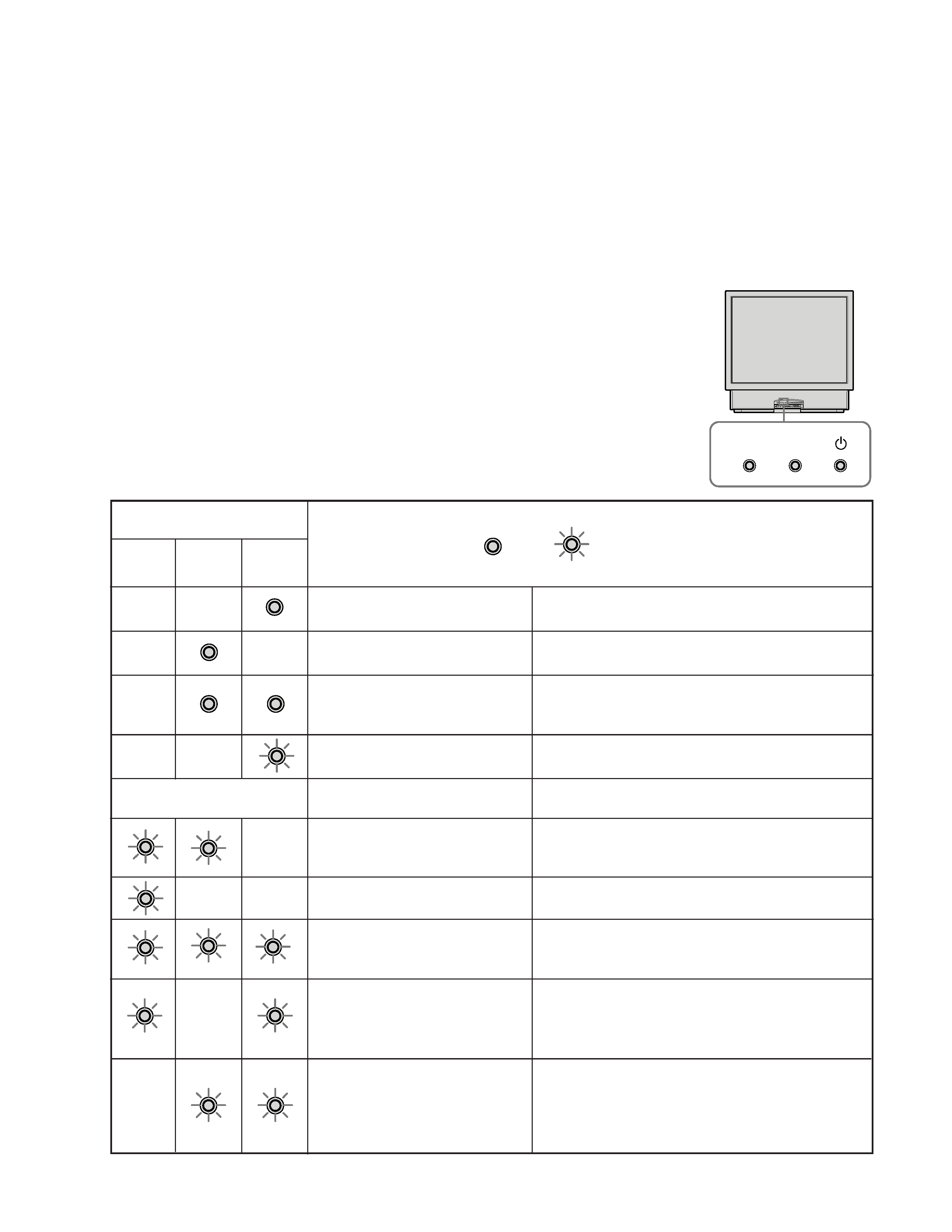
1-2. DIAGNOSIS ITEMS AND SURMISE
· STANDBY/LAMP lamp flashes only for one of the items listed below at once. When several
troubles break out continuously, the lamp indicates the first one, when several troubles break out at
once, the lamp indicates the item with smaller number of times of flashing.
· Results of all items listed below are indicated on the screen, and indicating "0" means no troubles.
INCOMPLETE INSTALLATION
OF THE LAMP COVER OR AIR
FILTER .
THE LAMP FOR THE LIGHT
SOURCE HAS BURNT OUT.
FAN IS WORKING ABNOR-
MALLY.
NO POWER SUPPLY FROM
POWER SOURCE TO THE LAMP
FOR THE LIGHT SOURCE
NO POWER SUPPLY FROM
POWER SOURCE TO THE
SWITCH.
INDICATION LAMP
LAMP STANDBY
u
(ORANGE) (ORANGE)
(GREEN)
: ON
: FLASH
OFF
The power of the monitor is on.
The monitor is in standby mode. The monitor is
turned on by pressing 1/u on the remote control.
The AUTO SHUT OFF function is working. The moni-
tor has been turned off when the time you specify has
passed after the input from the computer is cut off.
The lamp is preparing to turn on. Picture and sound
will appear momentarily.
The air filter or the lamp cover is not attached se-
curely. When you secure the cover, the STANDBY
indicator lights up and the LAMP indicator turns off.
The lamp for the light source has burnt out. Replace it
with a new one.
One of the fans, behind the optical unit, above the
lamp for the light source or behind, is not working.
Check the connector, power and fans.
No power is supplied from power source to power
supply circuit of the lamp for the light source. Check
the power supply from power source, control signal
from system control and power supply circuit.
6V DC is not supplied from power source (G board).
Control signal from system control may not be sent
normally, or may be power supply circuit is some-
thing wrong. Also it is possible that power from
switching power source short circuits GND.
POWER ON
STANDBY
OPERATING AUTO SHUT OFF
WAITING FOR THE LAMP FOR
THE LIGHT SOURCE
OFF
OFF
OFF
OFF
OFF
OFF
OFF
OFF
OFF
OFF
OFF
OFF
INDICATIONS FOR ABNOR-
MAL CONDITIONS
LAMP STANDBY