Ver.
DATA
CONTENTS
1.0
2003. 1
New
1.1
2005. 8
Addition of WARNING AND CAUTIONS (P.3)
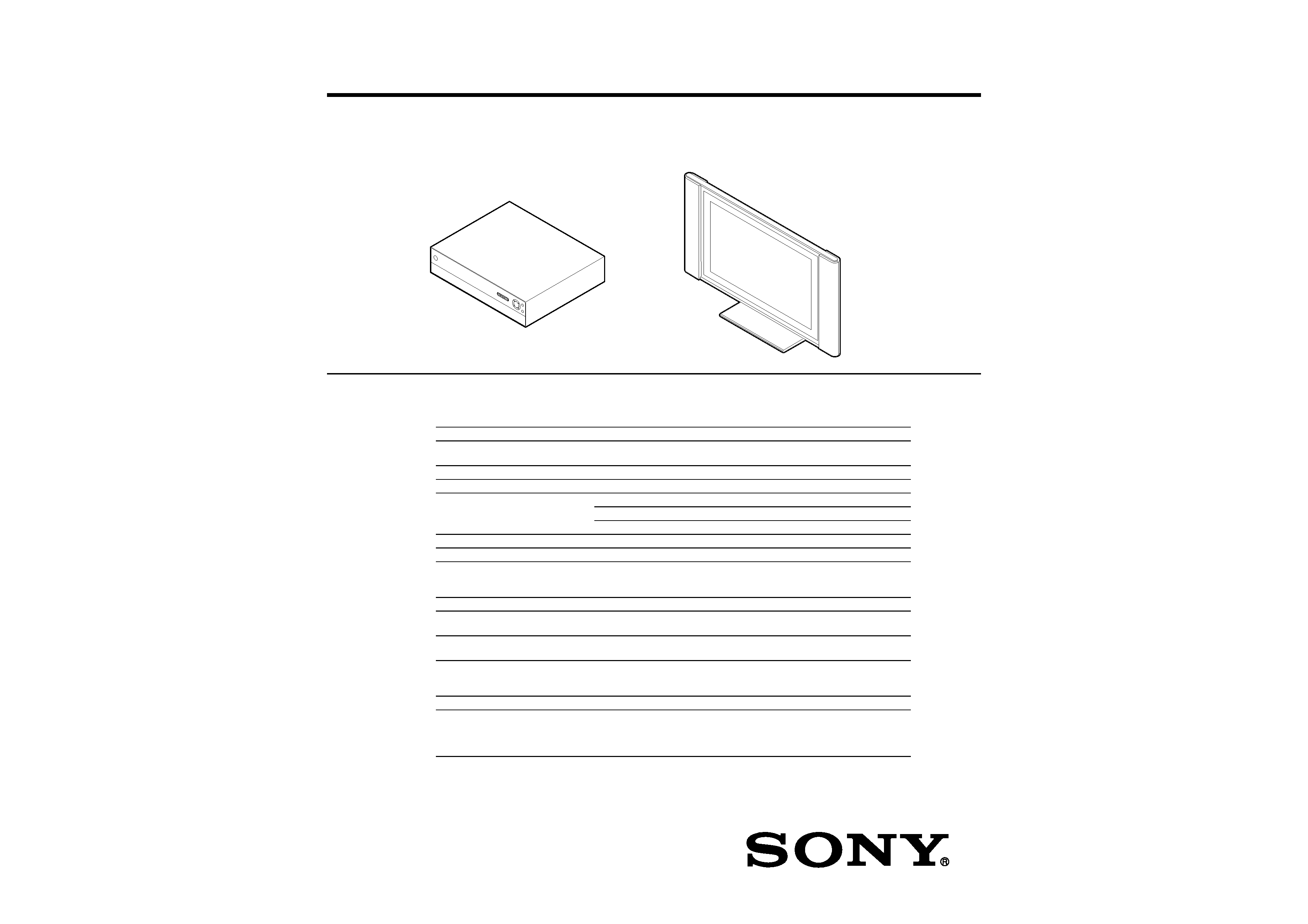
MODEL NAME : KLV-30XBR900
SERVICE MANUAL
PARTS No. : 9-978-761-02
MODIFICATION
HISTORY
* Blue characters are linking.
SERVICE MANUAL
SPECIFICATIONS
KLV-30XBR900
FLAT PANEL COLOR TV
US Model
Canadian Model
Panel System
Liquid Crystal Display panel
Display resolution
Display resolution:
1280 pixels (horizontal)
× 768 pixels (vertical)
Antenna
75 ohm external terminal for VHF/UHF
Television System
NTSC, American TV Standard
Channel Coverage
VHF
2-13
UHF
14-69
CATV
1-125
Power Requirements
120 V, 60 Hz
Inputs/Outputs
DVI-HDTV
1 terminal, 3.3V T.M.D.S., 50 ohms
The DVI-HDTV input terminal is compliant with the EIA-861 standard and is not
intended for use with personal computers.
Video (IN)
3 total (1 on front panel)
1 Vp-p, 75 ohms unbalanced, sync negative
S Video (IN)
3 total (1 on front panel)
Y: 1 Vp-p, 75 ohms unbalanced, sync negative
C: 0.286 Vp-p (Burst signal), 75 ohms
Audio (IN)
6 total (1 on front panel)
500 mVrms (100% modulation)
Impedance: 47 kilohm
Component Video Input
2 (Y, PB, PR)
Y: 1.0 Vp-p, 75 ohms unbalanced, sync negative;
PB: 0.7 Vp-p, 75 ohms
PR: 0.7 Vp-p, 75 ohms
CONTROL S (OUT)
1
Variable/Fixed Audio (OUT)
1
More than 408 mVrms at the maximum volume
setting (Variable)
More than 408 mVrms (Fixed)
Impedance (output): 2 kilohms
KLV-30XBR900(UC)
2
Design and specifications are subject to change without notice.
Power Consumption
In Use
Display unit
LDM-3000: 150 W
Media receiver unit
MBT-XBR900L: 36 W
In Standby
Under 1.5 W
Supplied Accessories
Remote Control (1)
RM-927Y
AAA (LR03) Batteries (2)
AC power code (2)
Display interface cable (1)
Antenna cable (1)
Monitor/Fixed Audio (OUT)
×1
Sub woofer (OUT)
1
phono jack
RF Inputs
2
Converter
1
Screen Size (measured diagonally)
30 inches
Speaker Output
10 w
× 2, 4 ohms
Dimensions (W
× H × D)
Display unit
LDM-3000: 971.2
× 594.4 × 229 mm (38 1/4 × 23 1/2 × 9 1/8 in) - with stand
971.2
× 524.3 × 93.4 mm (38 1/4 × 20 3/4 × 3 3/4 in) - without stand
Media receiver unit
MBT-XBR900L: 430
× 105 × 360 mm (17 × 4 1/4 × 14 1/4 in)
Mass
Display unit
LDM-3000: 27 Kg (59 lbs 60ozs) - with stand
20 Kg (44 lbs) - without stand
Media receiver unit
MBT-XBR900L: 7.5 Kg (16 lbs)

KLV-30XBR900(UC)
3
WARNING AND CAUTIONS
CAUTION
These servicing instructions are for use by qualified service personnel only To reduce the risk of electric shock, do not perform any
servicing other than that contained in the operating instructions unless you are qualified to do so.
WARNING!!
An isolation transformer should be used during any service to avoid possible shock hazard, because of live chassis. The chassis of
this receiver is directly connected to the ac power line.
! SAFETY-RELATED COMPONENT WARNING!!
Components identified by shading and ! mark on the schematic diagrams, exploded views, and in the parts list are critical for safe
operation. Replace these components with Sony parts whose part numbers appear as shown in this manual or in supplements
published by Sony. Circuit adjustments that are critical for safe operation are identified in this manual. Follow these procedures
whenever critical components are replaced or improper operation is suspected.
ATTENTION!!
Ces instructions de service sont à l'usage du personnel de service qualifié seulement. Pour prévenir le risque de choc électrique, ne
pas faire l'entretien autre que celui contenu dans le Mode d'emploi à moins que vous soyez qualifié faire ainsi.
Afin d'eviter tout risque d'electrocution provenant d'un chássis sous tension, un transformateur d'isolement doit etre utilisé lors de tout
dépannage. Le chássis de ce récepteur est directement raccordé à l'alimentation du secteur
! ATTENTION AUX COMPOSANTS RELATIFS A LA SECURITE!!
Les composants identifies par une trame et par une marque ! sur les schemas de principe, les vues explosees et les listes de pieces
sont d'une importance critique pour la securite du fonctionnement. Ne les remplacer que par des composants Sony dont le numero
de piece est indique dans le present manuel ou dans des supplements publies par Sony. Les reglages de circuit dont l'importance
est critique pour la securite du fonctionnement sont identifies dans le present manuel. Suivre ces procedures lors de chaque
remplacement de composants critiques, ou lorsqu'un mauvais fonctionnement suspecte.
KLV-30XBR900(UC)
4
LEAKAGE TEST
The AC leakage from any exposed metal part to earth ground and from all
exposed metal parts to any exposed metal part having a return to chassis,
must not exceed 0.5 mA (500 microamperes).
Leakage current can be measured by any one of three methods.
1. A commercial leakage tester, such as the Simpson 229 or RCA WT-
540A. Follow the manufacturers' instructions to use these instruments.
2. A battery-operated AC milliammeter. The Data Precision 245 digital
multimeter is suitable for this job.
3. Measuring the voltage drop across a resistor by means of a VOM or
battery-operated AC voltmeter. The "limit" indication is 0.75 V, so
analog meters must have an accurate low-voltage scale. The Simpson 250
and Sanwa SH-63Trd are examples of a passive VOMs that are suitable.
Nearly all battery operated digital multimeters that have a 2 V AC range
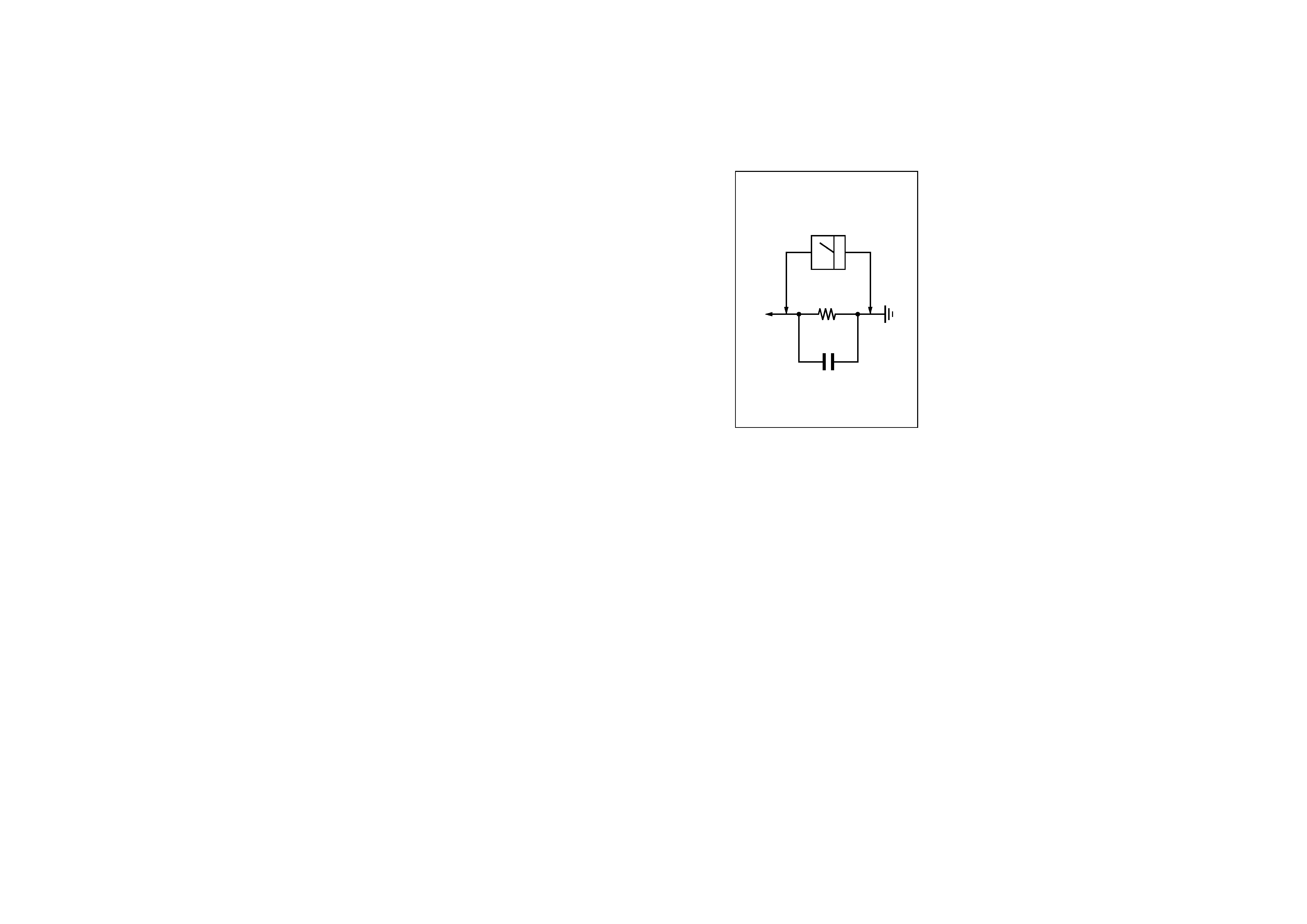
are suitable. (See Fig. A)
Fig. A. Using an AC voltmeter to check AC leakage.
1.5 k
0.15 µF
AC
Voltmeter
(0.75 V)
To Exposed Metal
Parts on Set
Earth Ground
SAFETY CHECK-OUT
After correcting the original service problem, perform the following safety
checks before releasing the set to the customer:
1. Check the area of your repair for unsoldered or poorly-soldered
connections. Check the entire board surface for solder splashes and
bridges.
2. Check the interboard wiring to ensure that no wires are "pinched" or
contact high-wattage resistors.
3. Check that all control knobs, shields, covers, ground straps, and
mounting hardware have been replaced. Be absolutely certain that you
have replaced all the insulators.
4. Look for unauthorized replacement parts, particularly transistors, that
were installed during a previous repair. Point them out to the customer
and recommend their replacement.
5. Look for parts which, though functioning, show obvious signs of
deterioration. Point them out to the customer and recommend their
replacement.
6. Check the line cords for cracks and abrasion. Recommend the
replacement of any such line cord to the customer.
7. Check the connector shell, metal trim, "metallized" knobs, screws, and
all other exposed metal parts for AC Leakage. Check leakage as de-
scribed right.