
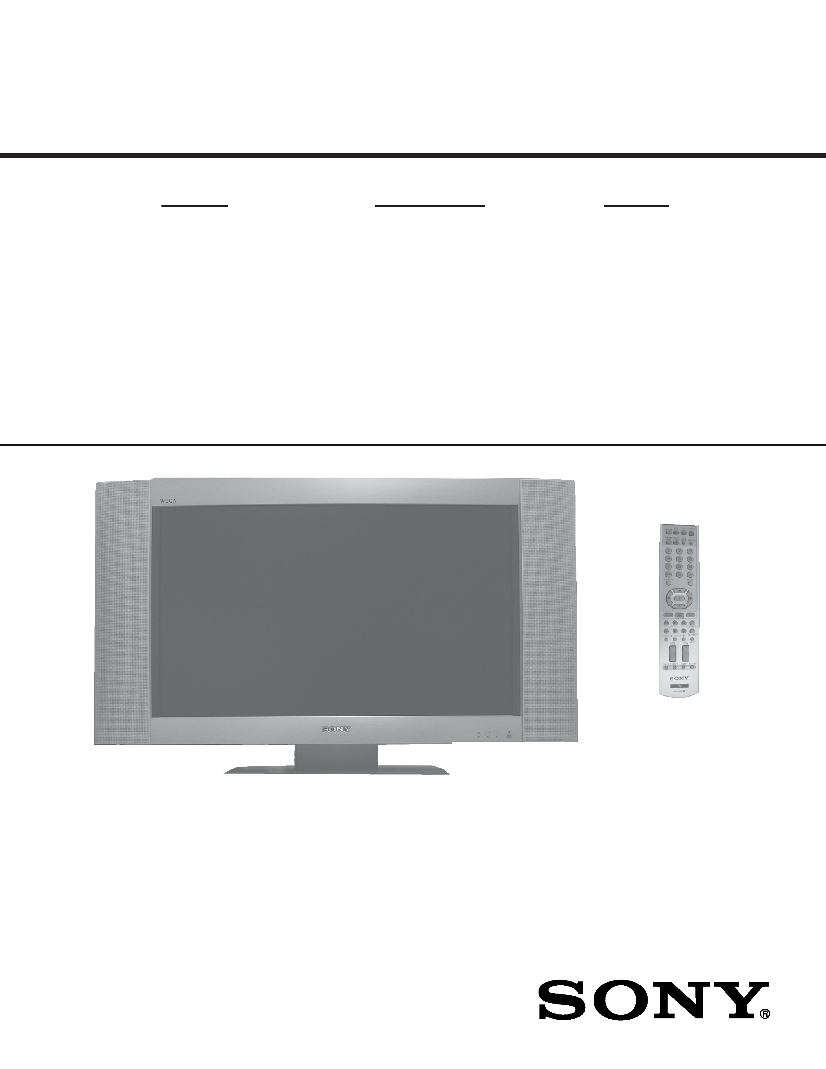
LCD COLOR TV
SERVICE MANUAL
AT2
CHASSIS
MODEL NAME
REMOTE COMMANDER
DESTINATION
9-965-976-02
KLV-26HG2
RM-Y1105
US/CND
(This manual is for units within S/N Range: 8,100,000 - 9,100,000 Only)
HISTORY INFORMATION FOR THE FOLLOWING MANUAL:
ORIGINAL MANUAL ISSUE DATE: 9/2004
:UPDATED ITEM
REVISION DATE
SUBJECT
9/2004
No revisions or updates are applicable at this time.
2/2005
Added Caution statement (Replaced Page 5 with Page 5)
LCD COLOR TV
SERVICE MANUAL
AT2
CHASSIS
MODEL NAME
REMOTE COMMANDER
DESTINATION
9-965-976-02
KLV-26HG2
RM-Y1105
US/CND
(This manual is for units within S/N Range: 8,100,000 - 9,100,000 Only)
KLV-26HG2
RM-Y1105

KLV-26HG2
KLV-26HG2
3
TABLE OF CONTENTS
SECTION TITLE
PAGE
SECTION TITLE
PAGE
Specifications ................................................................................. 4
Warnings and Cautions .................................................................. 5
Safety Check-Out ........................................................................... 6
SECTION 1: DISASSEMBLY................................................................. 7
1-1. Rear Cover and Stand Removal ............................................ 7
1-2. Cabinet Assembly Removal ................................................... 7
1-3. U1 Board Removal................................................................. 8
1-4. MS and MSB Board Removal ................................................ 8
1-5. G1 Board Removal................................................................. 9
1-6. A1, TU and UD Board Removal ............................................. 9
1-7. B Board Removal ................................................................. 10
1-8. H1 and MSX Board Removal ............................................... 10
1-9. H2 Board Removal................................................................11
1-10. H3 Board Removal...............................................................11
SECTION 2: ADJUSTMENTS ............................................................. 12
2-1. Setting the Service Adjustment Mode .................................. 12
2-2. White Balance Adjustments ................................................. 12
SECTION 3: DIAGRAMS..................................................................... 13
3-1. Circuit Boards Location ........................................................ 13
3-2. Printed Wiring Boards and
Schematic Diagrams Information ......................................... 14
3-3. Block Diagrams (1 of 6)........................................................ 15
Block Diagrams (2 of 6)........................................................ 16
Block Diagrams (3 of 6)........................................................ 17
Block Diagrams (4 of 6)........................................................ 18
Block Diagrams (5 of 6)........................................................ 19
Block Diagrams (6 of 6)........................................................ 20
3-4. Frame Diagrams ................................................................. 21
3-5. Schematics and Supporting Information ............................. 22
A1 Board Schematic Diagram (1 of 4).................................. 22
A1 Board Schematic Diagram (2 of 4).................................. 23
A1 Board Schematic Diagram (3 of 4).................................. 24
A1 Board Schematic Diagram (4 of 4).................................. 25
TU Board Schematic Diagram ............................................ 27
B Board Schematic Diagram (1 of 8) ................................... 28
B Board Schematic Diagram (2 of 8) ................................... 29
B Board Schematic Diagram (3 of 8) ................................... 30
B Board Schematic Diagram (4 of 8) ................................... 31
B Board Schematic Diagram (5 of 8) ................................... 32
B Board Schematic Diagram (6 of 8) ................................... 33
B Board Schematic Diagram (7 of 8) ................................... 34
B Board Schematic Diagram (8 of 8) ................................... 35
UD Board Schematic Diagram ............................................ 37
H1 Board Schematic Diagram ............................................. 39
H2 Board Schematic Diagram ............................................. 39
H3 Board Schematic Diagram ............................................. 40
U1 Board Schematic Diagram ............................................. 40
MS Board Schematic Diagram (1 of 3) ................................ 41
MS Board Schematic Diagram (2 of 3) ................................ 42
MS Board Schematic Diagram (3 of 3) ................................ 43
MSB Board Schematic Diagram ......................................... 45
MSX Board Schematic Diagram ......................................... 45
G1 Board Schematic Diagram ............................................ 46
3-6. Semiconductors ................................................................... 48
SECTION 4: EXPLODED VIEWS ........................................................ 49
4-1. Cabinet Assembly and Stand Assembly............................... 49
4-2. Chassis ................................................................................ 50
4-3. Packing Materials................................................................. 51
SECTION 5: ELECTRICAL PARTS LIST........................................... 52

KLV-26HG2
KLV-26HG2
4
SPECIFICATIONS
Television system:
American TV Standard
Channel coverage:
VHF: 2-13/ UHF: 14-69/ CATV: 1-125
Antenna:
75-ohm external antenna terminal for VHF/UHF
Screen Size (measured diagonally):
26 inches
Panel System:
a-Si TFT Active Matrix LCD Panel
(Effective dots: more than 99.99%)
Display Resolution:
1280 dots (horizontal) x 768 lines (vertical)
Video 1/2 In:
S VIDEO IN (4-pin mini DIN):
Y: 1 Vp-p, 75 ohms unbalanced, sync negative
C: 0.286 Vp-p (Burst signal), 75ohms
VIDEO:
1 Vp-p, 75ohms unbalanced, sync negative
AUDIO:
500 mVrms (100% modulation)
Impedance:47 kilohms
Video 3 In:
Y, PB, PR (Component Video) IN:
Y: 1.0 Vp-p, 75 ohms unbalanced, sync negative
PB: 0.7 Vp-p, 75 ohms
PR: 0.7 Vp-p, 75 ohms
Signal formal:
480i, 480p, 720p, 1080i
AUDIO:
500 mVrms (100% modulation)
Impedance:47 kilohms
Video 4 In:
DVI-HDTV:
1 terminal, 3.3V T.M.D.S., 50 ohms
The DVI-HDTV input terminal is compliant with
the EIA-861B standard and is not intended for use
with personal computers.
AUDIO:
500 mVrms (100% modulation)
Impedance:47 kilohms
Audio Out:
500 mVrms (100% modulation)
More than 500 mVrms at the maximum volume setting (Variable)
More than 500 mVrms (Fixed)
Headphones:
Stereo Minijack
Impedance: 16ohms
Speaker:
Full Range: 4.0 x 10.0 cm Oval
(1
9/16 x 3 15/16 inches) (2)
Tweeter: 2.5 cm (31/32 inches) (2)
Speaker Output:
4.0 W x 4.0 W
Power Requirements:
120V AC, 60 Hz
Power Consumption:
In use:
134W
In Standby:
Less than 1W
Dimensions (W/H/D):
Including TV Stand and Rear Cover:
790 x 490 x 240 mm
(31 3/32 x 19 9/32 x 9 7/16 inches)
Without TV Stand and Rear Cover:
790 x 430 x 138 mm
(31
3/32 x 16 15/16 x 5 7/16 inches)
Mass:
Including TV Stand and Rear Cover:
18.4 kg (40 lbs. 8 ozs.)
Without TV Stand and Rear Cover:
15.2 kg (33 lbs. 8 ozs.)
Supplied Accessories
Remote Commander RM-Y1105 (1)
Two Size AA Batteries
75-ohm coaxial cable (1)
AC power Cord (1)
Rear Cover (1)
Operating Instructions
Warranty Card
Product Registration
Optional Accessories
Note that some optional accessories may be out of stock.
Headphones Plug Adaptor
Connecting Cables
"Memory Stick" Media
Wall-Mount Bracket SU-LW1
Design and specifications are subject to change without notice.

KLV-26HG2
KLV-26HG2
5
CAUTION
These servicing instructions are for use by qualified service personnel only. To reduce the risk of electric shock, do not perform any
servicing other than that contained in the operating instructions unless you are qualified to do so.
WARNING!!
An isolation transformer should be used during any service to avoid possible shock hazard, because of live chassis. The chassis of
this receiver is directly connected to the ac power line.
! SAFETY-RELATED COMPONENT WARNING!!
Components identified by shading and ! mark on the schematic diagrams, exploded views, and in the parts list are critical for safe
operation. Replace these components with Sony parts whose part numbers appear as shown in this manual or in supplements
published by Sony. Circuit adjustments that are critical for safe operation are identified in this manual. Follow these procedures
whenever critical components are replaced or improper operation is suspected.
ATTENTION!!
Ces instructions de service sont à l'usage du personnel de service qualifié seulement. Pour prévenir le risque de choc électrique, ne
pas faire l'entretien autre que celui contenu dans le Mode d'emploi à moins que vous soyez qualifié faire ainsi.
Afin d'eviter tout risque d'electrocution provenant d'un chássis sous tension, un transformateur d'isolement doit etre utilisé lors de tout
dépannage. Le chássis de ce récepteur est directement raccordé à l'alimentation du secteur.
! ATTENTION AUX COMPOSANTS RELATIFS A LA SECURITE!!
Les composants identifies par une trame et par une marque ! sur les schemas de principe, les vues explosees et les listes de pieces
sont d'une importance critique pour la securite du fonctionnement. Ne les remplacer que par des composants Sony dont le numero
de piece est indique dans le present manuel ou dans des supplements publies par Sony. Les reglages de circuit dont l'importance
est critique pour la securite du fonctionnement sont identifies dans le present manuel. Suivre ces procedures lors de chaque
remplacement de composants critiques, ou lorsqu'un mauvais fonctionnement suspecte..
WARNINGS AND CAUTIONS