CHASSIS
LE-1
37
Please file according to model size. ....
TRINITRON® COLOR TV
KL-37W2U
RM-838
UK
MODEL
COMMANDER
DEST.
MODEL
COMMANDER
DEST.
MICROFILM
SERVICE MANUAL

2
Specifications
This product complies with the EU Directive 89/336/EEC.
Sound output
2
× 5 W (RMS)
Centre 1
× 20 W
Power consumption
170W
Dimensions (W
× H × D) Approx. 920 × 825 × 390 mm
Weight
Approx. 29 kg
Supplied accessories
See page 6.
Other features
Digital comb filter (High resolution)
PAP (Picture-and-picture)
FASTEXT
Graphic Equalizer
Design and specifications are subject to change without notice.
Receivable Channels and Channel Displays
Television system
B/G/H, D/K, I, L
Colour system
NTSC 3.58/4.43 (VIDEO IN)
Channel coverage
See "Receivable channels and
channel displays" at the bottom.
Projected picture size
37 inches
Approx. 94 cm diagonally
Terminals
Rear
1 21-pin Euro connector
(CENELEC standard) inputs for audio
and video signals
- inputs for RGB
- outputs of TV video and audio
signals
2/
S
2 21-pin Euro connector
- inputs for audio and video signals
- inputs for S video
- outputs for audio and video signals
(selectable)
4/
S
4 21-pin Euro connector
- inputs for audio and video signals
- inputs for S video
- outputs for audio and video signals
(monitor out)
S
2,
S
4 S video inputs
- 4 pin DIN
Audio inputs (L, R) - phono jacks
S
S video output 4-pin DIN
Audio outputs - phono jacks
Audio outputs (variable)-phono
jacks
Front
3 video input - phono jack
Audio inputs - phono jacks
S
3 S video input - 4-pin DIN
2 Headphone jack: stereo minijack
B/G/H
CABLE TV (1)
CABLE TV (2)
ITALY
D/K
CABLE TV (1)
CABLE TV (2)
CABLE TV
L
I
Indication on the
screen
C02 C03 C04..C12
C21..C69
S01 S02..S41
S42..S46 S01..S10
S11..S20
C11..C69
C02..C12 C21..C69
S01 S02..S41
S42 S43..S46
S02, S03..S17,
S21..S41
C01..C12 C21..C69
C21..C68
Receivable
channels
E2..12 21..69
S1..41
S01..S05 M1..M10
U1..U10
A B C D E F G H H1
H2 21..69
R01..R12 R21..R69
B..Q, S21..41
F2..F10 F21..F69
B21..B68

3
TABLE OF CONTENTS
Section
Title
Page
Section
Title
Page
1. GENERAL ...................................................
4
2. DISASSEMBLY
2-1.
Rear Cover Removal ........................................
18
2-2.
Chassis Assy Removal .....................................
18
2-3.
Service Position ................................................
18
2-4.
F2 Board and F2 Bracket Removal ..................
18
2-5.
BB, B1 and J Boards Removal .........................
19
2-6
Power Block Removal ......................................
19
2-7.
Filter Removal ..................................................
19
2-8.
Lamp Removal .................................................
20
2-9.
H and F1 Boards Removal ...............................
20
2-10.
Screen Frame Removal ....................................
20
2-11.
C Board Removal .............................................
21
2-12.
Optical Unit Removal .......................................
21
3. CIRCUIT ADJUSTMENTS
3-1.
Electrical Adjustments .....................................
22
3-2.
Test Mode .........................................................
24
3-3.
Error Monitor and Detection ............................
26
3-4.
Registration Adjustment ...................................
27
3-5.
C Board Adjustment .........................................
27
3-6.
A Board Adjustment .........................................
30
3-7.
Sub BRT, Sub PIX Adjsutment .......................
30
3-8.
White Balance Adjustment ..............................
30
4. DIAGRAMS
4-1.
Block Diagrams ................................................
33
4-2.
Frame Schematic Diagram ...............................
42
4-3.
Circuit Boards Location ...................................
44
4-4.
Schematic Diagrams and Printed
Wiring Boards ..............................................
44
(1)
Schematic Diagrams of F1, F2,
G, H, J, TA and TB Boards ............................
45
(2)
Schematic Diagram of A (1/3) Board .................
55
(3)
Schematic Diagram of A (2/3) Board .................
59
(4)
Schematic Diagram of A (3/3) Board .................
61
(5)
Schematic Diagram of B1 (1/3) Board ...............
63
(6)
Schematic Diagram of B1 (2/3) Board ...............
66
(7)
Schematic Diagram of B1 (3/3) Board ...............
69
(8)
Schematic Diagram of C (1/2) Board .................
73
(9)
Schematic Diagram of C (2/2) Board .................
77
(10) Schematic Diagram of BB (1/3) Board ..............
80
(11) Schematic Diagram of BB (2/3) Board ..............
83
(12) Schematic Diagram of BB (3/3) Board ..............
86
4-5.
Semiconductiors ...............................................
88
5. EXPLODED VIEWS
5-1.
Chassis ..............................................................
90
5-2.
Front Cover .......................................................
91
5-3.
Screen Mirror Block and Optics Unit ..............
92
6. ELECTRICAL PARTS LIST ..........................
93
SAFETY-RELATED COMPONENT WARNING!!
COMPONENTS IDENTIFIED BY SHADING AND MARK
! ON THE SCHEMATIC DIAGRAMS, EXPLODED
VIEWS AND IN THE PARTS LIST ARE CRITICAL TO
SAFE OPERATION. REPLACE THESE COMPONENTS
WITH SONY PARTS WHOSE PART NUMBERS APPEAR
AS SHOWN IN THIS MANUAL OR IN SUPPLEMENTS
PUBLISHED BY SONY.
4
SECTION 1
GENERAL
The operating instructions mentioned here are partial abstracts
from the Operating Instruction Manual. The page numbers of
the Operating Instruction Manual remein as in the manual.
4
Name
Main power switch
Standby indicator
Stereo A/B indicators
Programme
Volume buttons
Input select buttons
Headphones jack
Input jacks (S video/video/audio)
Symbol
f
f
A- m -B
PROGR+/
+/
l
S
3,
3,
3
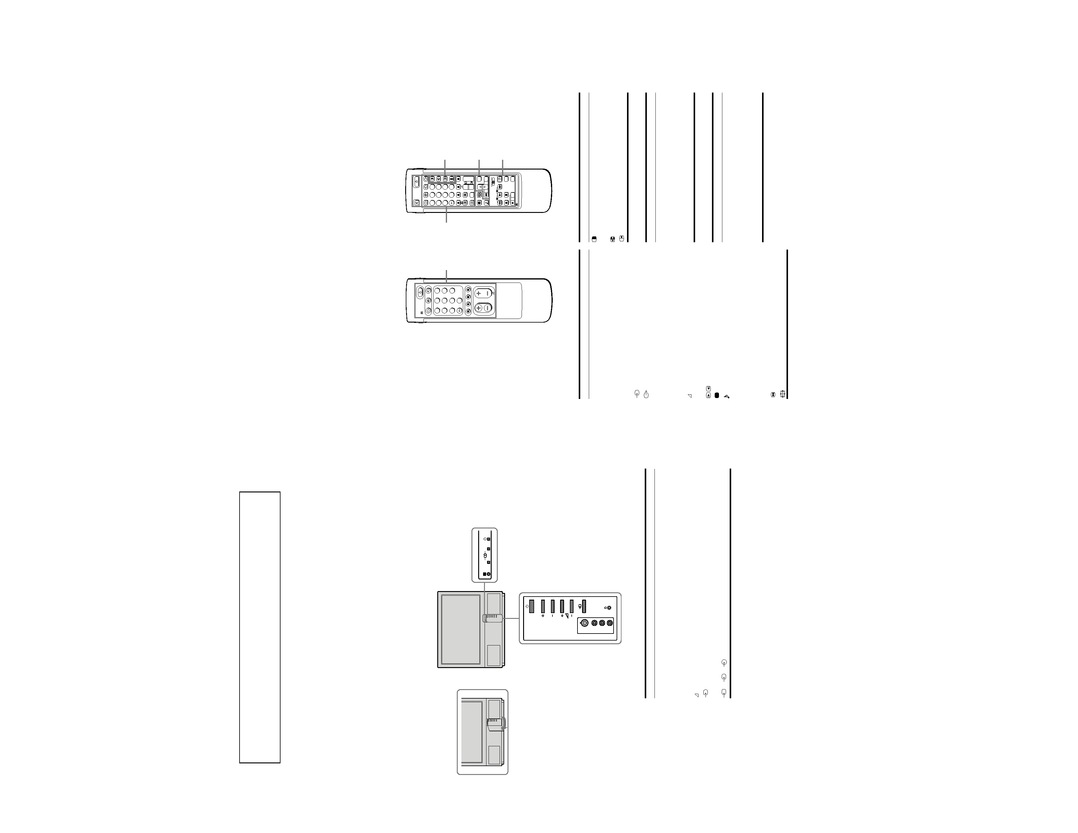
Overview
This section briefly describes the buttons and controls on the TV
set and on the Remote Commander. For more information, refer to
the pages given next to each description.
TV set-front
Refer to page
14
14
16
14
14
15
23
24
AB
PROGR
5
Name
PAP on/off button
PAP source selector
Swap button
PAP freeze button
Name
Menu on/off button
Select buttons
OK(confirming)button
Back button
Remote commander
TV/Teletext
operation
Full-Function side
Simple side
Note
The SAT button does not
operate with this TV.
PAP (Picture-and-picture) operation
Menu operation
Refer to page
7
7
7
7
Symbol
VTR1/2/3,
MDP
;; - ::
L
J a f
PROGR +/
Name
Video equipment selector
Video equipment operation
buttons
Refer to page
26
26
Video operation
PAP operation
Menu operation
Video operation
Name
Mute on/off button
Standby button
TV power on/TV mode selector
button
Teletext button
Input mode selector
Output mode selector
Number buttons
Double-digit entering button
Direct channel entering button
Volume control button
Programme selectors
Teletext page access buttons
Picture adjustment button
Sound adjustment button
On-screen display button
Teletext hold button
Time display button
Fastext buttons
"Freeze" button
Button to change Screen Format
Refer to page
15
14
14
15
15
24
14
14
10
14
14
20
16
16
15
20
15
20
15
15
1 1
$
Symbol
o
f
O
_
1,2,3,4,5,6,
7,8,9 and 0
/--
C
+/
PROGR +/
[
#
LLLL
TV/Teletext operation
Refer to page
18
18
18
18
Symbol
C
Symbol
MENU
>
+/ ?
OK
@
PROGR
RM-838
1
2
45
3
6
9
8
7
0
PROGR
PROGR
1
1
VTR 1-2-3 MDP
1
2
45
3
6
9
8
7
0
C
SAT
+
+
_
_
MENU
+
_
OK
+
_
RM-838
USE
MEM
RESET
5
6
R/D/D/D
L/G/S/I
R/D/D/D
L/G/S/I
R/D/D/D
L/G/S/I
R/D/D/D
L/G/S/I
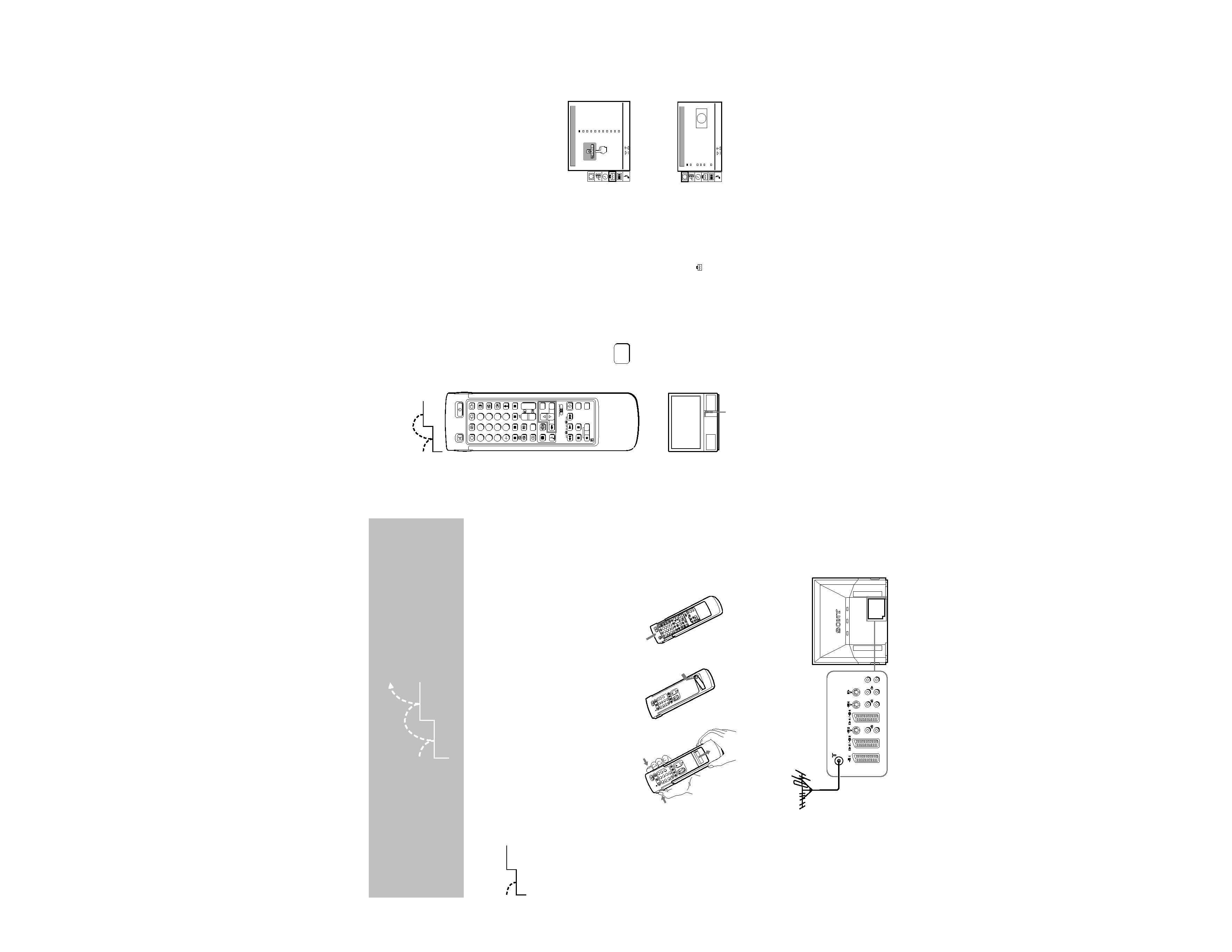
Check the supplied accessories
When you've taken everything
out of the carton, check that you
have these items:
·
RM-838 Remote Commander
·
One IEC designation R6 battery
·
Wrench (1)
·
Bracket (2)
·
Dust Remover (1)
Insert the battery into the Remote Commander
Step 1 Preparation
Getting Started
1
Fit an IEC aerial connector attached to 75-ohm coaxial cable (not
supplied) to the ) socket at the rear of the TV.
RM-838
PROGR
VTR
1-2-3
MDP
1
2
4
5
3
6
9
8
7
0
C
SAT
MENU
+
_
OK
+
4
PROGR
1
1
+
_
+
_
3
PROGR
8
7
0
9
RM-838
5
3
2
4
6
1
1
1
2
PROGR
RM-838
8
7
0
5
3
2
4
6
9
1
Remove the cover.
Check the correct
polarities.
Refit the outside cover
making sure that the Full-
Function side is visible to use
the menu in step 2.
Note: Always remember
to dispose of used
batteries in an
enviromental friendly
way.
2
3
3 Connect the aerial
1
2
1
2
7
PROGR
PROGR
1
1
VTR 1-2-3 MDP
1
2
45
3
6
9
8
7
0
C
SAT
+
+
_
_
MENU
+
_
OK
+
_
RM-838
USE
MEM
RESET
Step 2 Tuning in to TV Stations
Once you have set up the TV, you can choose the language of the
menu. Then, you should preset the channels (up to 100 channels)
by choosing either the automatic or manual method. The
automatic method is easier if you want to preset all receivable
channels at once. Use the manual method if you only have a few
channels and want to preset channels one by one.
Before you begin
·
Check that the Full-Function side of the Remote Commander is
visible.
·
Locate Menu operation buttons on the Remote Commander.
They are shaded in the illustration at the left.
Choose a language
1
Press f on the TV.
The TV will switch on. If the standby indicator on the TV is lit, press
O
or a number button on the Remote Commander.
2
Press the MENU button.
The LANGUAGE menu appears. (See Fig. 1.)
3
Select the language you want with > + or ? and press OK.
Display the menu
Press MENU.
The main menu appears. (See Fig. 2.)
Using > + or ? select the symbol
and press OK.
Now, choose one of the methods described overleaf:
"Preset Channels Automatically"
or
"Preset Channels Manually"
MENU
To go back to main
menu
Keep pressing @.
To go back to the
normal TV picture
Press MENU. Normal
TV picture will be
restored after one
minute if menu functions
are not selected.
Note on the Demo
function
If you choose Demo in
the Installation menu,
you can see a sequential
demonstration of the
menu functions.
Press MENU to stop the
function.
1
2
1
2
f
Fig. 2
Fig. 1
Auto 16:9
Select
and press OK
Clip Board
PAP
Strobe
Screen Position
Screen Mode
[off]
[off]
[on]
[
]
[
]
zoom
0
SCREEN MODE
LANGUAGE
English
Deutsch
Français
Italiano
Español
Nederlands
Português
Suomi
Svenska
E
LvØxÆ
Türkçe
Select
and press OK
Select
+
_
OK