CHASSIS
LE-3
SERVICE MANUAL
MODEL
COMMANDER
DEST. CHASSIS NO.
MODEL
COMMANDER
DEST. CHASSIS NO.
50
Please file according to model size. .......
LCD PROJECTION TV
KF-50SX100
RM-903
AEP
SCC-P59A-A
KF-50SX100K RM-903
OIRT
SCC-P60A-A
KF-50SX100U RM-903
UK
SCC-P61A-A
KF-50SX100/50SX100K/50SX100U
RM-903
RM 903
PROGR
MENU
1
4
7
2
5
8
0
3
6
9
VIDEO
TV
SONY
OK
TV
2
RM-903
RM-903
RM-903
KF-50SX100/50SX100K/50SX100U
SPECIFICATIONS
RM-903
RM-903
RM-903
3
KF-50SX100/50SX100K/50SX100U
SELF DIAGNOSIS FUNCTION
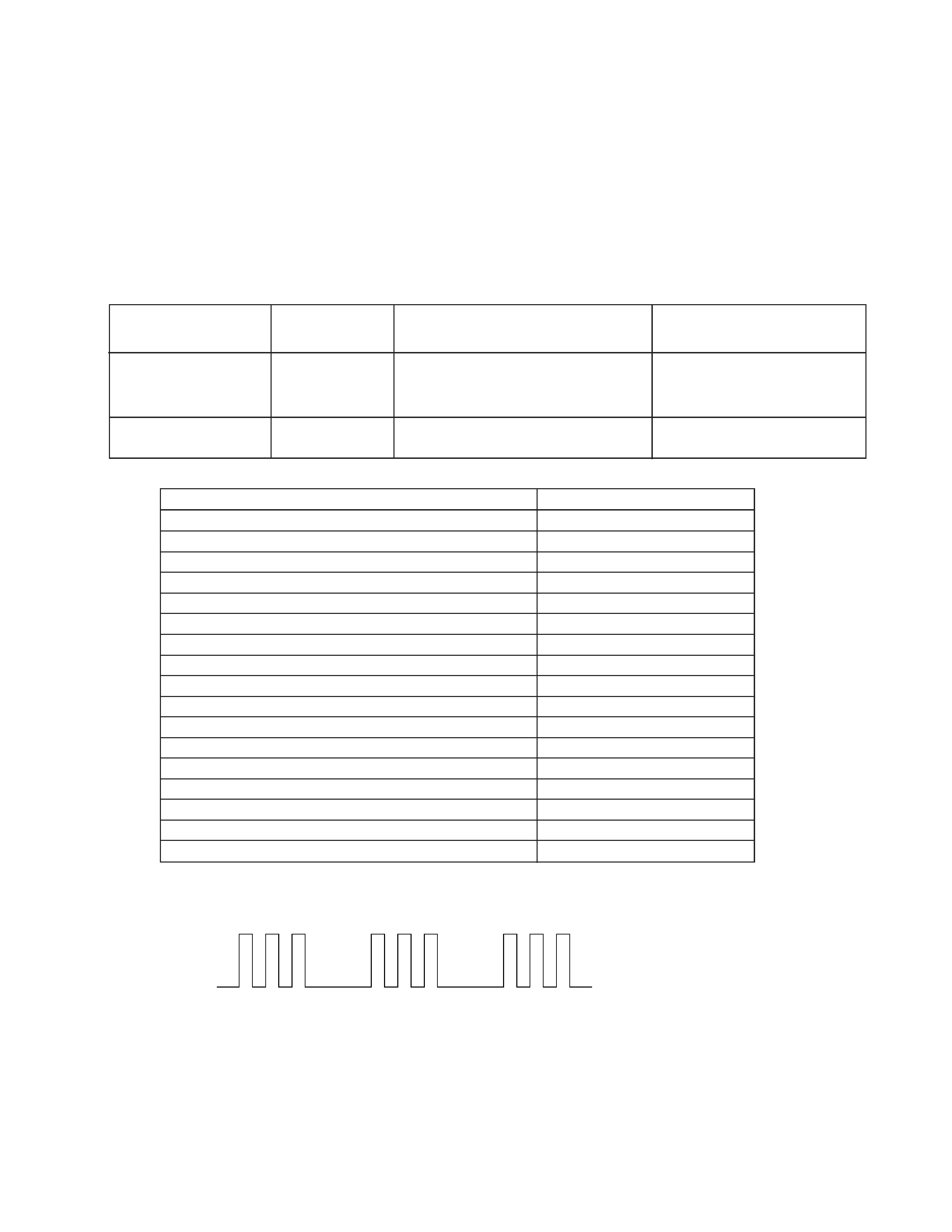
1-1. LE-3 SELF DIAGNOSTIC SOFTWARE
The identification of errors within the LE-3 chassis is triggered in one of two ways : - 1: Busy or 2: Device failure to respond to IIC. In
the event of one of these situations arising the software will first try to release the bus if busy (Failure to do so will report with
continuous flashing LED) and then communicate with each device in turn to establish if a device is faulty. If a device is found to be
faulty the relevant device number will be displayed through the LED (Series of flashes which must be counted) See table 1., non fatal
errors are reported using this method.
Power cord is not plugged in
Power does not come on
Power does not turn on
Does not light
Fuse is Burned out
No power is supplied to the TV
AC power supply is faulty
SET 5V Dowin
2 times
Q1606, 1607 Power FET is shorted
Power does not come on
(G Board)
Load on power line has shorted
No. of times Standby
LED Flashes
Detected Symptoms
ERROR
STBY LED ERROR COUNT
No error
00
Not allowed (may be confused with Sircs response flash)
01
SET 5V Down
02
Lamp Cover error
03
Fan error
04
Lamp Driver error
05
Not used
06
Speaker Protection
07
General IIC Line 0 error
08
MEGATEXT (IC9502)
09
NVM (IC9108)
10
Main colour decoder (IC8301)
11
MCP (IC701)
14
Multi sound processor (IC4702)
15
Auto Wide (IC8700)
16
External RAM (IC9107)
17
Lamp error
Lamp LED continnously on
Diagnostic Item
Description
Probable cause Location
Flash Timing Example : e.g. error number 3
ON
OFF
OFF
ON
ON
Standby LED

4
RM-903
RM-903
RM-903
KF-50SX100/50SX100K/50SX100U
1-2. ERROR DETECTION MONITOR
Device acknowledge is used to check IIC errors.
Each device is checked three times, if there is no acknowledge after every attempt, it will be regarded as an error.
There are three step to check errors.
1. IIC line 0
If all devices except the NVM have errors, IIC line 0 error is displayed.
2. Each device check
if IIC line error and board error are not detected then the device with an error is displayed.
The detected errors can be displayed as follows:
1. Error Monitor Menu
2. Error Reader
1-2-1. Error Monitor Menu
The error monitor menu is displayed by selecting Service mode : Monittoring. The following menu will be displayed:
Error Monitor
1
Operating Time :
Stored Errors :
1. J-B MSP3410
Current Error :
Start Error Sequence
2. B3-B CXA2101 MCP
3. J-B CXA2123 Main Col Dec
4. Error Code Not Valid
5. Error Code Not Valid
Ignore Errors
OFF
000021 h 40 min
ON
ON
Error Monitor
1
LAMP
: 0
5
LAMP DRIVER
: 0
4FAM
: 0
3
LAMP COVER
: 1
WDT-E
: 0
Error Monittor
LCD-Engine error menu
RM-903
RM-903
RM-903
5
KF-50SX100/50SX100K/50SX100U
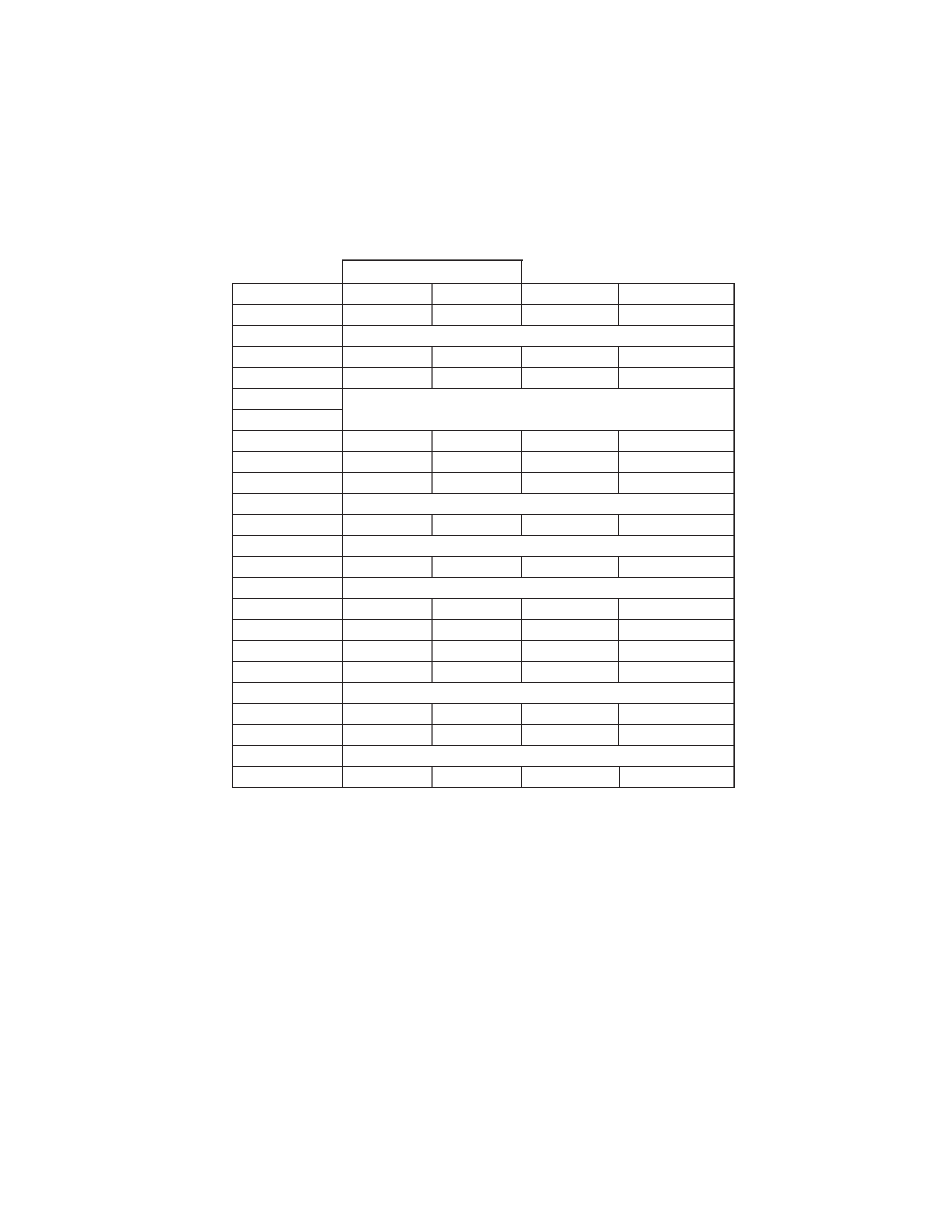
1-2-2. Error Reader Display
The error reader display is connected to the service connector to read actual error codes. The part number for the error reader display is
S-188-900-10.
Once an error has been detected it will then be displayed on the two digit error reader. The errors displayed refer to the following table:
Send Data to Error Reader
Error Code
Data High
Data Low
Error Type
Function
00 00h
f0h
no device
Gen. IIC Error
00 01h
f0h
01h
IIC 0 line
00 02h
f0h
02h
IIC 1 line
not used
Device Error
A Board
01 01h
f1h
01h
CXA1875
Port Expander
01 02h
f1h
02h
TU1301
Main Tuner
01 03h
f1h
03h
TU1302
Sub Tuner
BB Board
04 01h
f4h
01h
CXD9509
MID-X
BB Board
06 01h
f6h
01h
CXA2101
MCP
J Board
04 04h
f4h
04h
TDA9178
Picture Booster
07 03h
f7h
03h
CXA2123
Sub Colour
07 04h
f7h
04h
CXA2123
Main Colour
07 0Ah
f7h
0Ah
CXA2149
AV SW
S Board
07 05h
f7h
05h
CXA1875
Sub Sound
07 08h
f7h
08h
MSP3410D
Sound Proc
M Board
08 01h
f8h
01h
ST24C32
NVM