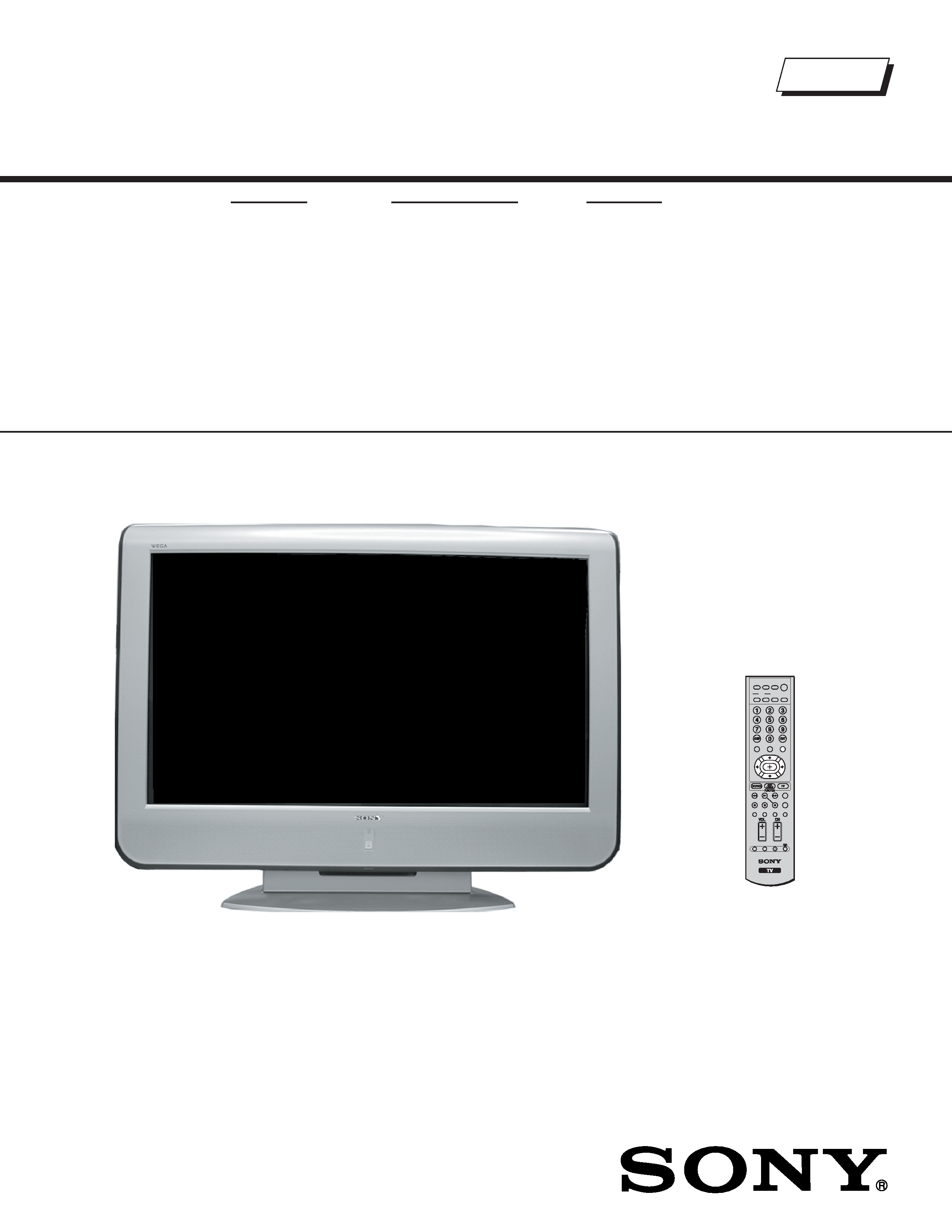
FLAT PANEL COLOR TELEVISION
SERVICE MANUAL
AT-2 CHASSIS
MODEL NAME
REMOTE COMMANDER
DESTINATION
9-965-967-03
KE-42M1
RM-Y1003
US
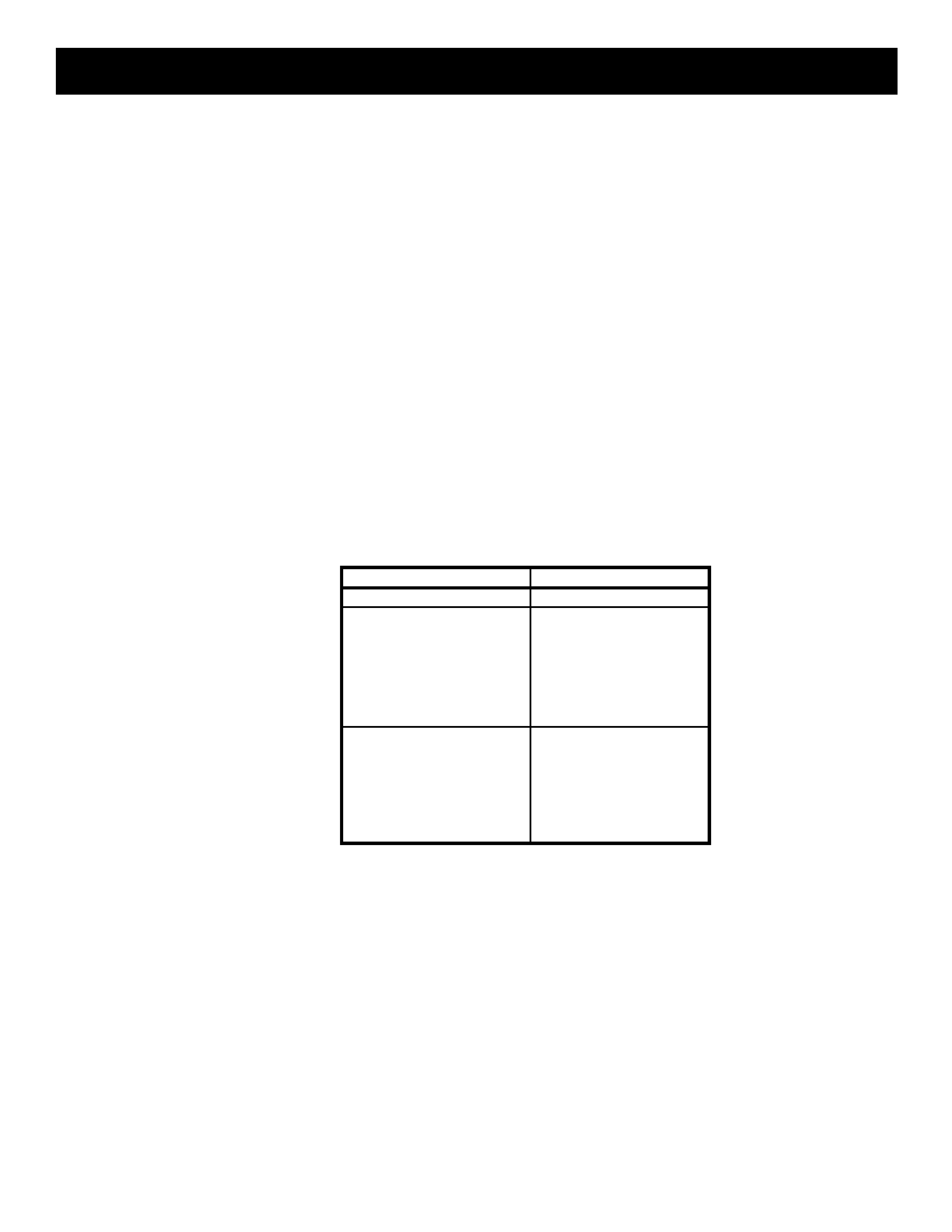
HISTORY INFORMATION FOR THE FOLLOWING MANUAL:
ORIGINAL MANUAL ISSUE DATE: 6/2004
:UPDATED ITEM
REVISION DATE
SUBJECT
6/2004
No revisions or updates are applicable at this time.
7/2004
Corrected PN for PDP Module Assembly (Replaced page 53 with page 53)
Added Battery Cover PN (Replaced page 93 with page 93)
1/2005
Added Caution statement (Replaced Page 5 with Page 5)
FLAT PANEL COLOR TELEVISION
SERVICE MANUAL
AT-2 CHASSIS
MODEL NAME
REMOTE COMMANDER
DESTINATION
9-965-967-03
KE-42M1
RM-Y1003
US
Self Diagnosis
Supported model
KE-42M1
MUTING
PICTURE WIDE
FAVORITES
TV VIDEO 1/2/3 VIDEO 4 VIDEO 5
F1
F2
MENU
SLEEP DISPLAY
MODE
SAT/
CABLE
POWER
FREEZE
TOP MENU
RESET PIC OFF MTS/SAP
GUIDE
TV/SAT
DVD/
VCR
RM-Y1003

3
KE-42M1
KE-42M1
TABLE OF CONTENTS
SECTION TITLE
PAGE
SECTION TITLE
PAGE
Specifications ................................................................................. 4
Warnings and Cautions .................................................................. 5
Safety Check-Out ........................................................................... 6
Self-Diagnostic Function................................................................. 7
SECTION 1: DISASSEMBLY................................................................. 8
1-1. Stand and Rear Cover Removal ............................................ 8
1-2. Main Shield Removal ............................................................. 9
1-3. P Board and UPU Board Removal......................................... 9
1-4. AU Board and BP Board Removal ....................................... 10
1-5. F Board and G2 Board Removal.......................................... 10
1-6. G1 Board Removal............................................................... 11
1-7. LCD Panel Removal............................................................. 12
1-8. H1 Board and H3 Board Removal........................................ 13
1-9. H2 Board Removal............................................................... 13
SECTION 2: ADJUSTMENTS ............................................................. 14
2-1. White Balance Adjustments ................................................. 14
2-2. Resetting Data ..................................................................... 14
2-3. Aging Mode .......................................................................... 14
2-4. Panel Voltage Adjustment .................................................... 15
2-5. Remote Adjustment Buttons and Indicators ......................... 15
SECTION 3: DIAGRAMS..................................................................... 16
3-1. Circuit Boards Location ........................................................ 16
3-2. Printed Wiring Boards and Schematic Diagrams Information17
3-3. Block Diagrams .................................................................... 18
3-4. Schematics and Supporting Information .............................. 19
G1 Board Schematic Diagram ............................................. 19
G2 Board Schematic Diagram ............................................. 20
UPU Board Schematic Diagram (1 of 2) .............................. 23
UPU Board Schematic Diagram (2 of 2) .............................. 24
BP Board Schematic Diagram (1 of 6) ................................. 27
BP Board Schematic Diagram (2 of 6) ................................. 28
BP Board Schematic Diagram (3 of 6) ................................. 29
BP Board Schematic Diagram (4 of 6) ................................. 30
BP Board Schematic Diagram (5 of 6) ................................. 31
BP Board Schematic Diagram (6 of 6) ................................. 32
F Board Schematic Diagram ................................................ 35
AU Board Schematic Diagram (1 of 4)................................. 38
AU Board Schematic Diagram (2 of 4)................................. 39
AU Board Schematic Diagram (3 of 4)................................. 40
AU Board Schematic Diagram (4 of 4)................................. 41
P Board Schematic Diagram................................................ 44
H1 Board Schematic Diagram.............................................. 45
H2 Board Schematic Diagram.............................................. 46
H3 Board Schematic Diagram.............................................. 47
3-5. Semiconductors ................................................................... 49
SECTION 4: EXPLODED VIEWS ........................................................ 50
4-1. Rear Cover and Stand ......................................................... 50
4-2. Chassis ................................................................................ 51
4-3. Front Panel........................................................................... 52
4-4. Bezel Assembly.................................................................... 53
4-5. Packing Material................................................................... 54
SECTION 5: ELECTRICAL PARTS LIST........................................... 55
4
KE-42M1
KE-42M1
SPECIFICATIONS
Design and specifications are subject to change without notice.
120V AC, 60Hz
370W
Under 1 W
VIDEO
Video
1Vp-p, 75ohms unbalanced, sync negative
S Video
(4-pin mini DIN)
Y: 1Vp-p, 75ohms unbalanced, sync negative
C: 0.286Vp-p (Burst signal), 75ohms
Audio
500 mVrms (100% modulation)
Impedance:47 kilo ohms
HD/DVD IN
Y, PB, PR (Component Video)
Y: 1.0 Vp-p, 75 ohms unbalanced, sync negative
PB
: 0.7 Vp-p, 75 ohms;
PR: 0.7 Vp-p, 75 ohms
Signal Format 480i, 480p, 720p, 1080i
Audio
500 mVrms at (100% modulation)
Impedance:47 kilo ohms
Power Requirements
Power Consumption (W)
In Use (Max)
In Standby
Inputs/Outputs
HDMI IN
HDMI IN
Video: 1080i, 720p, 480p, 480i
Audio: Twho channel linear PCM32, 44.1, and 48 kHz
16, 20, and 24 bits
Audio
500 mVrms at (100% modulation)
Impedance:47 kilo ohms
AUDIO OUT
500 mVrms at (100% modulation)
More than 1 Vrms at the maximum volume setting (Variable)
More than 500 mVrms (Fixed)
Headphones
Stereo mini jack
Impedance: 16 ohms
Television system
American TV standard, NTSC
Channel coverage
VHF: 2-13/ UHF: 14-69/ CATV: 1-125
Panel System
Plasma Display panel
Visible screen size
42-inch picture measured diagonally
Antenna
75 ohm external terminal for VHF/UHF
Display resolution
852 dots (horizontal) x 480 lines (vertical)
Supplied Accessories
Remote Commander RM-Y1003
Two Size AA (R6) Batteries
75 ohms coaxial cable
AC power cord
Clamp screws (2)
Plug Holder for AC Power Cord
Cleaning cloth
Operating Instructions
Quick Setup Guide
Warranty Card
KE-42M1
Speaker Output (W)
10W x 2
Dimensions (W x H x D)
mm
1,075 x 826 x 312 mm
in
42
3/8 x 32 5/8 x 12 3/8 in
Without Stand
mm
1,075 x 750 x 110 mm
in
42
3/8 x 29 5/8 x 4 3/8 in
Mass
kg
45 kg
lbs
99 lbs 3 oz
Without Stand
kg
39.5 kg
lbs
87 lbs 1 oz
Optional Accessories
(Note: Some optional accessories may be out
of stock.)
Headphones plug adapter
Connecting cables - VMC-810S/820S,
YC-15v/30v,RK-74A. VMC-10HG,
SMF-403
Wall-Mount Bracket SU-PW2

5
KE-42M1
KE-42M1
WARNINGS AND CAUTIONS
CAUTION
These servicing instructions are for use by qualified service personnel only. To reduce the risk of electric shock, do not perform any
servicing other than that contained in the operating instructions unless you are qualified to do so.
WARNING!!
An isolation transformer should be used during any service to avoid possible shock hazard, because of live chassis. The chassis of
this receiver is directly connected to the ac power line.
! SAFETY-RELATED COMPONENT WARNING!!
Components identified by shading and ! mark on the schematic diagrams, exploded views, and in the parts list are critical for safe
operation. Replace these components with Sony parts whose part numbers appear as shown in this manual or in supplements
published by Sony. Circuit adjustments that are critical for safe operation are identified in this manual. Follow these procedures
whenever critical components are replaced or improper operation is suspected.
ATTENTION!!
Ces instructions de service sont à l'usage du personnel de service qualifié seulement. Pour prévenir le risque de choc électrique, ne
pas faire l'entretien autre que celui contenu dans le Mode d'emploi à moins que vous soyez qualifié faire ainsi.
Afin d'eviter tout risque d'electrocution provenant d'un chássis sous tension, un transformateur d'isolement doit etre utilisé lors de tout
dépannage. Le chássis de ce récepteur est directement raccordé à l'alimentation du secteur.
! ATTENTION AUX COMPOSANTS RELATIFS A LA SECURITE!!
Les composants identifies par une trame et par une marque ! sur les schemas de principe, les vues explosees et les listes de pieces
sont d'une importance critique pour la securite du fonctionnement. Ne les remplacer que par des composants Sony dont le numero
de piece est indique dans le present manuel ou dans des supplements publies par Sony. Les reglages de circuit dont l'importance
est critique pour la securite du fonctionnement sont identifies dans le present manuel. Suivre ces procedures lors de chaque
remplacement de composants critiques, ou lorsqu'un mauvais fonctionnement suspecte.