
HISTORY
When clicking an item, it's detail is displayed.
Date
SUPP./CORR.
Description of SUP/COR
Change of
main text
2005.2
NEW
2005.2
SUPP.-1
"CAUTION" Sentence Additon
Yes
2005.10
CORR.-1
Correction of Lamp Reset Procedure (P.17)
Yes
Model Name : KDS-70Q006
SERVICE MANUAL
Part No.
: 9-872-743-03
SERVICE MANUAL
MODEL
COMMANDER
DEST. CHASSIS NO.
MODEL
COMMANDER
DEST. CHASSIS NO.
CHASSIS
KDS-70Q006
RM-Y914
US
KDS-70Q006
RM-Y914
Canadian
SXRD PROJECTION TV
POWER
STD/DUO
RM-Y914
KDS-70Q006
SP-1
2
KDS-70Q006
K
RM-Y914
Specifications
Projection System
3 SXRD Panel, 1 lens projection system
SXRD Panel
0.78 inch SXRD panel 6,220,800 pixels (2,073,600 x 3)
Projection Lens
High Performance, large diameter hybrid lens F2.4
Antenna
75 ohm external terminal for VHF/UHF
Lamp
UHP lamp, 200W, XL-5000
Television System
NTSC
American TV Standard
ATSC (8VSB terrestrial)
ATSC compliant 8VSB
QAM on cable
ANSI/SCTE 07 2000
Screen Size (measured diagonally)
70 inches
Channel Coverage
Terrestrial (analog)
2-69
Cable TV (analog)
1-125
Terrestrial (digital)
2-69
Cable TV (digital)
1-135
Power Requirements
120V, 60 Hz
Inputs/Outputs
HDMI IN
2 total
Video: 1080i, 720p, 480p, 480i
Audio: Two channel linear PCM 32, 44.1 and
48 kHz, 16, 20 and 24 bit
Not compatible with compressed sound,
such as AC-3 and DTS.
Video (IN)
3 total (1 on front panel)
1 Vp-p, 75 ohms unbalanced, sync negative
S Video (IN)
3 total (1 on front panel)
Y: 1 Vp-p, 75 ohms unbalanced, sync
negative
C: 0.286 Vp-p (Burst signal), 75 ohms
Audio (IN)
6 total (1 on front panel)
500 mVrms (100% modulation)
Impedance: 47 kilohms
Component Video Input
2 (Y, PB, PR)
Y: 1.0 Vp-p, 75 ohms unbalanced, sync
negative
PB: 0.7 Vp-p, 75 ohms
PR: 0.7 Vp-p, 75 ohms
CONTROL S (IN)
1
minijack
CONTROL S (OUT)
1
minijack
AUDIO (VAR/FIX) OUT
1
500 mVrms at the maximum volume setting
(Variable)
500 mVrms (Fixed)
Impedance (output): 2 kilohms
AUDIO OUT jacks are operable only
when the TV's Speaker is set to Off. For
details, see page 113.
i.LINK
3 total (1 on front panel)
4-pin S400 i.LINK terminal
RF Inputs
2
Digital Audio Optical Output
(PCM/Dolby Digital)
1Optical Rectangular (1)
3
KDS-70Q006
K
RM-Y914
Design and specifications are subject to change without notice.
CableCARD Slot
PCMCIA Type I/II
Speaker Output
25 W (L), 25 W (R), 50 W (Woofer)
Dimensions (W
H D)
1,907 1,19 5
627 mm
Mass
Approx. 124kg
Power Consumption
In Use
330 W
In Standby
0.5 W
In i.LINK/CableCARD Standby
Less than 30 W
Supplied Accessories
Remote Control
RM-Y914
AA (R6) Batteries
2 supplied for remote control
Cleaning Cloth
1
AC Power Cord
1
Anti-Static Cleaning Brush
1
Slot Covers
4
Owner's Guide
1
Quick Setup Guide
1
Warranty
1
Product Registration Card
1
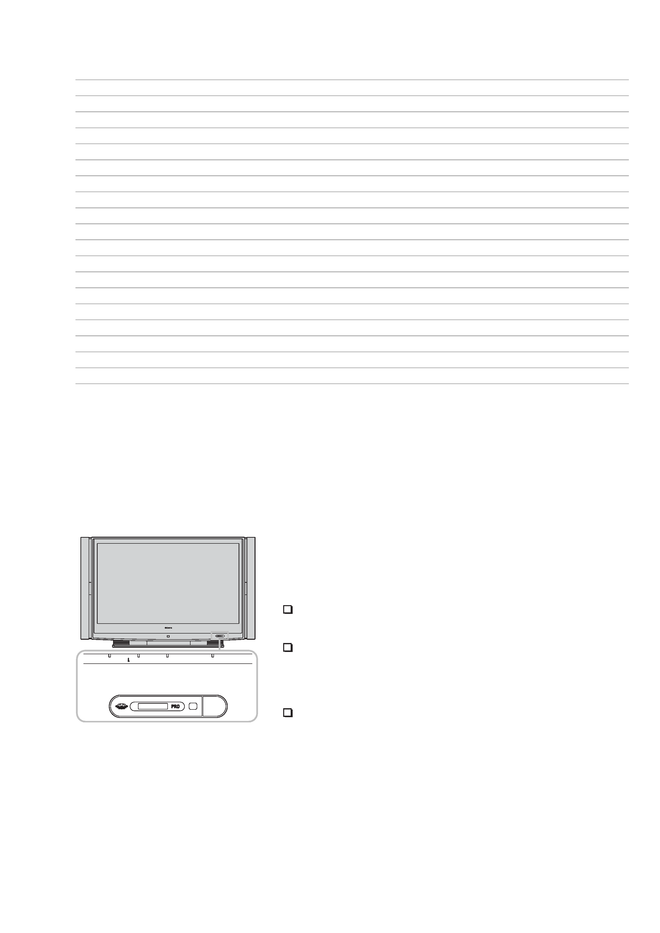
Flashing Indicators on the Front of the TV
The POWER/STANDBY (green or red) and/or LAMP (red) indicators light
or flash if there is a problem with or change in the condition of the SXRD
projection TV.
The POWER/STANDBY (green) indicator flashes.
The lamp for the light source is ready to turn on.
The POWER/STANDBY (red) indicator flashes three times.
The lamp cover is not attached securely. When you secure the lamp
cover, the POWER/STANDBY indicator flashes in red and the SXRD
projection TV enters the standby mode.
The LAMP indicator flashes.
The lamp for the light source has burned out.
Replace it with a new one.
If the SXRD projection TV does not function properly after correcting the
problems, contact qualified Sony personnel.
POWER
STD/DUO
POWER/STANDBY
STANDBY
POWER
LAMP
TIMER
STD / DUO
4
KDS-70Q006
K
RM-Y914
SAFETY CHECK-OUT
( US model only )
After correcting the original service problem, perfom the follow-
ing safety checks before releasing the set to the customer:
l.
Check the area of your repair for unsoldered or poorly-sol-
dered connections. Check the entire board surface for solder
splashes and bridges.
2. Check the interboard wiring to ensure that no wires are
"pinched" or contact high-wattage resistors.
3. Check that all control knobs, shields, covers, ground straps,
and mounting hardware have been replaced. Be absolutely
certain that you have replaced all the insulators.
4. Look for unauthorized replacement parts, particularly tran-
sistors, that were installed during a previous repair. Point them
out to the customer and recommend their replacement.
5. Look for parts which, through functioning, show obvious
signs of deterioration. Point them out to the customer and
recom mend their replacement.
6. Check the line cords for cracks and abrasion. Recommend
the replacement of any such line cord to the customer.
7. Check the condition of the monopole antenna (if any). Make
sure the end is not broken off, and has the plastic cap on it.
Point out the danger of impalement on a broken antenna to
the customer, and recommend the antenna's replacement.
8. Check the B+ and HV to see they are at the values specified.
Make sure your instruments are accurate;be suspicious of
your HV meter if sets always have low HV.
9. Check the antenna temminals, metal trim, "metallized" knobs,
screws, and all other exposed metal parts for AC leakage.
Check leakage as described below.
LEAKAGE TEST
The AC leakage from any exposed metal part to earth ground and
from all exposed metal parts to any exposed metal part having a
return to chassis, must not exceed 0.5mA (500 microampers) . Leak-
age current can be measured by any one of three methods.
1. A commercial leakage tester, such as the Simpson 229 or
RCA WT-540A. Follow the manufacturers' instructions to
usc these instruments.
2. A battery-operated AC milliammeter. The Data Precision 245
digital multimeter is suitable for this job.
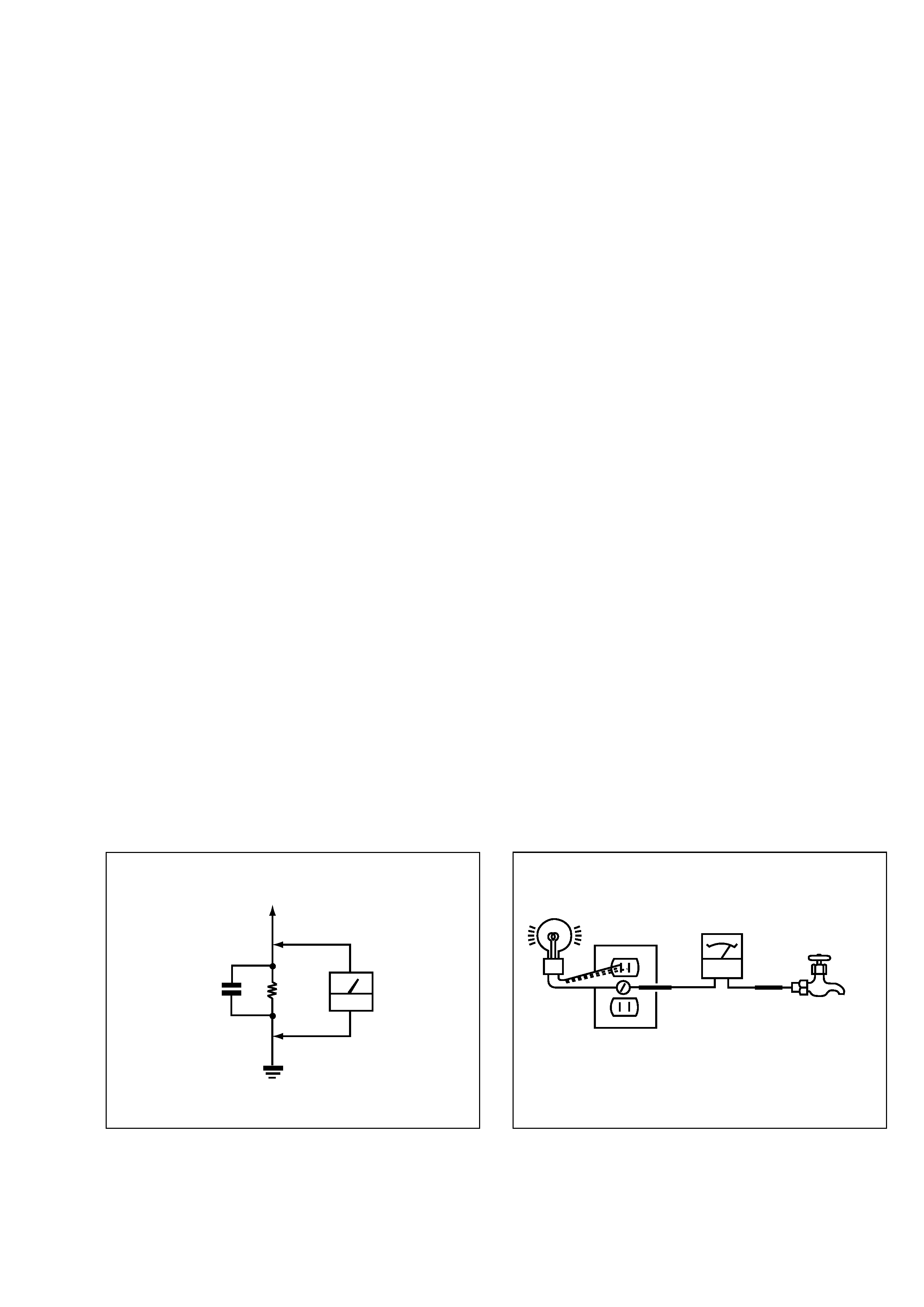
3. Measuring the voltage drop across a resistor by means of a
VOM or battery-operated AC voltmeter. The "limit" indica-
tion is 0.75V, so analog meters must have an accurate low-
voltage scale. The Simpson 250 and Sanwa SH-63Trd are
examples of a passive VOM that is suitable. NearIy all bat-
tery operated digital multimeters that have a 2V AC range
are suitable. (See Fig. A)
HOW TO FIND A GOOD EARTH GROUND
A cold-water pipe is guaranteed earth ground;the cover-plate re-
taining screw on most AC outlet boxes is also at earth ground. If
the retaining screw is to be used as your earth-ground, verify that it
is at ground by measuring the resistance between it and a cold-
water pipe with an ohmmeter. The reading should be zero ohms. If
a cold-water pipe is not accessible, connect a 60-l00 watts trouble
light (not a neon lamp) between the hot side of the receptacle and
the retaining screw. Try both slots, if necessary, to locate the hot
side of the line, the lamp should light at normal brilliance if the
screw is at ground potential. (See Fig. B)
To Exposed Metal
Parts on Set
AC
voltmeter
(0.75V)
1.5k
Earth Ground
Fig. A. Using an AC voltmeter to check AC leakage.
1.5
µ F
Fig. B. Checking for earth ground.
Trouble Light
AC Outlet Box
Ohmmeter
Cold-water Pipe