
COLOR REAR VIDEO PROJECTION
SERVICE MANUAL
AX-1X CHASSIS
MODEL NAME
REMOTE COMMANDER
DESTINATION
CHASSIS NO.
9-965-970-03
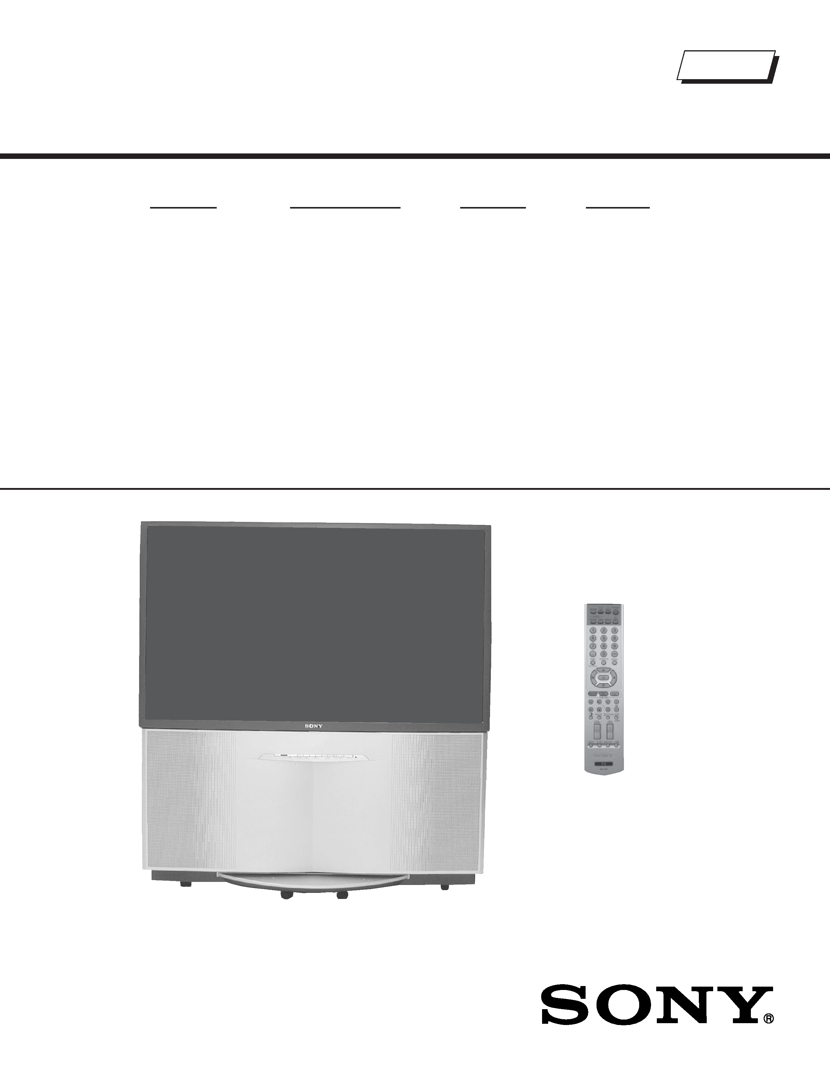
KDP-51WS655
RM-Y915
US/HAWAII
SCC-M39A-A
KDP-57WS655
RM-Y915
US/HAWAII
SCC-M39B-A
HISTORY INFORMATION FOR THE FOLLOWING MANUAL:
ORIGINAL MANUAL ISSUE DATE: 8/2004
:UPDATED ITEM
REVISION DATE
SUBJECT
8/2004
No revisions or updates are applicable at this time.
10/2004
Corrected Note from section 2-12-1. Setup For Adjustment. Note is intended for use by the factory
during production, and should not be performed by service technicians.
(Replaced Page 41 with Page 41)
3/2005
Added Caution statement (Replaced Page 6 with Page 6)
Corrected service mode list (Replaced Page 25 with Page 25)
Added BH Board (PN A-1071-980-A) PWB (Replaced Page 82 with Page 82)
Added alternate BH Board PN to Exploded View section (Replaced Page 91 with Page 91)
New CRTs & Shades introduced for KDP-51WS655 Affects SNs 8,500,001 and up
Updated PN for Blue Shade and Lens for KDP-57WS655
New CRT Coupler Assemblies introduced for KDP-57WS655
Affects SNs 9,702,147-9,702,444 and 9,713,504 and up (Replaced Page 92 with Page 92)
COLOR REAR VIDEO PROJECTION
SERVICE MANUAL
AX-1X CHASSIS
MODEL NAME
REMOTE COMMANDER
DESTINATION
CHASSIS NO.
9-965-970-03
KDP-51WS655
RM-Y915
US/HAWAII
SCC-M39A-A
KDP-57WS655
RM-Y915
US/HAWAII
SCC-M39B-A
Self Diagnosis
Supported model
KDP-51WS655
RM-Y915

KDP-51WS655/57WS655
KDP-51WS655/57WS655
3
TABLE OF CONTENTS
SECTION TITLE
PAGE
SECTION TITLE
PAGE
Specifications ................................................................................. 4
Warnings and Cautions .................................................................. 6
Safety Check-Out ........................................................................... 7
Self-Diagnostic Function................................................................. 8
SECTION 1: DISASSEMBLY................................................................11
1-1. Rear Board Removal.............................................................11
1-2. Chassis Assembly Removal..................................................11
1-3. Service Position ................................................................... 12
1-4. Terminal Board, P Board AND Q Box Assembly Removal ... 12
1-5. BH Board Removal .............................................................. 13
1-6. A Board, D Board, and G Board Removal............................ 13
1-7. High-Voltage Cable Installation and Removal...................... 14
1-8. Picture Tube Removal.......................................................... 14
1-9. Speaker Grille, HA2 Board, and HB3 Board Removal ........ 15
1-10.Beznet Assembly Removal .................................................. 16
1-10-1. Screen Tape Method................................................ 16
1-11. SR Board Removal .............................................................. 17
Wire Dressing....................................................................... 18
SECTION 2: SET-UP ADJUSTMENTS................................................ 22
2-1. Screen Voltage Adjustment (G2) (Coarse Adjustment) ........ 22
2-2. Screen (G2) Adjustment (Fine Adjustment).......................... 22
2-3. Deflection Yoke Tilt Adjustment ............................................ 22
2-4. Focus Lens Adjustment........................................................ 23
2-5. Focus VR Adjustment........................................................... 23
2-6. Centering Magnet Adjustment.............................................. 24
2-7. 2-Pole Magnet Adjustment .................................................. 24
2-8. 4-Pole Magnet Adjustment ................................................... 24
2-9. Defocus Adjustment (Blue)................................................... 24
2-10.Electrical Adjustments by Remote Commander................... 25
2-10-1. Method of Entering the Service Adjustment Mode .. 25
2-10-2. Memory Write Confirmation Method ........................ 25
2-10-3. Adjusting Buttons and Indicator ............................... 25
2-11. Adjustable Service Data Lists .............................................. 26
2-11-1. ID Map Table............................................................ 40
2-12.Registration Adjustment (PJE Mode Only)........................... 41
2-12-1. Setup for Adjustment ............................................... 41
2-12-2. Main Deflection Adjustment ..................................... 41
2-12-3. Operation Method for Projector Engine Mode ......... 42
2-13.PJE Adjustment (Sub Deflection Adjustment) ...................... 43
2-13-1. Adjustment for NTSC Full Mode .............................. 44
2-13-2. Copying All Registration Data to Other Modes ........ 46
2-14.Auto Registration Offsets ..................................................... 46
2-15.Auto Registration Error Codes ............................................. 47
2-16.Auto Registration Diagnostics .............................................. 48
SECTION 3: SAFETY-RELATED ADJUSTMENTS............................. 49
D BOARD ..................................................................................... 49
3-1. HV Regulation Circuit Check and Adjustment...................... 49
3-2. HV Hold Down Circuit Operation Check .............................. 49
G BOARD ..................................................................................... 50
3-3. +B Max Voltage Confirmation .............................................. 50
3-4. +B OVP Confirmation........................................................... 50
SECTION 4: CIRCUIT ADJUSTMENTS.............................................. 51
4-1. P & P Sub Contrast Adjustment (Video) (SCON) ................. 51
4-2. P & P Sub Contrast Adjustment (RF) (SCON) ..................... 51
4-3. P & P Sub-Hue and Sub-Color Adjustment Video
(SHUE, SCOL) ..................................................................... 51
4-4. P & P Sub-Hue and Sub-Color Adjustment (RF)
(SHUE, SCOL) .................................................................... 51
4-5. Blue Offset Adjustment......................................................... 52
SECTION 5: DIAGRAMS..................................................................... 53
5-1. Circuit Boards Location ........................................................ 53
5-2. Printed Wiring Boards and
Schematic Diagrams Information ......................................... 53
5-3. Block Diagrams .................................................................... 55
Power Block Diagram........................................................... 55
Audio Signal Path Block Diagram ........................................ 56
Video Path Block Diagram ................................................... 57
SYNC/OSD Path Block Diagram.......................................... 58
5-4. Schematics and Supporting Information ............................. 59
CR Board Schematic Diagram ............................................ 59
CB Board Schematic Diagram ............................................ 60
CG Board Schematic Diagram ............................................ 61
VM Board Schematic Diagram ............................................ 64
A Board Schematic Diagram (1 of 6).................................... 65
A Board Schematic Diagram (2 of 6).................................... 66
A Board Schematic Diagram (3 of 6).................................... 67
A Board Schematic Diagram (4 of 6).................................... 68
A Board Schematic Diagram (5 of 6).................................... 69
A Board Schematic Diagram (6 of 6).................................... 70
D Board Schematic Diagram (1 of 2) ................................... 75
D Board Schematic Diagram (2 of 2) ................................... 76
BH Board Schematic Diagram (1 of 2)................................. 80
BH Board Schematic Diagram (2 of 2)................................. 81
G Board Schematic Diagram ............................................... 83
HA2 Board Schematic Diagram .......................................... 86
P Board Schematic Diagram................................................ 87
SR Board Schematic Diagram ............................................ 88
HB3 Board Schematic Diagram ........................................... 88
SECTION 6: EXPLODED VIEWS ........................................................ 90
6-1. Cover.................................................................................... 90
6-2. Chassis ................................................................................ 91
6-3. Picture Tube ......................................................................... 92
SECTION 7: ELECTRICAL PARTS LIST........................................... 93
KDP-51WS655/57WS655
KDP-51WS655/57WS655
4
120V AC, 60Hz
260W
Under 1 W
Under 16 W
HDMI IN
Video
1080i, 720p, 480p, 480i
Audio
Two channel linear PCM 32, 44.1, and 48 kHz, 16, 20,
and 24 bit
Video (IN)
4 total (1 on front panel)
1Vp-p, 75ohms unbalanced, sync negative
S Video (IN)
3 total (1 on front panel)
Y: 1Vp-p, 75ohms unbalanced, sync negative
C: 0.286Vp-p (Burst signal), 75ohms
Digital Audio Optical Output
PCM/Dolby Digital
1 Total
Optical Rectangular
SPECIFICATIONS
Design and specifications are subject to change without notice.
Power Requirements
Power Consumption (W)
In Use (Max)
In Standby
In CableCARD Standby
Inputs/Outputs
Audio (IN)
7 total (1 on front panel)
500 mVrms (100% modulation)
Impedance:47 kilohm
Component Video Input
2 ( Y,PB,PR)
Y: 1.0 Vp-p, 75 ohms unbalanced, sync negative;
PB: 0.7 Vp-p, 75 ohms;
PR: 0.7 Vp-p, 75 ohms
Control S (IN/OUT)
1 total
Variable/Fixed Audio (OUT)
More than 408 m Vrms (Variable) at the maximum volume setting
More than 408 m Vrms (Fixed) Impedance (output):2 kilohms
CableCARD Slot
PCMCIA Type I/II
KDP-51WS655
KDP-51WS655
KDP-57WS655
KDP-57WS655
20W x 2
1194 x 1280 x 666 mm
1326 x 1377 x 692 mm
47 x 501/2 x 261/4 in
521/4 x 541/4 x 271/4 in
79.6 kg
92.3 kg
175.5 lbs
203.5 lbs
Speaker Output (W)
Dimensions (W x H x D)
mm
in
Mass
kg
lbs
CableCARD
TM is a trademark of Cable Television
Laboratories, Inc.
TruSurround, SRS and the ( )® symbol are trademarks
of SRS Labs, Inc.
TruSurround technology is incorporated under license
from SRS Labs, Inc.
BBE and BBE Symbol are trademarks of BBE Sound,
Inc. and are licensed by BBE Sound, Inc. under U.S.
Patent No. 4,638,258 and 4,482,866.
Manufactured under license from
Dolby Laboratories Licensing
Corporation. Dolby and the double-D
symbol are trademarks of Dolby
Laboratories Licensing Corporation.
This TV incorporates High-Definition
Multimedia Interface (HDMI
TM)
technology. HDMI, the HDMI logo
and High-Definition Multimedia
Interface are trademarks or registered
trademarks of HDMI Licensing LLC.
WEGA, Steady Sound, Digital Reality Creation,
CineMotion, Memory Stick, Memory Stick Duo,
Memory Stick PRO, Memory Stick PRO Duo,
MagicGate, MID and Twin View are trademarks of Sony
Corporation.

KDP-51WS655/57WS655
KDP-51WS655/57WS655
5
Projection System
3 picture tubes, 3 lenses, horizontal in-line system
Picture Tube
7-inch high-brightness monochrome tubes (6.3 raster size),
with optical coupling and liquid cooling system.
Projection Lenses
High performance, large diameter hybrid lens F1.1
Antenna
75 ohm external terminal for VHF/UHF
Television System
NTSC, American TV Standard
ATSC (8VSB terrestrial) ATSC compliant 8VSB
QAM on cable ANSI/SCTE 07 2000
Channel Coverage
Terrestrial (analog)
2-69
Cable TV (analog)
1-125
Terrestrial (digital)
2-69
Cable TV (digital)
1-135
Screen Size (measured diagonally)
51 inches (KDP-51WS655)
57 inches (KDP-57WS655)
Supplied Accessories
Remote Control RM-Y915
Batteries (2) size AA (R6)
Optional Accessories
A/V Cable (VMC-810/820/830 HG)
Audio Cable (RKC-515HG)
Component Video Cable (VMC-10/30 HG)