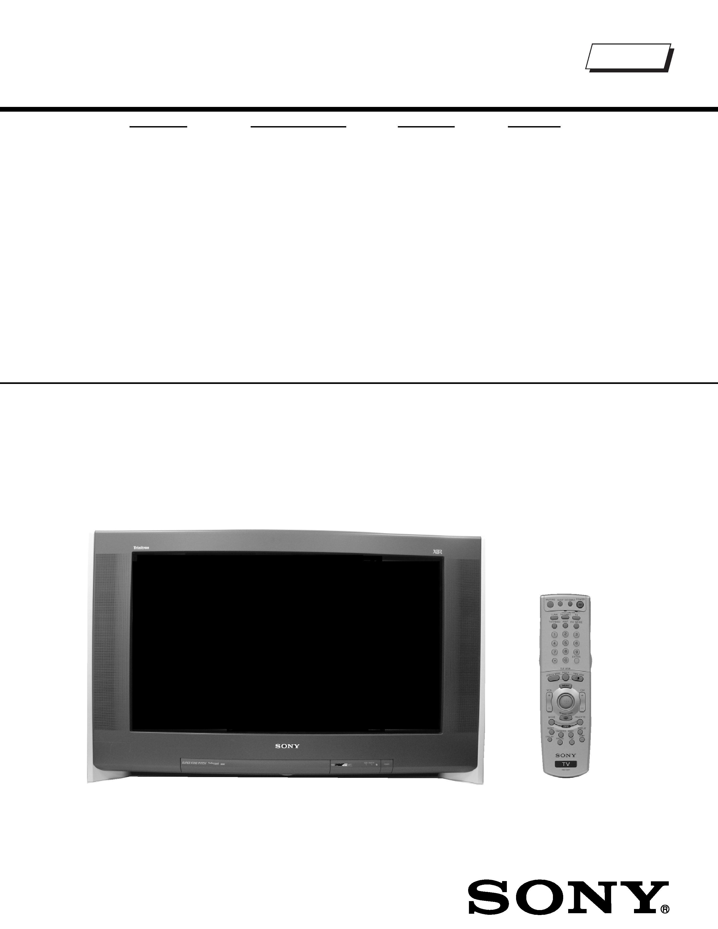
TRINITRON
® COLOR TELEVISION
SERVICE MANUAL
DA-4 CHASSIS
MODEL NAME
REMOTE COMMANDER
DESTINATION
CHASSIS NO
9-965-965-07
KD-30XS955
RM-Y199
US
SCC-S66U-A
KD-30XS955
RM-Y199
HAWAII
SCC-S69K-A
KD-34XBR960
RM-Y201
US
SCC-S66V-A
KD-34XBR960
RM-Y201
HAWAII
SCC-S69L-A
KD-34XS955
RM-Y199
US
SCC-S66W-A
KD-34XS955
RM-Y199
CANADA
SCC-S70V-A
KD-34XS955
RM-Y199
HAWAII
SCC-S69M-A
KD-36XS955
RM-Y199
US
SCC-S66X-A
KD-36XS955
RM-Y199
HAWAII
SCC-S69N-A
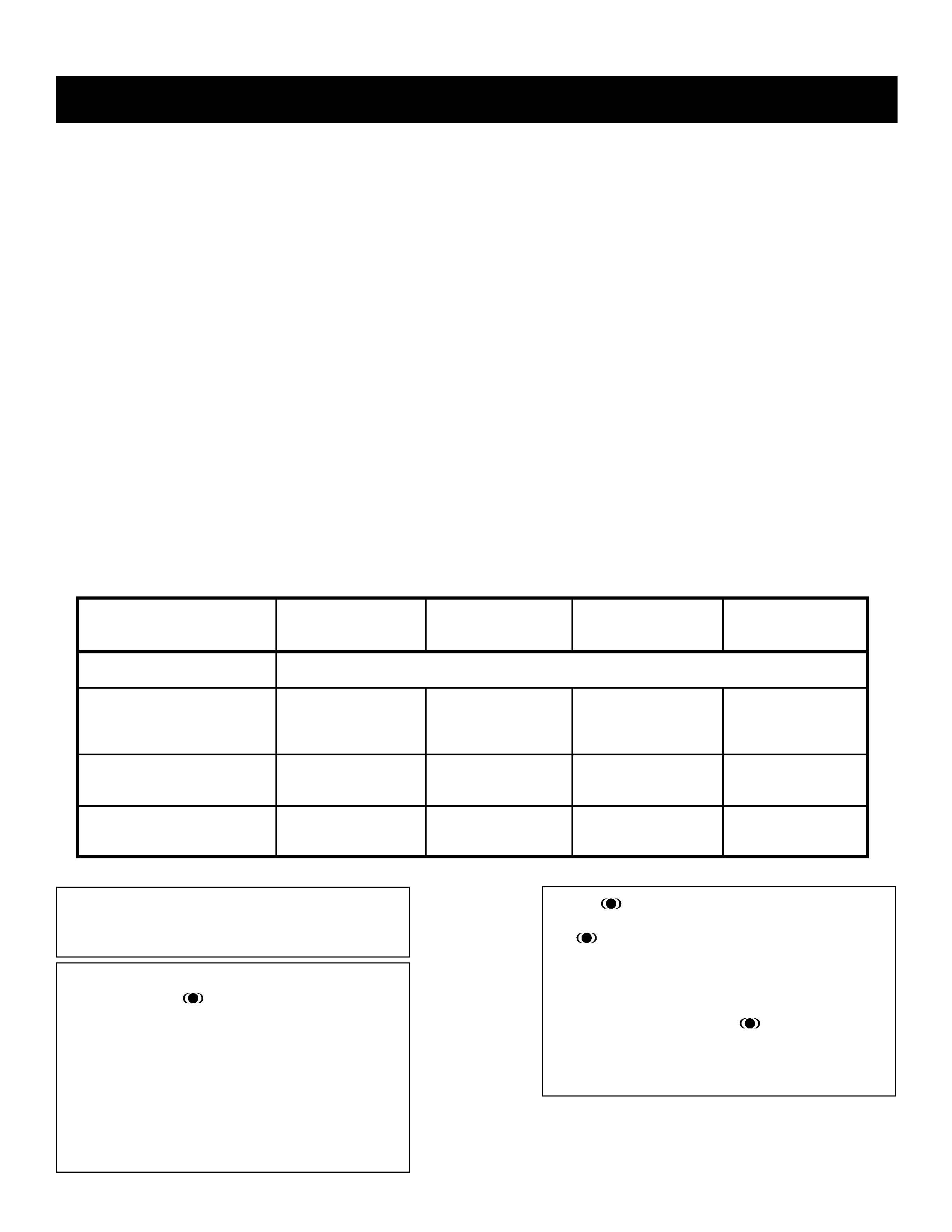
HISTORY INFORMATION FOR THE FOLLOWING MANUAL:
This manual is for units within the following S/N range:
For KD-30XS955 - S/N 4,000,001 - 4,500,000 and 8,000,001 - 8,500,000
For KD-34XS955 - S/N 9,000,001 - 9,500,000 and 8,000,001 - 8,500,000
ORIGINAL MANUAL ISSUE DATE: 6/2004
UPDATED ITEM
REVISION DATE
SUBJECT
6/2004
No revisions or updates are applicable at this time.
7/2004
Reissue entire manual
11/2004
Updated Table of Contents (Replace Pg. 3 with Pg. 3)
Added Note to Cable Wire Dressing section (Replace Pg. 13 with Page 13)
Updated 2-1. Beam Landing instructions (Replace Pg. 34 with Pg. 34)
Updated ID Map Table (Replace Pg. 92 with Pg. 92)
Updated Circuit Boards Location diagram (Replace Pg. 93 with Pg. 93)
Replaced P Board Schematic Diagram (Replace Pg. 99 with Pg. 99)
Added PA Board Schematic and PWBs (Add Pgs. 100-A and 100-B)
Updated BY Board PWBs (Replace Pgs. 111 & 112 with Pgs. 111 &112)
Updated DZ Board Schematic (2 of 2) (Replace Pg. 123 with Pg. 123)
Added PA Board to Exploded View section (Replace Pgs. 141, 143, & 145 with Pgs. 141, 143, & 145)
Added PA Board information to Electrical Parts Lists (Add Pgs. 204-208)
12/2004
Corrected Self-Diagnostic Circuit Diagram (Replace Pg. 9 with Pg. 9)
2/2005
Updated 2-1. Beam Landing instructions (Replace Pg. 34 with Pg. 34)
Reorganized 2-2. Convergence and 2-3. V-Pin and V-Cen Adjusment instructions
(Replace Pg. 35 with Pg. 35)
Corrected Block Diagram (Replace Pg. 94 with Pg. 94)
Updated DZ Schematic Diagram to correct IC5005 pin 3 (Replace Pg. 122 with Pg. 122)
Corrected Exploded View diagrams to show correct placement of Neck Assembly & Landing Coil Correction
Corrected PN for Control Door & Power Button, Added Door Damper
(Replace Pgs. 142, 144, &146 with Pgs. 142, 144, &146)
6/2005
Added Serial Number range to Front Cover and History Information pages.
7/2005
Revised Serial Number range to Front Cover and History Information pages.
Corrected Model Names on Exploded View. Changed `KV' to `KD'. (Replace Pgs 143 and 144)
TRINITRON
® COLOR TELEVISION
SERVICE MANUAL
DA-4 CHASSIS
MODEL NAME
REMOTE COMMANDER
DESTINATION
CHASSIS NO
9-965-965-07
KD-30XS955
RM-Y199
US
SCC-S66U-A
KD-30XS955
RM-Y199
HAWAII
SCC-S69K-A
KD-34XBR960
RM-Y201
US
SCC-S66V-A
KD-34XBR960
RM-Y201
HAWAII
SCC-S69L-A
KD-34XS955
RM-Y199
US
SCC-S66W-A
KD-34XS955
RM-Y199
CANADA
SCC-S70V-A
KD-34XS955
RM-Y199
HAWAII
SCC-S69M-A
KD-36XS955
RM-Y199
US
SCC-S66X-A
KD-36XS955
RM-Y199
HAWAII
SCC-S69N-A
Self Diagnosis
Supported model
KD-34XBR960
RM-201
This manual is for units within the following S/N range:
For KD-30XS955 - S/N 4,000,001 - 4,500,000 and 8,000,001 - 8,500,000
For KD-34XS955 - S/N 9,000,001 - 9,500,000 and 8,000,001 - 8,500,000

3
KD-30XS955/34XBR960/34XS955/36XS955
KD-30XS955/34XBR960/34XS955/36XS955
TABLE OF CONTENTS
SECTION TITLE
PAGE
SECTION TITLE
PAGE
Specifications ................................................................................. 4
Warnings and Cautions .................................................................. 6
Safety Check-Out ........................................................................... 7
Self-Diagnostic Function................................................................. 8
SECTION 1: DISASSEMBLY................................................................11
1-1. Rear Cover Removal.............................................................11
1-2. Chassis Assembly Removal..................................................11
1-3. Service Position ....................................................................11
1-4. Picture Tube Removal.......................................................... 12
Anode Cap Removal Procedure .......................................... 12
Cable Wire Dressing ............................................................ 13
SECTION 2: SET-UP ADJUSTMENTS................................................ 34
2-1. Beam Landing...................................................................... 34
2-2. Convergence........................................................................ 35
2-2.1. Vertical and Horizontal Static Convergence ............ 35
2-3. V-PIN and V-CEN Adjustment.............................................. 35
2-3.1. Operation of BMC (Hexapole) Magnet .................... 35
2-3.2. TLH Plate Adjustment.............................................. 36
2-3.3. Screen-Corner Convergence................................... 36
2-3.4. Dynamic Convergence Adjustments........................ 36
2-4. Focus Adjustment................................................................. 37
2-4.1. Dynamic Focus/Dynamic Quadra-Pole Data........... 37
2-5. Screen (G2).......................................................................... 38
2-6. Picture Quality Adjustments ................................................. 38
2-6.1. Video Input - Sub Contrast Adjustment.................... 38
2-6.2. Video Input - Sub Hue/Sub Color Adjustment.......... 39
2-6.3. RF Input - Sub Contrast Adjustment........................ 39
2-6.4. RF Input - Sub Hue/Sub Color Adjustment.............. 40
2-7. White Balance (CRT) and Sub Bright Adjustment................ 40
2-7.1. Color Offset Adjustment Procedure ......................... 41
2-8. H Raster Center Adjustment ................................................ 41
2-9. Picture Distortion Adjustments ............................................. 42
2-9.1. NTSC (DRC) Full Mode Adjustment ........................ 42
2-9.2. 1080i HD Mode Adjustment..................................... 43
2-9.3. Vertical Compressed Mode Check and Confirmation
(For 4x3 CRT Only) ................................................. 43
2-9.4. Normal, Zoom and Wide Zoom modes.................... 43
SECTION 3: SAFETY RELATED ADJUSTMENTS............................. 44
3-1. Preparation Before Confirmation.......................................... 44
3-1.1 Hold-Down Operation Confirmation......................... 44
3-2. B+ Max Confirmation ........................................................... 44
3-3. B+ Voltage Check ................................................................ 44
3-4. High Voltage (HV) Check ..................................................... 44
3-5. Preparation for HV and IK Protector Check ......................... 44
3-6. HV Protector Check ............................................................. 44
3-6-1. Cut Off Condition ..................................................... 44
3-6-2. High Light Condition ................................................ 45
3-7. IK Protector Check............................................................... 45
3-8. Hold Down Check ................................................................ 45
3-9. Restoration........................................................................... 45
3-10.HS Service Flowchart........................................................... 46
HS Service Flowchart Table................................................. 47
SECTION 4: CIRCUIT ADJUSTMENTS.............................................. 48
4-1. Setting Service Adjustment Mode ........................................ 48
4-1.1. Service Adjustment Mode In.................................... 48
4-1.2. Service Adjustment Mode Memory.......................... 48
4-1.3. Reading the Memory ............................................... 48
4-1.4. Adjusting the Picture................................................ 48
4-1.5. Resetting the Data................................................... 48
4-1.6. Resetting the MID NVM Data .................................. 48
4-1.7. Resetting the System NVM Data............................. 48
4-1.8. Copy Function.......................................................... 48
4-2. Memory Write Confirmation Method .................................... 49
4-3. Remote Adjustment Buttons and Indicators......................... 49
4-4. Service Data......................................................................... 50
KD-34XBR960 Service Data Only........................................ 50
KD-30XS955/34XS955/36XS955 Service Data Only........... 71
4-5. ID Map Table........................................................................ 92
SECTION 5: DIAGRAMS..................................................................... 93
5-1. Circuit Boards Location........................................................ 93
5-2. Printed Wiring Boards and
Schematic Diagrams Information......................................... 93
5-3. Block Diagrams.................................................................... 94
5-4. Schematics and Supporting information .............................. 97
DL Board Schematic Diagram.............................................. 97
P Board Schematic Diagram................................................ 99
PA Board Schematic Diagram......................................... 100-A
AZ Board Schematic Diagram (1 of 3) ............................... 101
AZ Board Schematic Diagram (2 of 3) ............................... 102
AZ Board Schematic Diagram (3 of 3) ............................... 103
BY Board Schematic Diagram (1 of 5)............................... 106
BY Board Schematic Diagram (2 of 5)............................... 107
BY Board Schematic Diagram (3 of 5)............................... 108
BY Board Schematic Diagram (4 of 5)............................... 109
BY Board Schematic Diagram (5 of 5)................................110
MZ Board Schematic Diagram (1 of 4)................................113
MZ Board Schematic Diagram (2 of 4)................................114
MZ Board Schematic Diagram (3 of 4)................................115
MZ Board Schematic Diagram (4 of 4)................................116
UZ Board Schematic Diagram ............................................119
DZ Board Schematic Diagram (1 of 2)............................... 122
DZ Board Schematic Diagram (2 of 2)............................... 123
HCX Board Schematic Diagram......................................... 127
CX Board Schematic Diagram ........................................... 129
HAX Board Schematic Diagram......................................... 132
HBZ Board Schematic Diagram......................................... 134
WY Board Schematic Diagram .......................................... 136
5-5. Semiconductors (1 of 2)..................................................... 139
Semiconductors (2 of 2)..................................................... 140
SECTION 6: EXPLODED VIEWS...................................................... 141
6-1. Chassis (KD-34XBR960 Only)........................................... 141
6-2. Picture Tube (KD-34XBR960 Only).................................... 142
6-3. Chassis (KD-30XS955/34XS955 Only).............................. 143
6-4. Picture Tube (KD-30XS955/34XS955 Only) ...................... 144
6-5. Chassis (KD-36XS955 Only).............................................. 145
6-6. Picture Tube (KD-36XS955 Only) ...................................... 146
SECTION 7: ELECTRICAL PARTS LIST......................................... 147
4
KD-30XS955/34XBR960/34XS955/36XS955
KD-30XS955/34XBR960/34XS955/36XS955
SPECIFICATIONS
Design and specifications are subject to change without notice.
120V AC, 60Hz
HDMI IN
Video
1080i, 720p, 480p, 480i
Audio Two channel linear PCM 32, 44.1 and 48 kHz,
16, 20, and 24 bit
Video (IN)
4 total (1 on front panel)
1Vp-p, 75ohms unbalanced, sync negative
S Video (IN)
3 total (1 on front panel)
Y: 1Vp-p, 75ohms unbalanced, sync negative
C: 0.286Vp-p (Burst signal), 75ohms
Audio (IN)
7 total (1 on front panel)
500 mVrms (100% modulation)
Impedance:47 kilo ohms
Control S (IN/OUT)
1 total
Power Requirements
Inputs/Outputs
Component Video Input
2 (Y, PB, PR)
Y: 1.0 Vp-p, 75 ohms unbalanced, sync negative
P
B: 0.7 Vp-p, 75 ohms;
P
R: 0.7 Vp-p, 75 ohms
Audio OUT (VAR/FIX)
1 total
At the maximum volume setting
More than 408 mVrms (Variable)
More than 408 mVrms (Fixed)
Impedance (Output):2 kilo ohm
i.LINK (KD-34XBR960 Only)
3 total (1 on front panel)
4-pin S400 i.LINK terminal
Digital Audio Optical Output
PCM/Dolby Digital
1 total
Optical Rectangular
CableCARD Slot
PCMCIA Type I/II
KD-30XS955
KD-34XBR960
KD-34XS955
KD-36XS955
Speaker Output (W)
Power Consumption (W)
In Use (Max)
220 W
270 W
250 W
270 W
In Standby
3 W
3 W
3 W
3 W
In CableCARD Standby
20 W
23 W
20 W
20 W
Dimensions (W x H x D)
mm
898 x 604 x 564.5 mm
994 x 652 x 605 mm
994 x 654 x 604 mm
994 x 776.5 x 634 mm
in 35
3/8 x 23 3/4 x 22 1/4 in
39
1/8 x 25 5/8 x 23 7/8 in
39
1/8 x 25 3/4 x 23 3/4 in
39
1/8 x 30 5/8 x 25 in
Mass
kg
67 kg
89 kg
93 kg
108.2 kg
lbs
148 lbs
196 lbs
205 lbs
238.5 lbs
7.5 W x 2
15W Subwoofer
SRS (SOUND RETRIEVAL SYSTEM)
The
SRS (SOUND RETRIEVAL SYSTEM) is manufactured
by Sony Corporation under license from SRS Labs, Inc. It is
covered by U.S. Patent No. 4,748,669. Other U.S. and foreign
patents pending.
The word `SRS' and the SRS symbol
are registered trade-
marks of SRS Labs, Inc. BBE and BBE symbol are trademarks of
BBE Sound, Inc. and are licensed by BBE Sound, Inc. under U.S.
Patent No. 4,638,258 and 4,482,866.
TruSurroundTM
by
SRS
®
TruSurround is a trademark of SRS Labs, Inc. SRS and the SRS
symbol are registered trademarks of SRS Labs, Inc. in the United
States and in select foreign countries. SRS and TruSurround are
incorporated under license from SRS Labs, Inc. and are protected
under United States Patent Nos. 4,748,669 and 4,841,572 with
numerous additional issued and pending foreign patents. Pur-
chase of this product does not convey the right to sell recordings
made with the TruSurround technology.
© 2004 Dolby Laboratories, Inc.
Dolby, Pro Logic, and the double-D symbol are registered
trademarks of Dolby Laboratories.

5
KD-30XS955/34XBR960/34XS955/36XS955
KD-30XS955/34XBR960/34XS955/36XS955
Television system
American TV standard, NTSC
ATSC compliant (8 VSB terrestrial)
ATSC compliant 8 VSB terrestrial
QAM on cable
ANSI/SCTE 07 2000
Channel coverage
Analog
VHF: 2-13/ UHF: 14-69/ CATV: 1-125
Digital
VHF: 2-13/ UHF: 14-69/ CATV: 1-135
Picture tube
FD Trinitron
®
tube
Visible screen size
30-inch picture measured diagonally (KD-30XS955 Only)
34-inch picture measured diagonally (KD-34XBR960/34XS955 Only)
36-inch picture measured diagonally (KD-36XS955 Only)
Actual screen size
32-inch measured diagonally (KD-30XS955 Only)
36-inch measured diagonally (KD-34XBR960/34XS955 Only)
38-inch measured diagonally (KD-36XS955 Only)
Antenna
75 ohm external terminal for VHF/UHF
Supplied Accessories
Remote Commander
RM-Y199 (KD-30XS955/34XS955/36XS955 Only)
RM-Y201 (KD-34XBR960 Only)
Two Size AA (R6) Batteries
Optional Accessories
AV Cable: VMC-810/820/830 HG
Audio Cable: RKC-515HG
Component Video Cable: VMC-10/30 HG
ILINK cables: (KD-34XBR960 Only)
VMC-IL4415 (4-pin to 4-pin, 1.5 meters)
VMC-IL4435 (4-pin to 4-pin, 3.5 meters)
TV Stand:
SU-30HX1 (KD-30XS955 Only)
SU-34XBR3 (KD-34XBR960 Only)
SU-34HX1 (KD-34XS955 Only)
SU-36HX1 (KD-36XS955 Only)