-- 1 --
INT-W200 / INT-WJ200
MICROFILM
INTERNET TERMINAL
INT-W200
INT-WJ200
RM-Y801
RM-J313
SERVICE MANUAL
U.S. Model
Japan Model
SPECIFICATIONS
Terminals:
Video In/Out (1)
Power Requirements:
120V AC 60Hz (U.S.)
S-Video Out (1 )
100V AC 50/60Hz (JAPAN)
Audio (R/L) In/Out (1)
Tel Line (1)
Power Consumption:
38 W max
Printer Port (DB25) (1)
8 W stand by
WEBTV port (96 pin) (1)
IR Blaster Out (1) (U.S.)
Supplied Accessories:
Remote Control:
CH3-CH4 Switch (1) (U.S.)
RM-Y801(1)
(U.S.)
VHF/UHF In/Out (1) (U.S.)
RM-J313 (1) (JAPAN)
AC In (1)
Size AA Batteries (2)
Mic Input (JAPAN)
AC Power Cord (1) 1.9m
A/V (Audio/Video) Cable (1) 1.5m
Telephone Cable (1) 7.5m
Dimensions:
355 mm x 73.5 mm x 226mm (w/h/d)
T- Splitter (1)
(w/h/d)
14 x 2 7/8" x 8 57/64"
IR Blaster (1) (U.S.)
S-Video Cable 1.5m (1)
Weight:
3 kg (6 lbs. 10 oz.) (U.S.)
Coaxial Cable (1) 1.5m (U.S.)
2.9kg (6 lbs. 6 oz.) (JAPAN)
Optional Accessories:
Wireless Keyboard
RM-KW100, KI-W200 (U.S.)
KI-WJ200 (JAPAN)
-- 2 --
INT-W200 / INT-WJ200
SAFETY CHECK-OUT
(U.S. Model only)
After correcting the original service problem, perform the following safety checks before releasing the unit to the customer:
1. Check the area of your repair for unsoldered or
poorly-soldered connections. Check the entire board
surface for solder splashes and bridges.
2. Check the interboard wiring to ensure that no wires
are "pinched" or contact high-wattage resistors.
3. Check that all control knobs, shields, covers,
ground straps, and mounting hardware have been
replaced. Be absolutely certain that you have
replaced all the insulators.
4. Look for unauthorized replacement parts,
particularly transistors, that were installed during
a previous repair. Point them out to the customer
and recommend their replacement.
5. Look for parts which, though functioning, show obvious
signs of deterioration. Point them out to the customer
and recommend their replacement.
6. Check the line cords for cracks and abrasion. Recommend
the replacement of any such line cord to the customer.
7. Check the B+ and HV to see if they are specified values.
Make sure your instruments are accurate; be suspicious
of your HV meter if sets always have low HV.
8. Check the antenna terminals, metal trim, "metallized"
knobs, screws, and all other exposed metal parts for AC
Leakage. Check leakage as described below.
LEAKAGE TEST
The AC leakage from any exposed metal part to earth ground
and from all exposed metal parts to any exposed metal part having
a return to chassis, mU.S.t not exceed 0.5 mA (500 microampere).
Leakage current can be measured by any one of three methods:
1. A commercial leakage tester, such as the Simpson 229 or
RCA WT-540A. Follow the manufacturers' instructions to
use these instructions.
2. A battery-operated AC milliameter. The Data Precision
245 digital multimeter is suitable for this job.
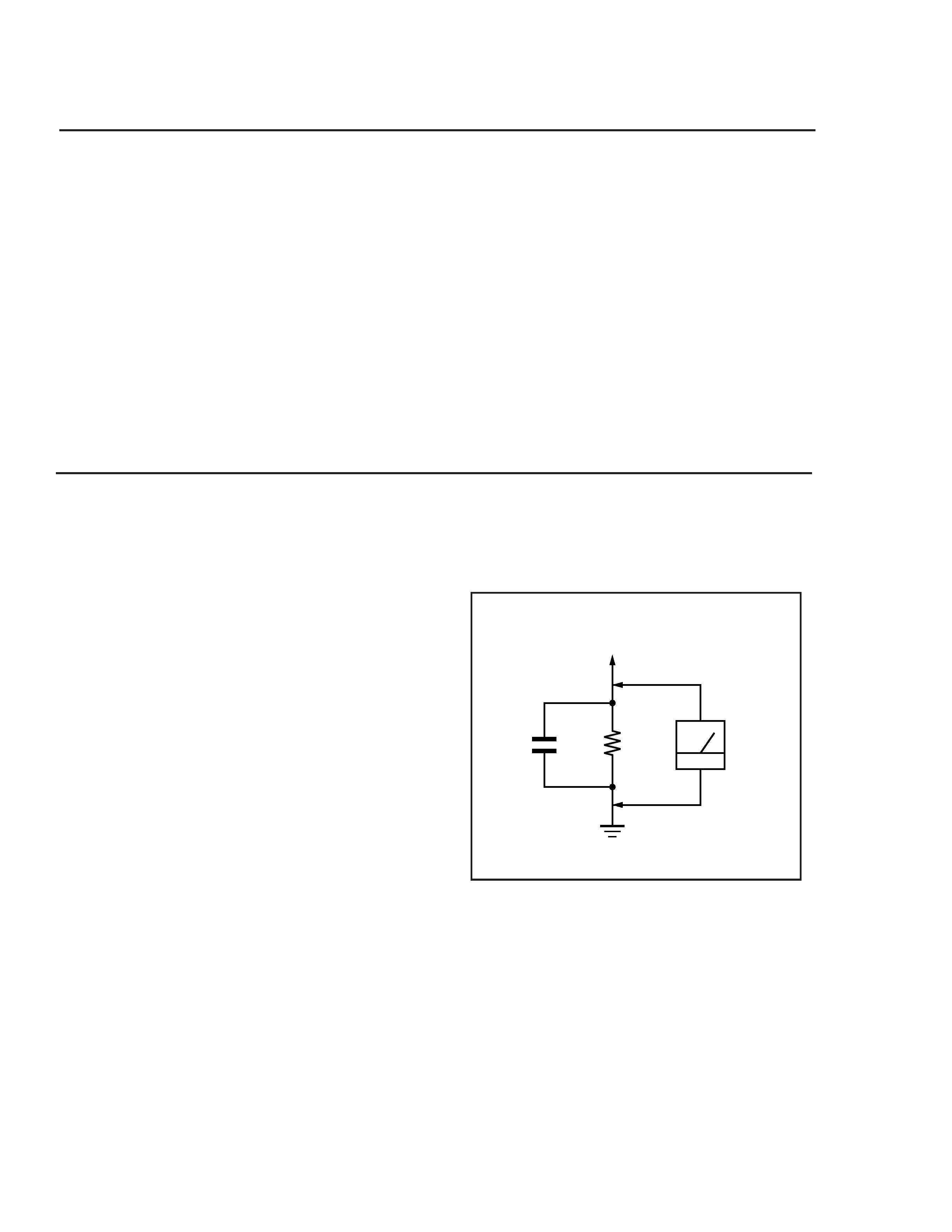
3. Measuring the voltage drop across a resistor by means of
a VOM or battery-operated AC voltmeter. The "limit"
indication is 0.75 V, so analog meters mU.S.t have an accu-
rate low voltage scale. The Simpson's 250 and Sanwa SH-
63Trd are examples of passive VOMs that are suitable.
Nearly all battery operated digital multimeters that have
a 2V AC range are suitable. (See Fig. A)
Fig. A. usng an AC voltmeter to check AC leakage.
1.5 k W
0.15 µF
AC
Voltmeter
(0.75 V)
To Exposed Metal
Parts on Set
Earth Ground

-- 3 --
INT-W200 / INT-WJ200
TABLE OF CONTENTS
Section
Title
Page
1. GENERAL ................................................................................... 4
2. DISASSEMBLY
2-1. Upper Case and Front Cover Removal....................... 8
2-2. Power Supply Board, Hard Disk and
Main PC Board Removal ...............................................8
3. SYSTEM DIAGNOSTIC TEST............................................. 9
4. DIAGRAMS
4-1. Block Diagrams ...............................................................10
4-2. Power Supply Schematic ............................................. 11
4-3. Power Supply Part List ................................................. 12
4-4. Main PC Board Schematic ............................................ 13
5. EXPLODED VIEW.................................................................... 47
6. ELECTRICAL PARTS LIST ................................................ 48
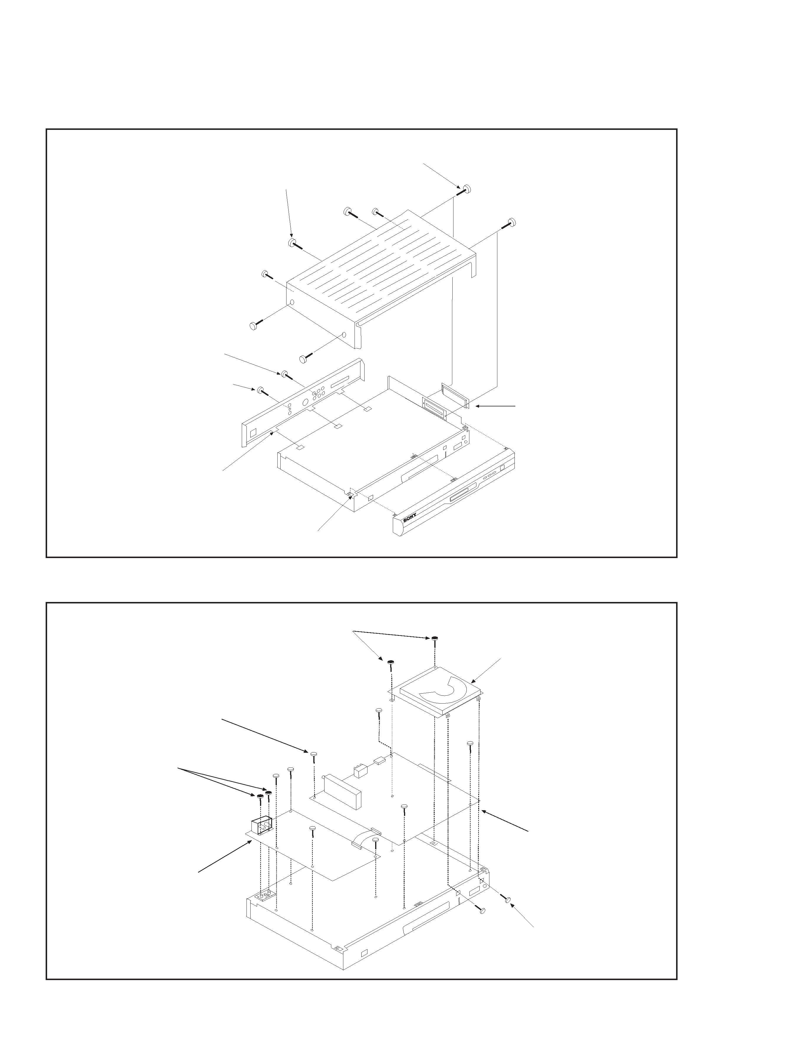
-- 8 --
INT-W200 / INT-WJ200
PC BOARD ASSY
POWER SUPPLY BOARD
EIGHT (8) SCREWS +BVTT (S) 3x6
TWO (2) SCREWS +BVTP 3x12
TWO (2) SCREWS +BVTT (S) 3x6
HARD DISK DRIVE
TWO (2) SCREWS +BVTT (S) 3x6
2-2. POWER SUPPLY BOARD, HARD DISK AND MAIN PC BOARD REMOVAL
2-1. UPPER CASE AND FRONT COVER REMOVAL
SECTION 2
DISASSEMBLY
COVER
CONNECTOR
FOUR (4) SIDE OF COVER SCREWS
(S) TIGHT +PTTWH 3X6
ONE (1) REAR PANEL SCREW
(S) TIGHT +PTTWH 3X6
FOUR (4) FRONT
PANEL LATCHES
THREE (3) BACK
PANEL LATCHES
FOUR (4) BACK OF COVER
SCREWS +BVTT 3X6
ONE (1) REAR PANEL
SCREW 3X12
-- 9 --
INT-W200 / INT-WJ200
SECTION 3
SYSTEM DIAGNOSTIC TEST
3-1.
INTRODUCTION:
The following procedure is to test the WebTV (INT-W200/WJ200).
3-2.
TEST EQUIPMENT REQUIRED:
1. PC (use Windows '95)
2. Oscilloscope (HP) or equivalent.
3. Digital Meter (FLUKE 87) or equivalent.
4. Donglizer (provided with WebTV)
5. +5Vdc Adapter
6. Two D-Sub 9 pins (female connector)
3-3. COMPUTER SET-UP:
1. Open "Start Windows," go to "Program," click on "Accessories," and select "Hyperterminal."
2. Click the "Hyperterminal" icon, and under "Connection Description", enter name and click "OK."
3. In the "Phone Number" window, connect using: select Direct to COM1.
4. Under "Port Settings," set as follows:
Bits per second:
19200
Data bits:
8
Parity:
None
Stop bits:
1
Flow Control:
None
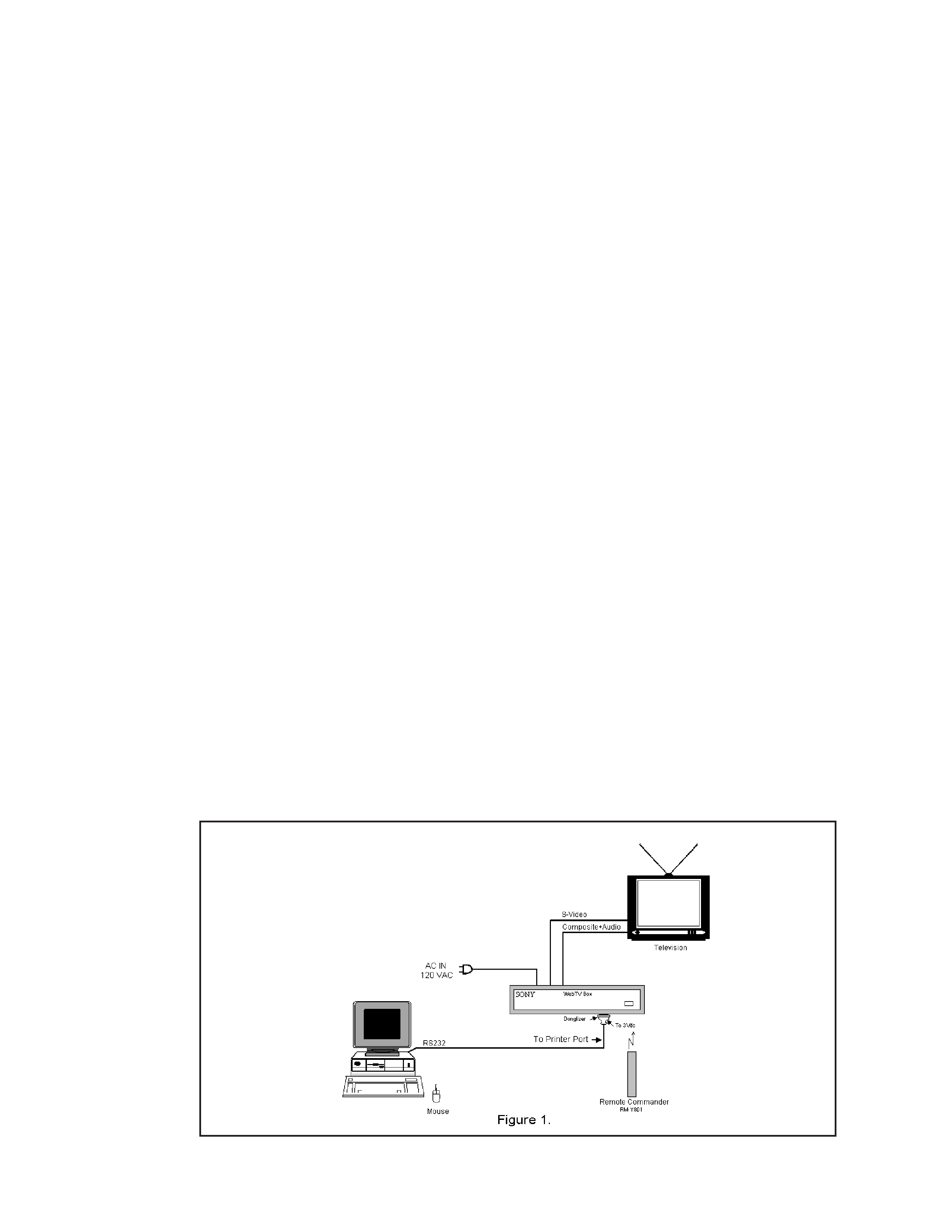
3-4. TEST PROCEDURE:
1. Connect the WebTV unit to PC terminal as shown in Figure 1 below.
2. Energize the WebTV unit.
3. The computer monitor will show the list of diagnostics choices.
4. In order to select a test, type the number associated with the test on the keyboard, and press "enter."
The output data will appear on the screen.
5. To save the data, go to the "Transfer" menu, select "Capture Text," and click "Start."
6. The data you captured will be in the Hyperterminal folder.
7. In order to read the data, confirm that the "Append line feeds to incoming lines ends" option is selected in the
ASCII set-up menu.
Note: Two D-sub 9 pin configuration connections: Pin5 to Pin5, Pin2 to Pin3, Pin3 to Pin2