Ver 1.1 2001.03
SERVICE MANUAL
FM STEREO/SW/MW/LW
PLL SYNTHESIZED RECEIVER
SPECIFICATIONS
US Model
Canadian Model
AEP Model
E Model
Tourist Model
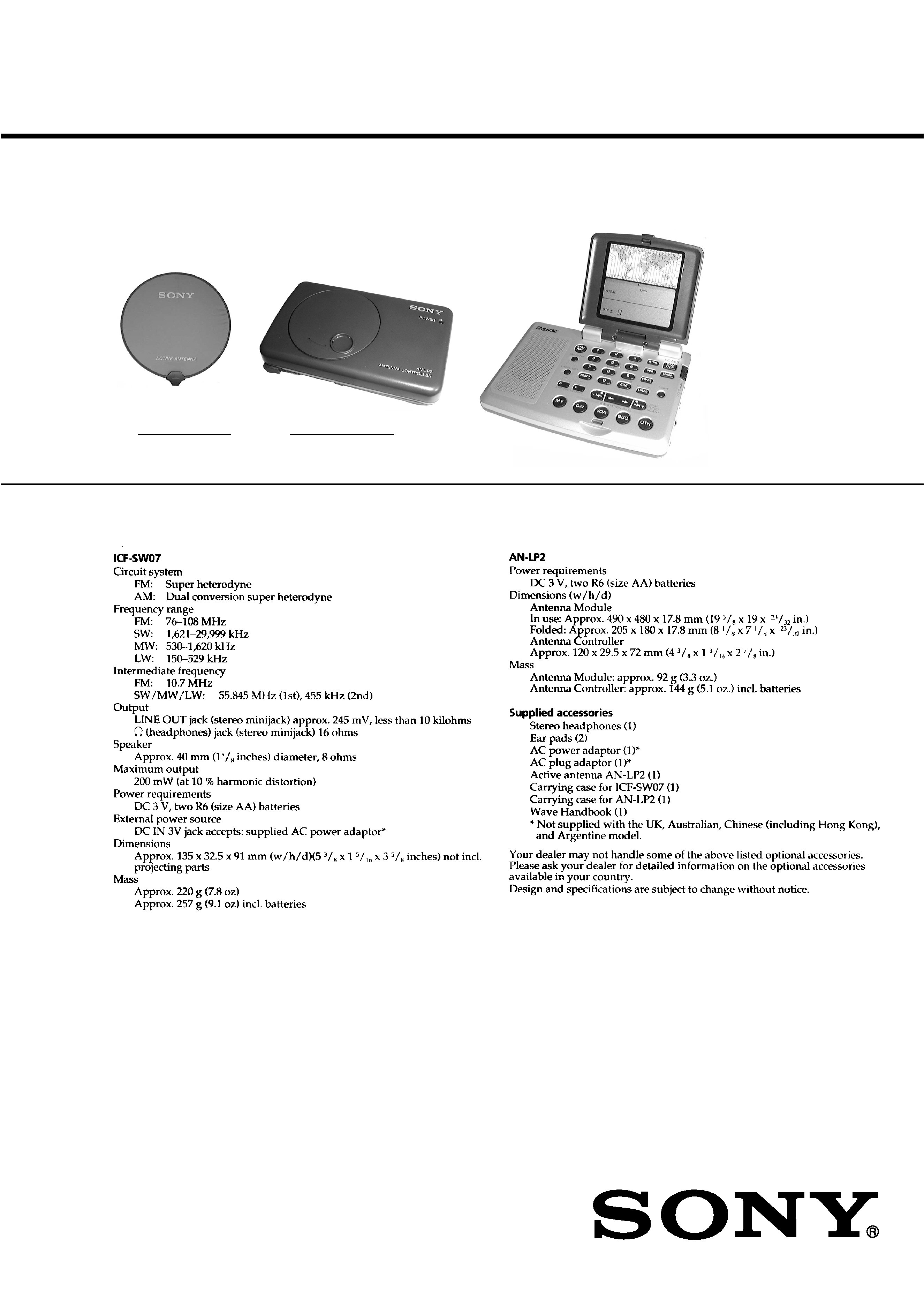
ICF-SW07
AN-LP2
ICF-SW07
Antenna mdule
Antenna Controller
AN-LP2
9-926-933-12
2001C0200-1
© 2001.3
Sony Corporation
Audio Entertainment Group
General Engineering Dept.

2
Specifications ............................................................................ 1
1. SERVICE NOTE ........................................................... 3
2. GENERAL ...................................................................... 4
3. DISASSEMBLY
3-1. Cabinet (Lower), Cabinet ASSY .............................. 25
3-2. Chassis ASSY ........................................................... 26
3-3. Main Board ............................................................... 26
3-4. Key Board ................................................................. 27
3-5. Microcomputer Board ............................................... 27
3-6. Cabinet (Front), Reel ASSY ..................................... 28
3-7. Cabinet (Rear), Reel Board, Control Board ............. 28
4. ELECTRICAL ADJUSTMENTS ........................ 29
5. DIAGRAMS
5-1. Explanation of IC Terminals ................................... 34
5-2. Block Diagrams ....................................................... 37
5-3. Printed Wiring Boards (Main Section) .................... 41
5-4. Schematic Diagram (Main Section) ........................ 46
5-5. Printed Wiring Boards (Key Section) ..................... 50
5-6. Schematic Diagram (Key Section) .......................... 53
5-7. Printed Wiring Boards (Microcomputer Section) ... 55
5-8. Schematic Diagram (Microcomputer Section) ....... 56
5-9. Printed Wiring Boards (Antenna Section) .............. 59
5-10. Schematic Diagram (Antenna Section) ................... 61
6. EXPLODED VIEWS
6-1. Cabinet Section ......................................................... 64
6-2. Chassis Section ......................................................... 65
6-3. Antenna Controller Section ...................................... 66
6-4. SW Loop Antenna Section ....................................... 67
7. ELECTRICAL PARTS LIST ................................... 68
ATTENTION AU COMPOSANT AYANT RAPPORT
À LA SÉCURITÉ!
LES COMPOSANTS IDENTIFIÉS PAR UNE MARQUE
! SUR LES
DIAGRAMMES SCHÉMATIQUES ET LA LISTE DES PIÈCES
SONT CRITIQUES POUR LA SÉCURITÉ DE FONCTIONNEMENT.
NE REMPLACER CES COMPOSANTS QUE PAR DES PIÈCES
SONY DONT LES NUMÉROS SONT DONNÉS DANS CE MANUEL
OU DANS LES SUPPLÉMENTS PUBLIÉS PAR SONY.
SAFETY-RELATED COMPONENT WARNING!!
COMPONENTS IDENTIFIED BY MARK
! OR DOTTED LINE WITH
MARK
! ON THE SCHEMATIC DIAGRAMS AND IN THE PARTS
LIST ARE CRITICAL TO SAFE OPERATION.
REPLACE THESE COMPONENTS WITH SONY PARTS WHOSE
PART NUMBERS APPEAR AS SHOWN IN THIS MANUAL OR IN
SUPPLEMENTS PUBLISHED BY SONY.
Flexible Circuit Board Repairing
· Keep the temperature of the soldering iron around 270°C during
repairing.
· Do not touch the soldering iron on the same conductor of the
circuit board (within 3 times).
· Be careful not to apply force on the conductor when soldering or
unsoldering.
Notes on chip component replacement
· Never reuse a disconnected chip component.
· Notice that the minus side of a tantalum capacitor may be dam-
aged by heat.
TABLE OF CONTENTS
3
Ver. 1.1 2001.03
SECTION 1
SERVICE NOTE
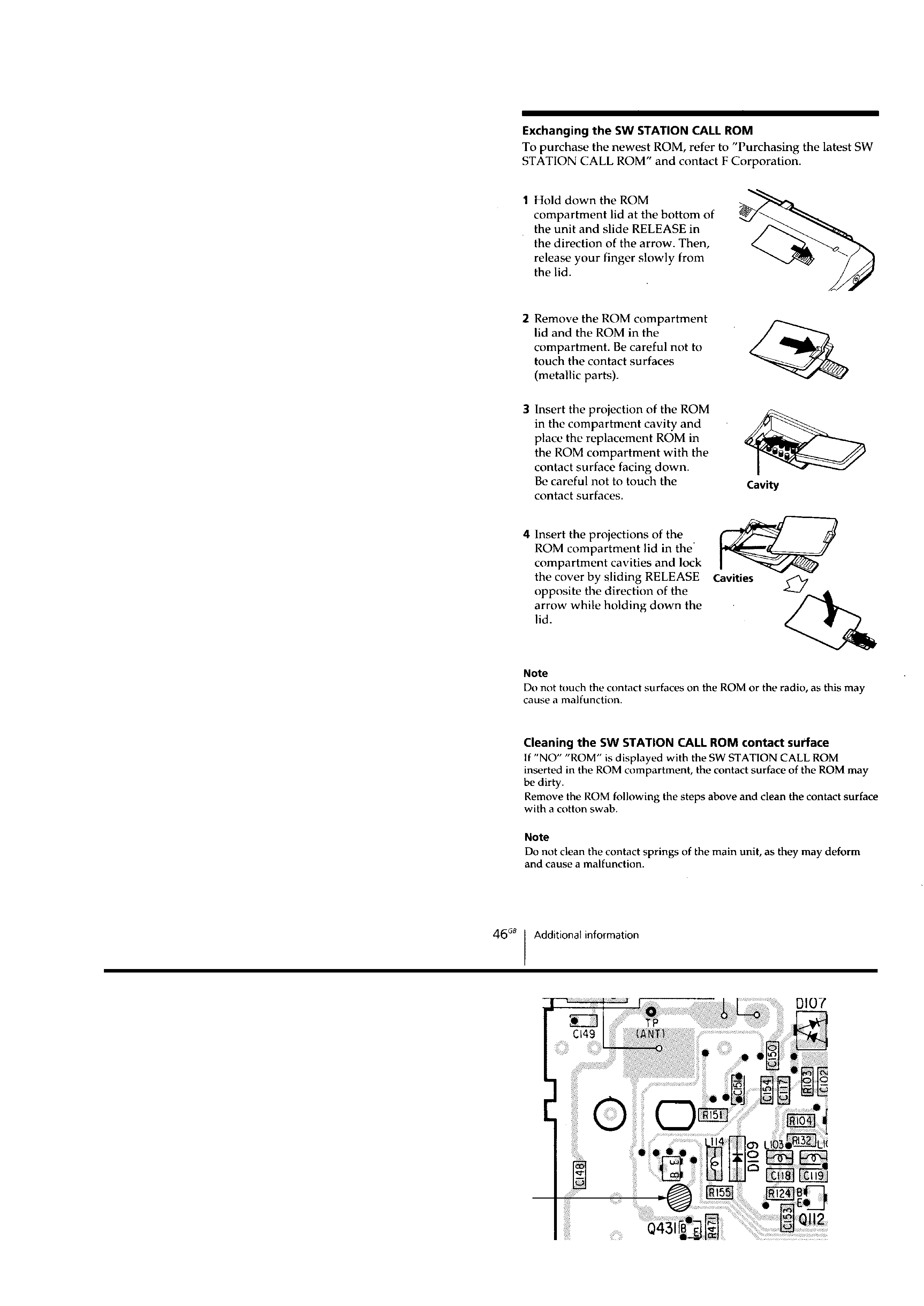
REPLACING THE SW STATION CALL ROM
The propagation of short-wave radio waves is greatly affected by
many causes such as atmospheric phenomenon due to dark spots on
the sun, etc.
This makes it necessary for short wave radio broadcast stations to
periodically change their broadcast frequencies. This set can be re-
placed with a new SW STATION CALL ROM to allow changing
the broadcast frequencies.
This set came with the latest ROM (Sony) when purchased. The
user can later on when needed, purchase the latest updated ROM (F
Corp.) version from the F Corporation on referring to the instruc-
tions for "Purchasing the Latest SW STATION CALL ROM" which
are included with the unit. These ROMs can also
be custom made to match the user's particular combination of broad-
cast station frequencies.
· Identify the 2 different types of ROMs (Sony or F Corp.) as
follows.
The Sony ROM has no printing on it.
The F Corp. ROM is marked with the F Corporation name.
· Servicing is provided for the accessory Sony ROM.
· Only the most recent version is supplied for replacing the Sony
ROM.
· A new updated Sony ROM is issued every year so is not usually
kept in stock.
· Servicing is not provided for the F Corp. ROM.
· Instruct the user to directly contact the F Corporation when the
F Corp. ROM is obviously malfunctioning or defective.
Address
Mail
: F Corporation P.O. Box 816
Tokyo 100-8692 Japan
Fax
: 81-3-3436-1932
E-mail : [email protected]
Q130
Short land
AEP, 7AEP model only
Connecting short land as in the figure when changed main board.
[MAIN BOARD] (SIDE A)
4
SECTION 2
GENERAL
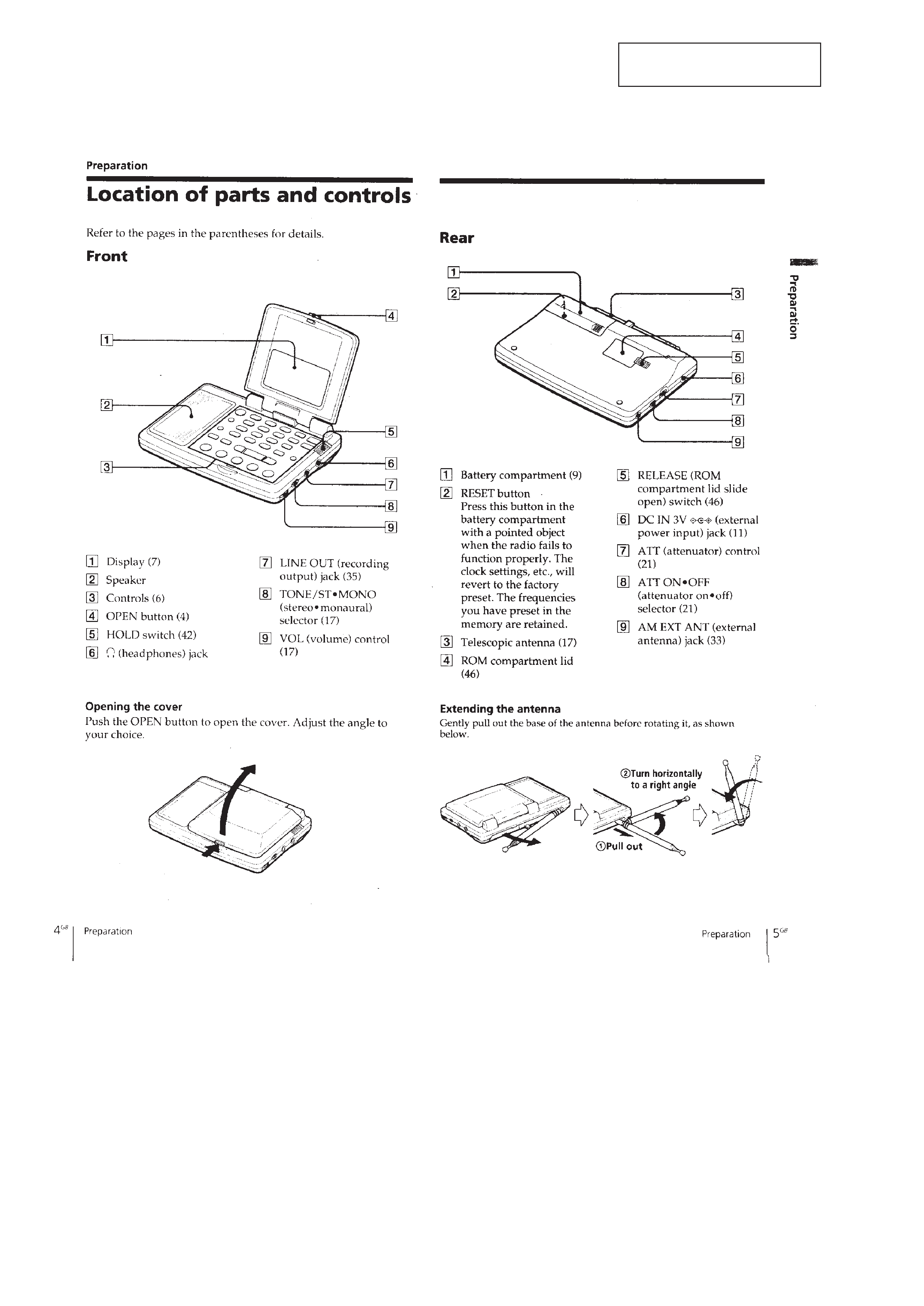
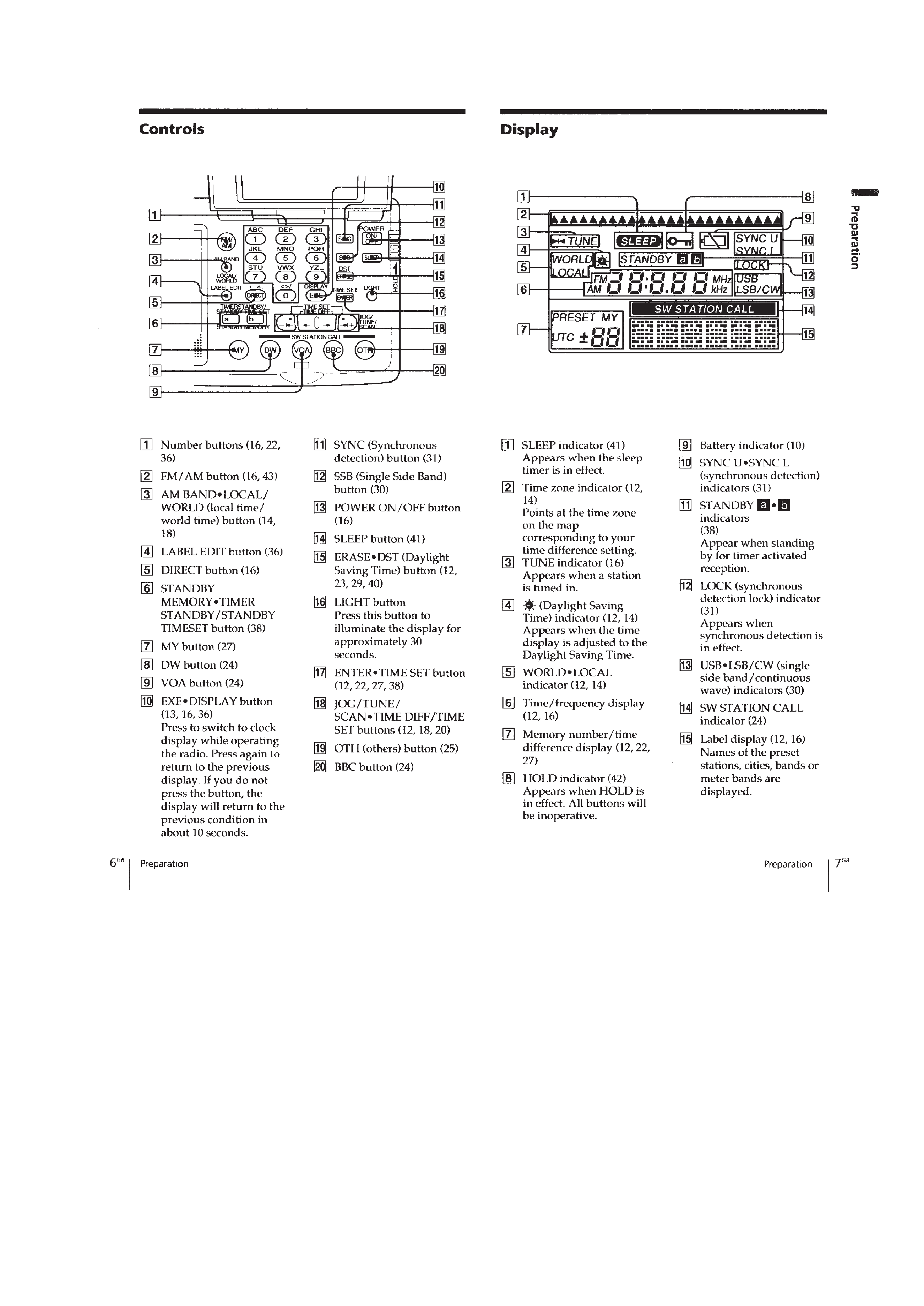
LOCATION AND FUNCTION OF CONTROLS
This section is extracted from
instruction manual.
5