SERVICE MANUAL
Ver 1.2 2002.02
9-925-738-12
Sony Corporation
2002B0500-1
Personal Audio Company
C
2002.02
Published by Sony Engineering Corporation
ICF-S79
FM/AM SYNTHESIZED RADIO
ICF-S79L
FM/MW/LW SYNTHESIZED RADIO
ICF-S79V
TV/WEATHER/FM/AM SYNTHESIZED RADIO
US Model
ICF-S79V
AEP Model
ICF-S79/S79L
UK Model
ICF-S79L
SPECIFICATIONS
ICF-S79/S79L/S79V
Photo: ICF-S79V (Original Type)
Frequency range:
Model for North and South America
Band
ICF-S79V
Channel step
FM
87.5 108 MHz
0.1 MHz
AM
530 1,710 kHz
10 kHz
TV
2 13 ch
--
WEATHER
1 5 ch
--
Model for other countries
Band
ICF-S79
ICF-S79L
Channel Step
FM
87.5 108 MHz
87.5 108 MHz
0.05 MHz*
AM(MW) 531 1,602 kHz 531 1,602 kHz
9 kHz
LW
--
153 279 kHz
9 kHz
* The frequency display is raised or lowered by steps of
0.1 MHz. For example, both 88.00 MHz and 88.05 MHz
will be displayed as "88.0 MHz."
Time display:
Model for North and South America: 12-hour
system
Model for other countries: 24-hour system
Speaker:
7.7 cm (3 1/8 inches), 8 ohms
Power output:
220 mW (at 10% harmonic distortion)
Power requirements:
4.5 V DC, three size C (R14) batteries
Dimensions: Approx. 143.5 x 139 x 67 mm
(w/h/d) (Approx. 5 3/4 x 5 1/2 x 2 3/4
inches) incl. projecting parts and controls
Mass: Approx. 523 g (1lb 2oz) incl. batteries
Supplied accessories: Suction cup (1), Strap (1)*
*North and South American model only
Design and specifications are subject to change
without notice.
Notes on chip component replacement
· Never reuse a disconnected chip component.
· Notice that the minus side of a tantalum capacitor may be dam-
aged by heat.
no mark : Original Type
Liv
: Liv Type
MODEL IDENTIFICATION
There are two types of ICF-S79V.
Please look at the mark of set shown below.
2
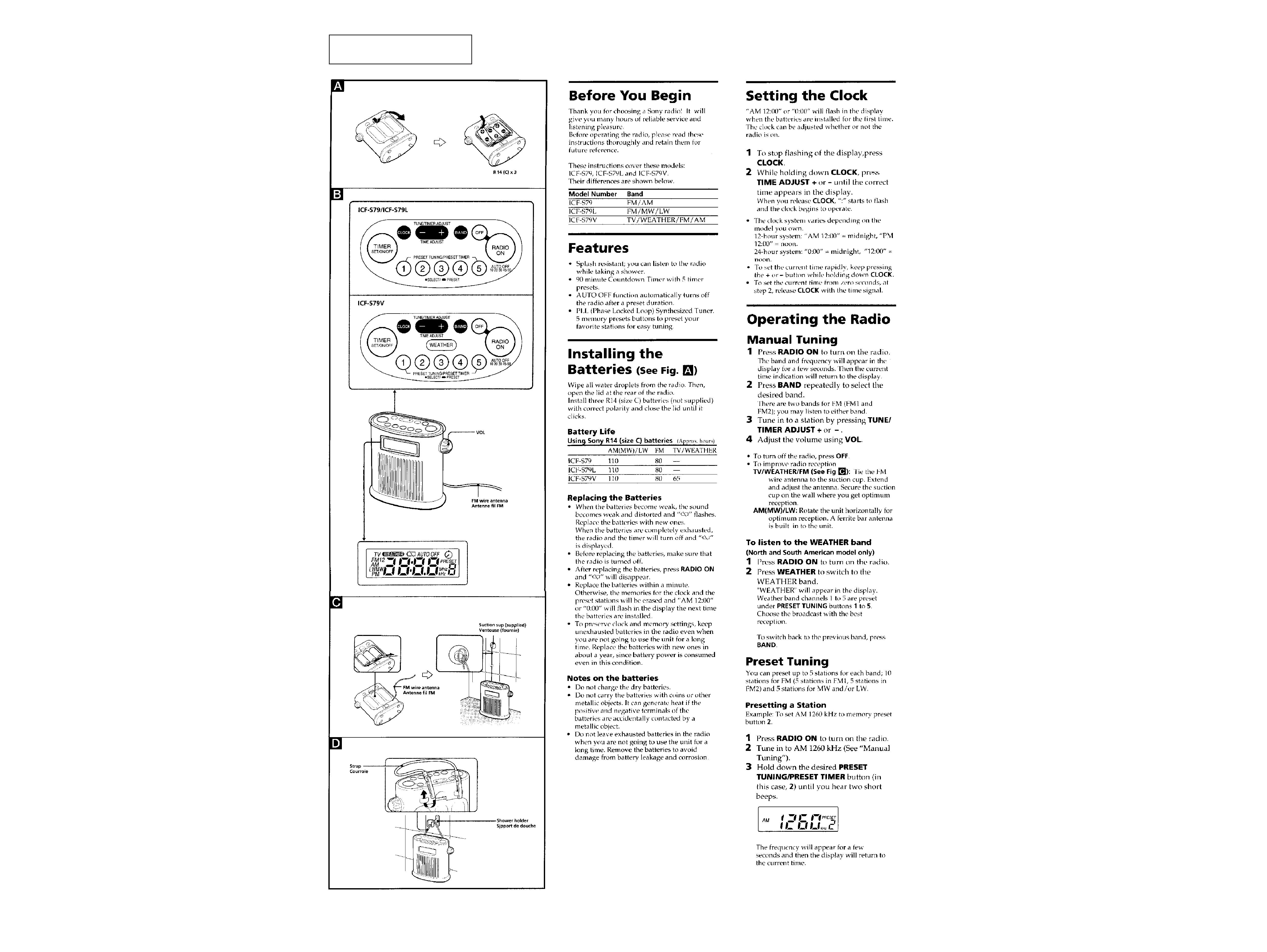
This section is extracted from
instruction manual.
SECTION 1
GENERAL
3
4
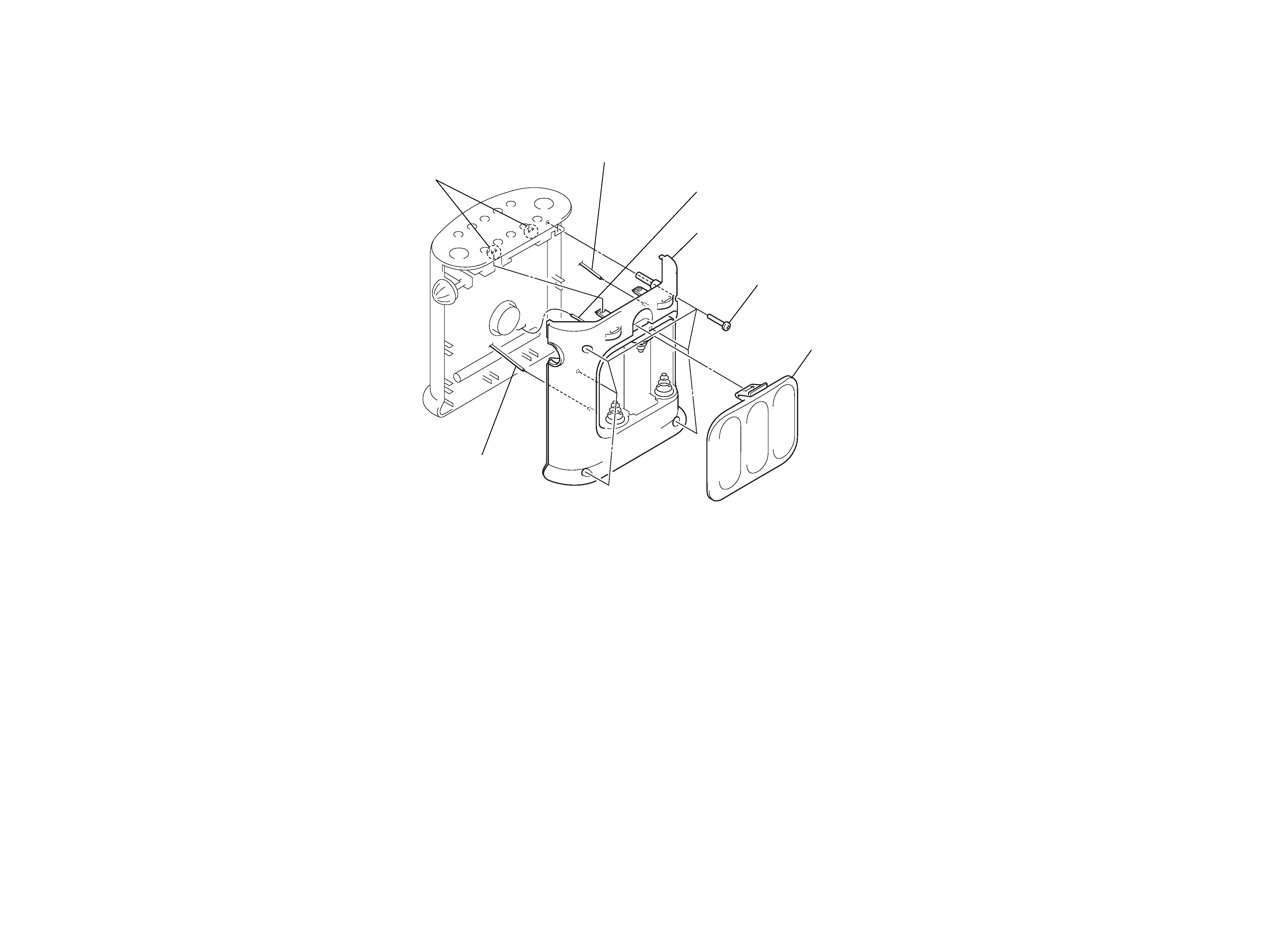
Note: Follow the disassembly procedure in the numerical order given.
REAR CABINET
SECTION 2
DISASSEMBLY
2 six screws
(BTP 3
× 25)
1 battery case lid
4 rear cabinet
5 antenna lead
5 BATT lead (red)
3 two claws
5 BATT lead (white)
FM FREQUENCY COVERAGE ADJUSTMENT
Adjust for a reading on digital voltmeter.
L8
87.5 MHz (TV 2 ch)
2.3 ± 0.1 V (1.0 ± 0.1 V)
Confirm
108.0 MHz
8.5 ± 0.5 V (12.5 ± 0.5 V)
Note: Not use the FM RF signal generator in this adjustment.
(
): ICF-S79V
FM TRACKING ADJUSTMENT
Adjust for a maximum reading on level meter.
L6
87.5 MHz (TV 2 ch (59.75 MHz))
CT4
108.0 MHz
(
): ICF-S79V
ICF-S79L only
LW FREQUENCY COVERAGE ADJUSTMENT
Adjust for a reading on digital voltmeter.
CT5
153 kHz
2.3 ± 0.1 V
Confirm
279 kHz
8.5 ± 0.5 V
Note: Not use the AM RF signal generator in this adjustment.
ICF-S79L only
LW TRACKING ADJUSTMENT
Adjust for a maximum reading on level meter.
L5 (LW side)
162 kHz
CT2
243 kHz
AM (MW) FREQUENCY COVERAGE ADJUSTMENT
Adjust for a reading on digital voltmeter.
L9
531 kHz (530 kHz)
2.8 ± 0.1 V
Confirm
1,602 kHz (1,710 kHz)
9.5 ± 0.5 V
Note: Not use the AM RF signal generator in this adjustment.
(
): ICF-S79V
AM (MW) TRACKING ADJUSTMENT
Adjust for a maximum reading on level meter.
L5 <MW side>
621 kHz (590 kHz)
CT3
1,395 kHz (1,490 kHz)
<
>: ICF-S79L
(
): ICF-S79V
AM IF ADJUSTMENT
Adjust for a maximum reading on level meter.
T2
455 kHz
5
6
Repeat the procedures in each adjustment several times, and the
frequency coverage and tracking adjustments should be finally done
by the trimmer capacitors.
SECTION 3
ELECTRICAL ADJUSTMENTS
[AM (LW/MW) Section]
Setting:
BAND switch: AM (MW) or LW
0dB=1 µV
[FM/TV Section]
Setting:
BAND switch: FM1 or TV
ICF-S79V only
TV FREQUENCY COVERAGE ADJUSTMENT
Adjust for a reading on digital voltmeter.
L2
WEATHER 2 ch
1.0 ± 0.1 V
Confirm
TV 13 ch
10 ± 0.5 V
Note: Not use the FM RF signal generator in this adjustment.
ICF-S79V only
TV TRACKING ADJUSTMENT
Adjust for a maximum reading on level meter.
L1
WEATHER 2 ch (162.40 MHz)
CT1
TV 13 ch (215.75 MHz)
ICF-S79V only
TV IF ADJUSTMENT
Adjust for a maximum reading on level meter.
T1
10.7 MHz
Adjustment and Connection Location:
AM RF SSG
30% amplitude
modulation by
400 Hz signal
Output level: as low as possible
Put the lead-wire
antenna close to
the set.
+
level meter
speaker terminal
set
FM RF SSG
± 22.5 kHz frequency
deviation by 400 Hz
signal
Output level: as low as possible
+
level meter
speaker terminal
set
FM lead wire antenna terminal
0.01
µF
FM antenna
ground
(JW17)
L8
FM FREQUENCY
COVERAGE
L9
AM (MW)
FREQUENCY
COVERAGE
L5
CT3
AM (MW)
TRACKING
TV TRACKING
(ICF-S79V only)
T1
TV IF
(ICF-S79V only)
L2
TV FREQUENCY
COVERAGE
(ICF-S79V only)
CT5
LW FREQUENCY
COVERAGE
(ICF-S79L only)
TV antenna
ground
(JW20)
FM/TV
antenna input
(JW18)
CT1
L1
T2
AM IF
FM
TRACKING
L6
CT4
CT2
L5
LW TRACKING
(ICF-S79L only)
MW
LW
L5
IC1
IC2
TP
(VT)
+
digital voltmeter
MAIN board
TP
(VT)
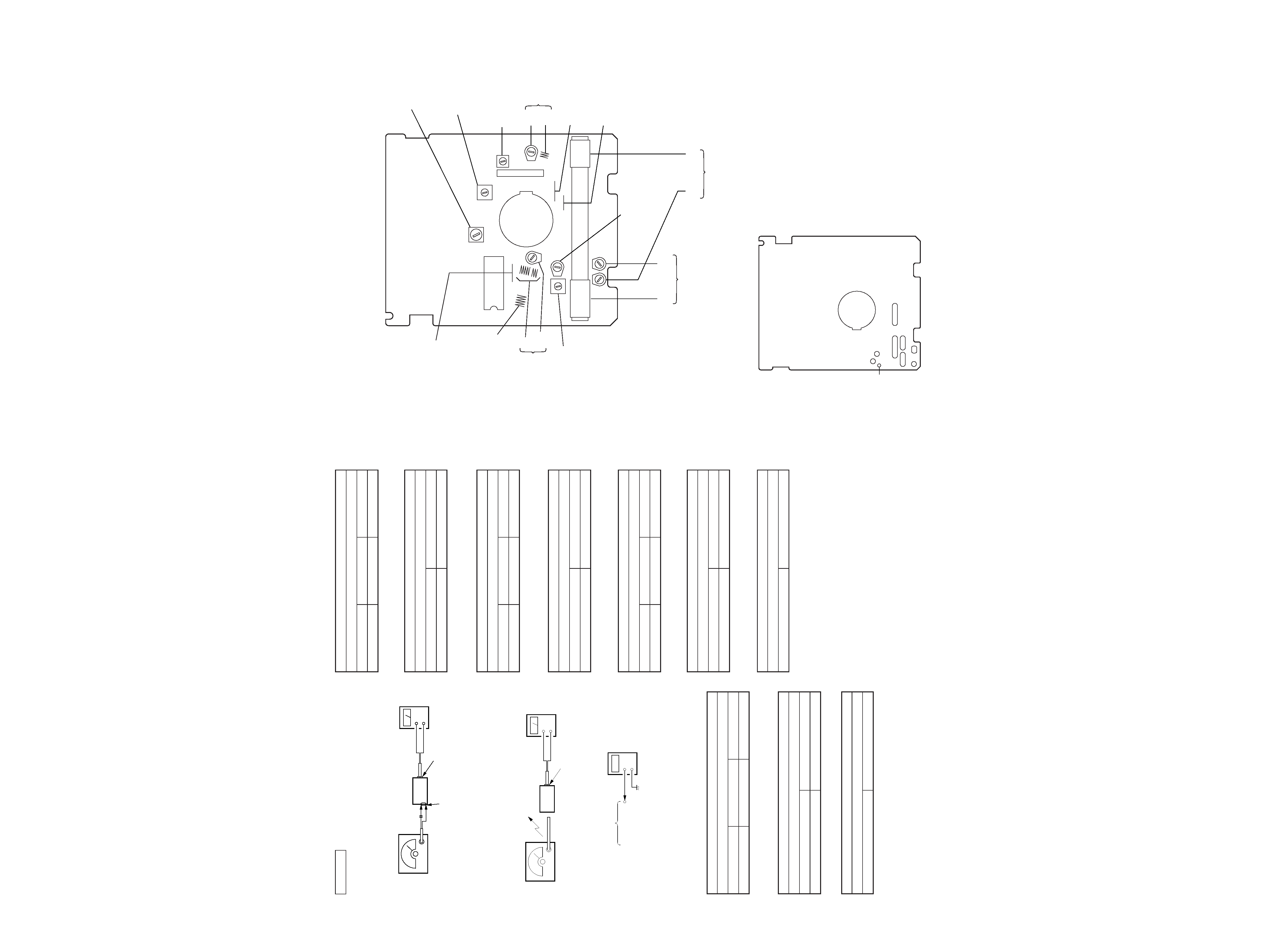
[MAIN BOARD] (Component Side)
[MAIN BOARD] (Conductor Side)