MICROFILM
SERVICE MANUAL
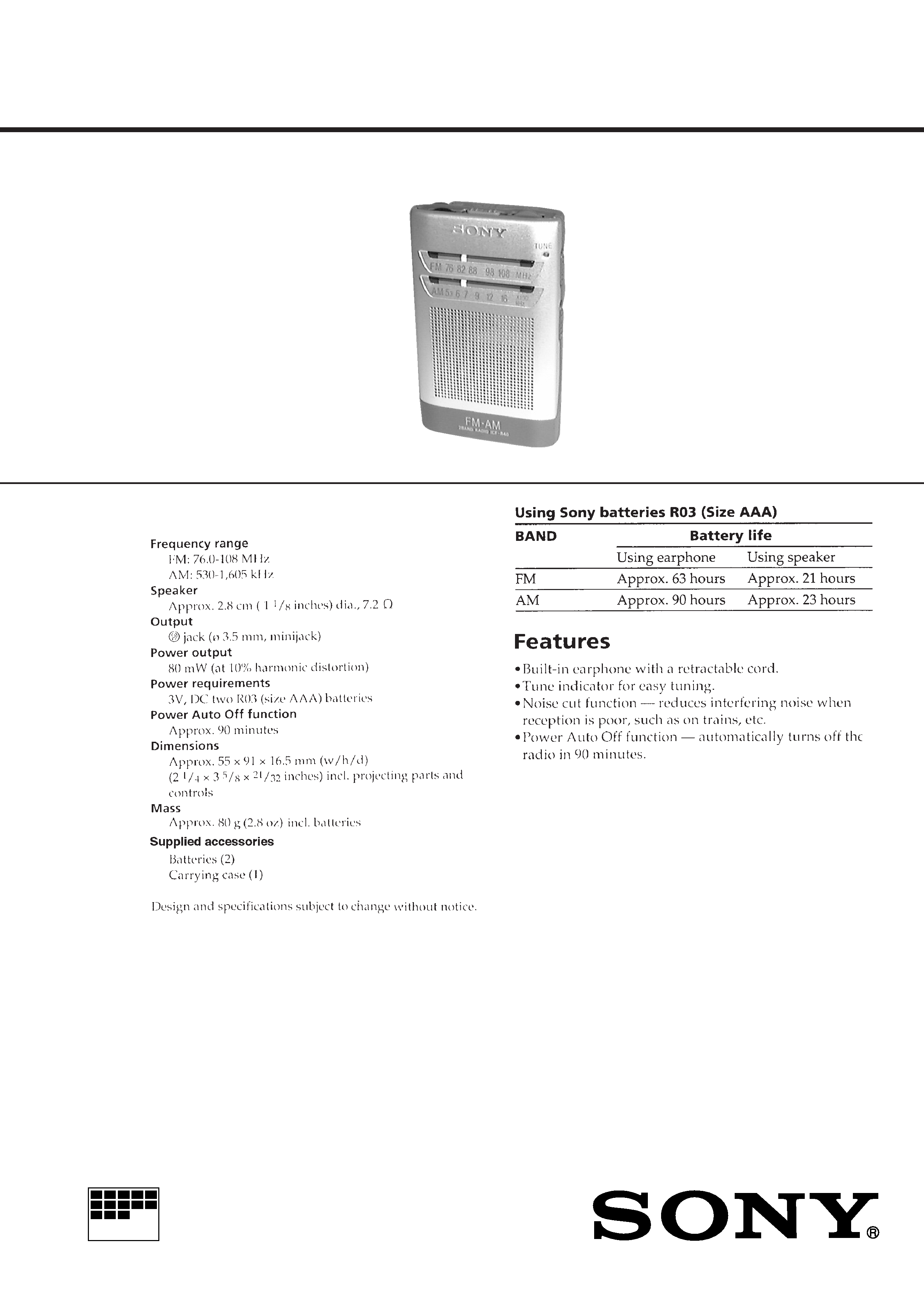
FM/AM RADIO
Tourist Model
SPECIFICATIONS
ICF-R40
Ver 1.0 1999. 03
2
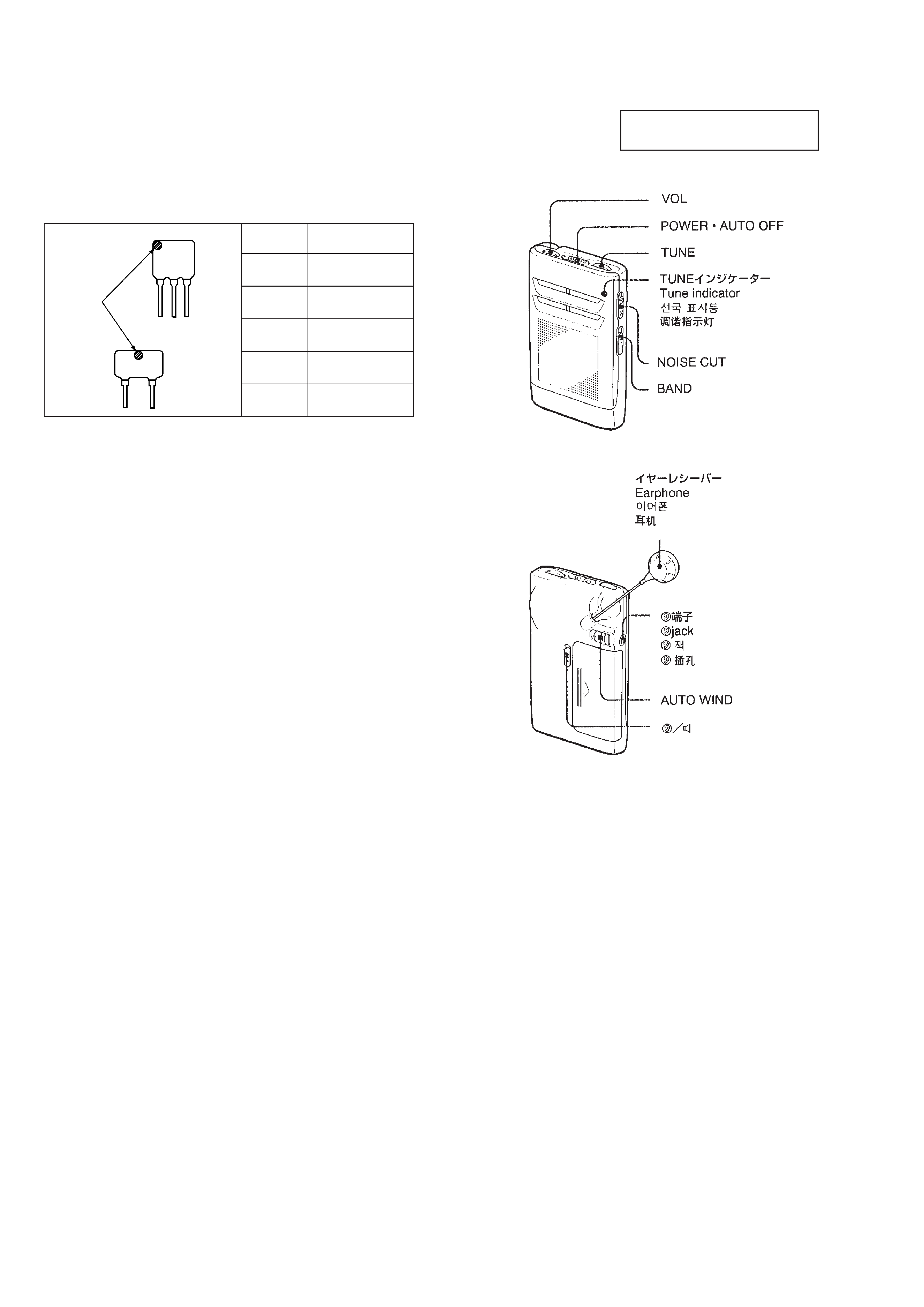
HOW TO CHANGED THE CERAMIC FILTERS
This model is used two ceramic filters of CF2 and CF3.
You must used same type of color marked ceramic filters in order
to meet same specifications.
Therefore, the ceramic filter must changed two pieces together
since it's supply two pieces in one package as a spare parts.
CF2
CF3
mark
Mark
Center frequency
red
10.70 MHz
blue
10.67 MHz
orange
10.73 MHz
black
10.64 MHz
white
10.76 MHz
Notes on chip component replacement
· Never reuse a disconnected chip component.
· Notice that the minus side of a tantalum capacitor may be dam-
aged by heat.
SECTION 1
GENERAL
This section is extracted from
instruction manual.
3
CABINET (REAR)
MAIN BOARD
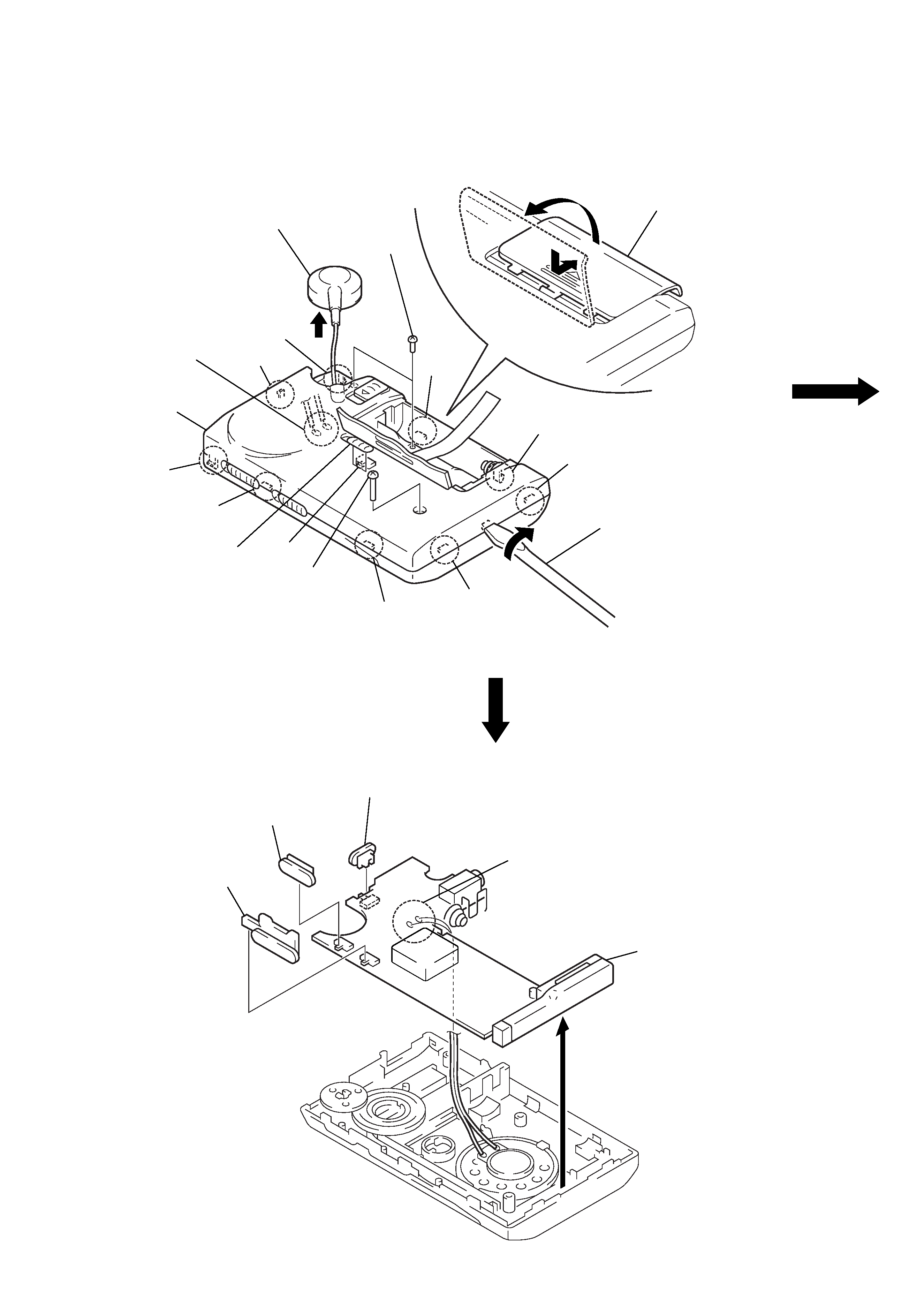
Note: Follow the disassembly procedure in the numerical order given.
SECTION 2
DISASSEMBLY
1 Pull out the ear receiver.
9 claw
3 two screws
(DIA. 1.4
× 4)
4 screw
(M1.7
× 10)
9 claw
8 claw
S1
6 claw
7 claw
6 claw
C
7 claw
2 Open the "lid, battery case"
in the direction of arrows
A to B.
5 First, insert the flat-blade screwdriver
into the cabinet and turn it in the direction
of the arrow
C to release two claws 6.
Next, release all claws from
7 to 0 in
numerical order.
Note: Hold a cloth to the cabinet
not to be damaged.
!¡ Remove two solders
of reel assy.
8 claw
knob
(earphone/spaeker)
!º claw
A
B
!TM cabinet (rear)
Note: On installation of cabinet (rear),
adjust the knob (earphone/speaker)
and S1.
3 knob (2 band)
2 knob (noise cut)
1 knob (power)
4 Remove two solders
of speaker leads.
5 MAIN board
4
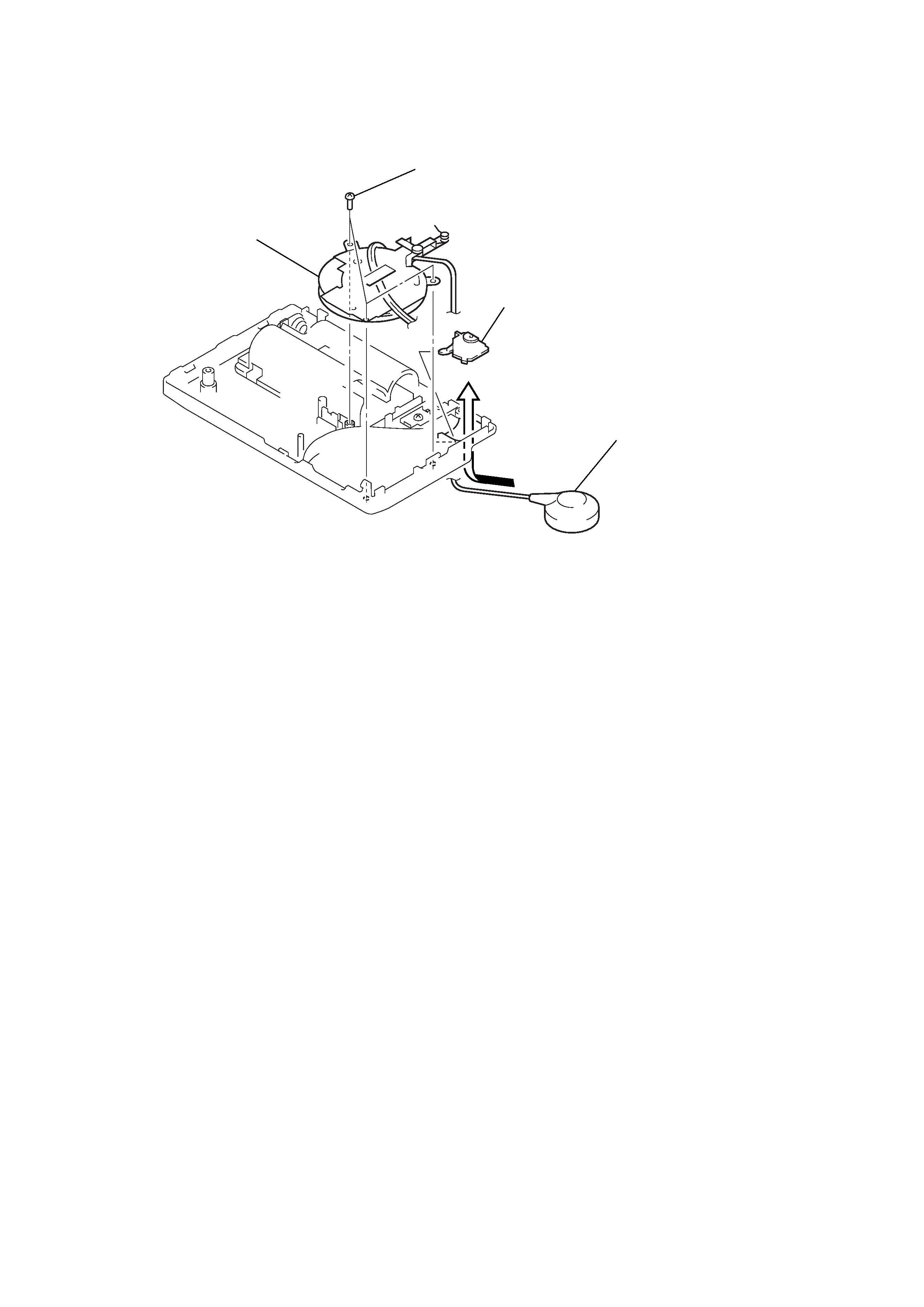
REEL ASSY
4 reel assy
2 three screws
(B1.4
× 3)
3 Draw the ear receiver
in the direction of the arrow.
1 blind plate
5
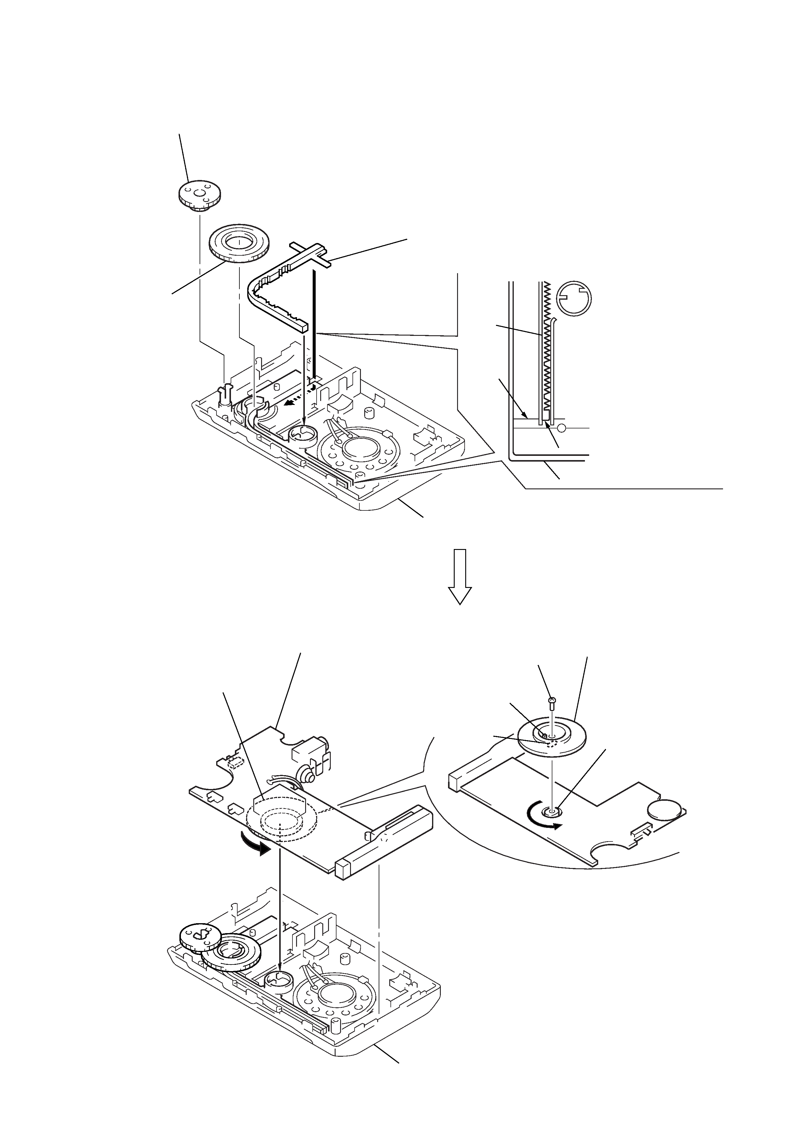
SECTION 3
DIAL POINTER SETTING
Note: Follow the assembly procedure in the numerical order given.
A
4 knob (tune)
1 Insert the pointer in the groove of
cabinet (front) assy and slide
in the direction of the arrow
A.
3 gear
(midway)
cabinet (front) assy
cabinet (front) assy
the tip of pointer
pointer
marking
2 Set the tip of pointer to the marking
of cabinet (front) assy.
8 Rotate the gear
(tuning capacitor) fully
in the direction of the arrow
C.
C
B
9 MAIN board
Note: On installation of MAIN board,
set the outline of gear
(tuning capacitor).
boss
oval
6 To install the gear
fixing each oval shape,
set the boss of the gear
(tuning capacitor) as the figure.
7 screw
(1.7
× 3)
5 Rotate the tuning capacitor
shaft fully in the direction of
the arrow
B.
cabinet (front) assy