MICROFILM
SERVICE MANUAL
FM/AM (LW) RDS RADIO
AEP Model
UK Model
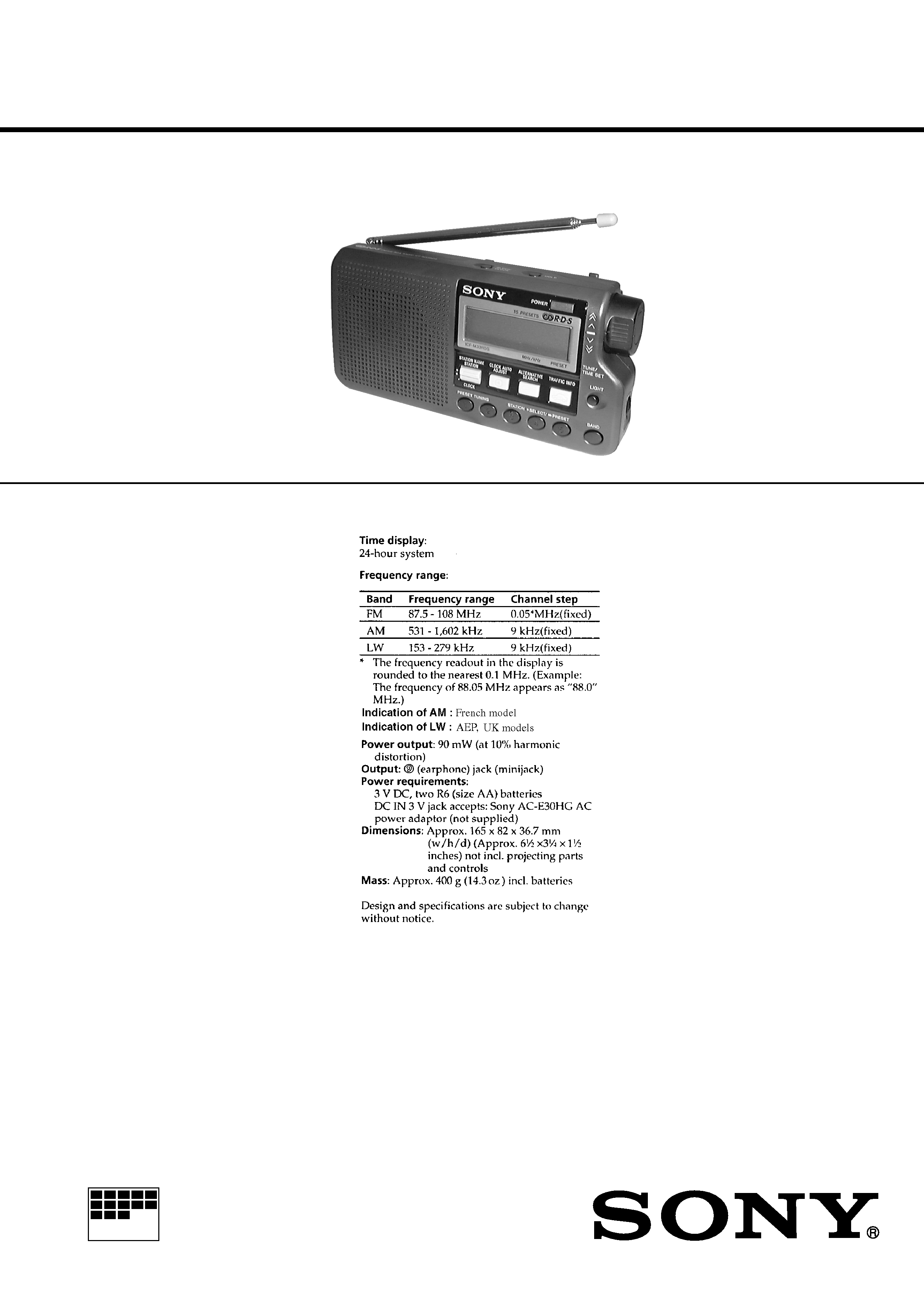
SPECIFICATIONS
ICF-M33RDS
Ver 1.2 2001.02
With SUPPLEMENT-1
(9-926-922-81)
2
TABLE OF CONTENTS
1.
GENERAL
Features ...........................................................................
3
Choosing the Power Source ............................................
4
Setting the Clock .............................................................
4
Operating the Radio ........................................................
4
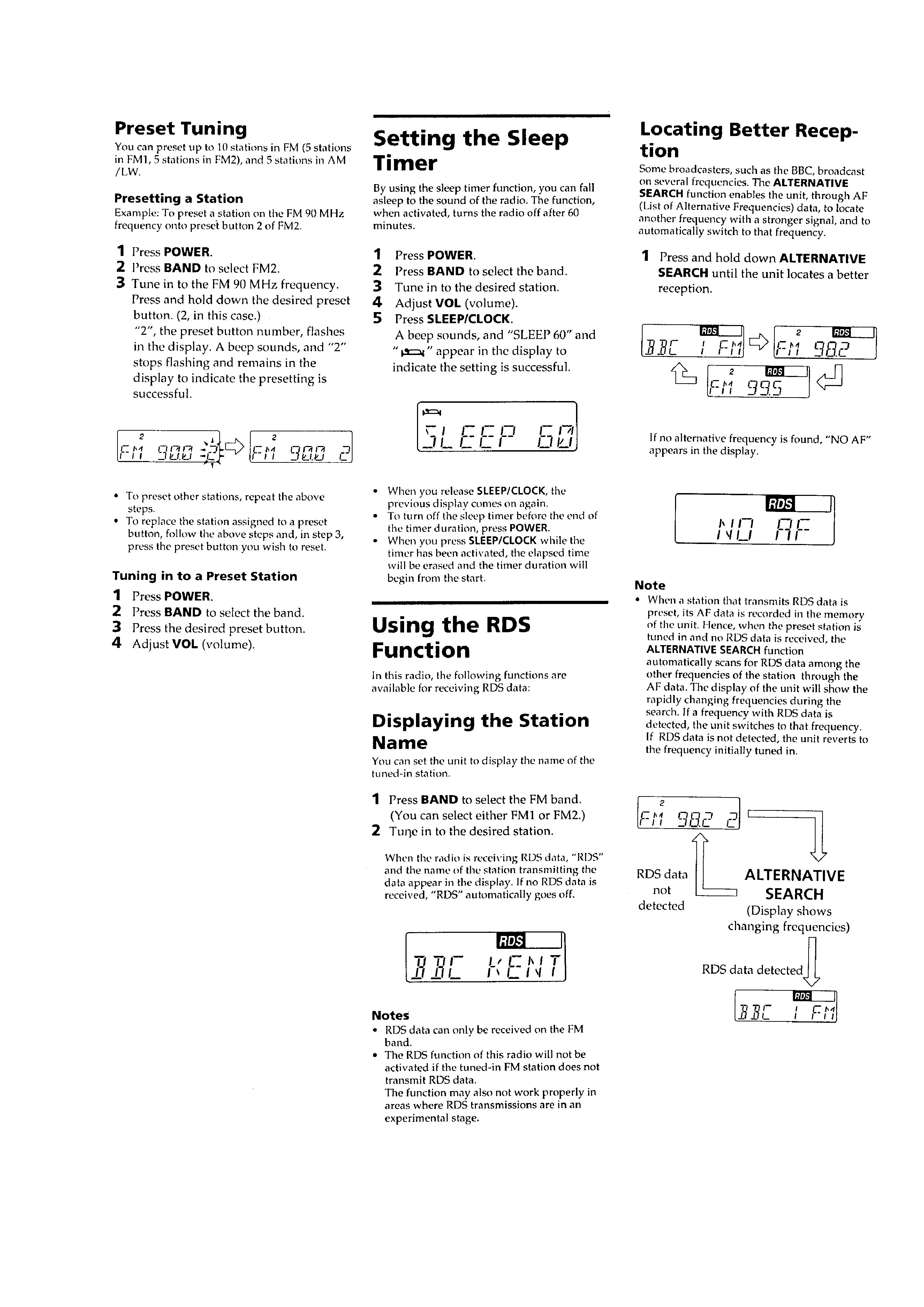
Setting the Sleep Timer ...................................................
5
Using the RDS Function .................................................
5
Using Other Functions ....................................................
6
Precautions ......................................................................
6
2.
DISASSEMBLY ......................................................... 7
3.
ELECTRICAL ADJUSTMENTS ......................... 9
4.
DIAGRAMS
4-1. Block Diagram ................................................................ 11
4-2. Note for Printed Wiring Boards and
Schematic Diagrams ....................................................... 13
4-3. Printed Wiring Board MAIN Section ...................... 14
4-4. Printed Wiring Board PANEL Section .................... 17
4-5. Schematic Diagram ......................................................... 21
4-6. IC Pin Function Description ........................................... 28
5.
EXPLODED VIEW ................................................... 29
6.
ELECTRICAL PARTS LIST ............................... 30
SERVICING NOTES
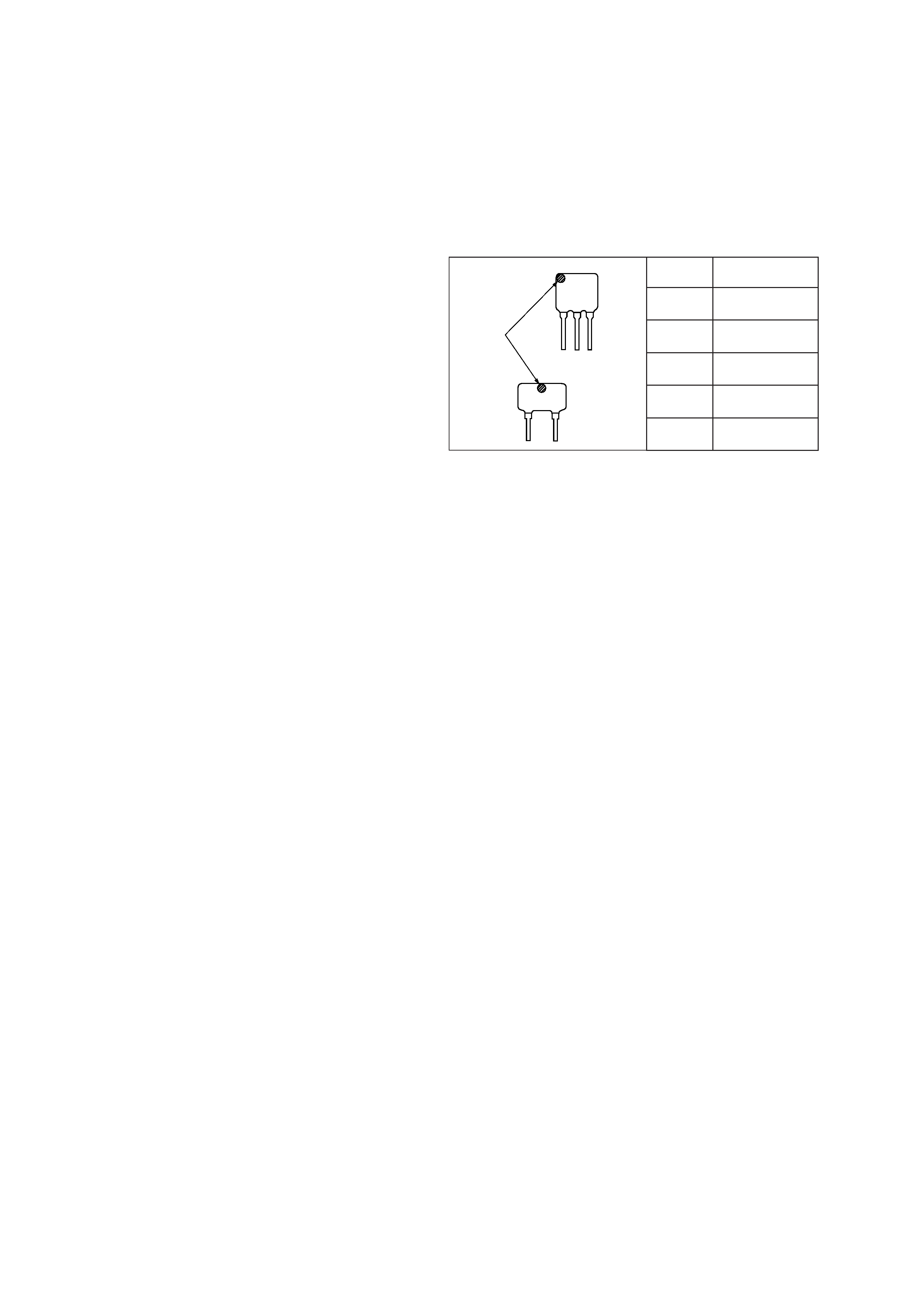
HOW TO CHANGED THE CERAMIC FILTERS
This model is used two ceramic filters of CF2 and CF3.
You must used same type of color marked ceramic filters in order
to meet same specifications.
Therefore, the ceramic filter must changed two pieces together
since it's supply two pieces in one package as a spare parts.
CF2
CF3
mark
Mark
Center frequency
red
10.70 MHz
blue
10.67 MHz
orange
10.73 MHz
black
10.64 MHz
white
10.76 MHz
Notes on chip component replacement
· Never reuse a disconnected chip component.
· Notice that the minus side of a tantalum capacitor may be dam-
aged by heat.
3
SECTION 1
GENERAL
This section is extracted from
instruction manual.
4
5