ICF-F1
AEP Model
SERVICE MANUAL
FM/AM RADIO
SPECIFICATIONS
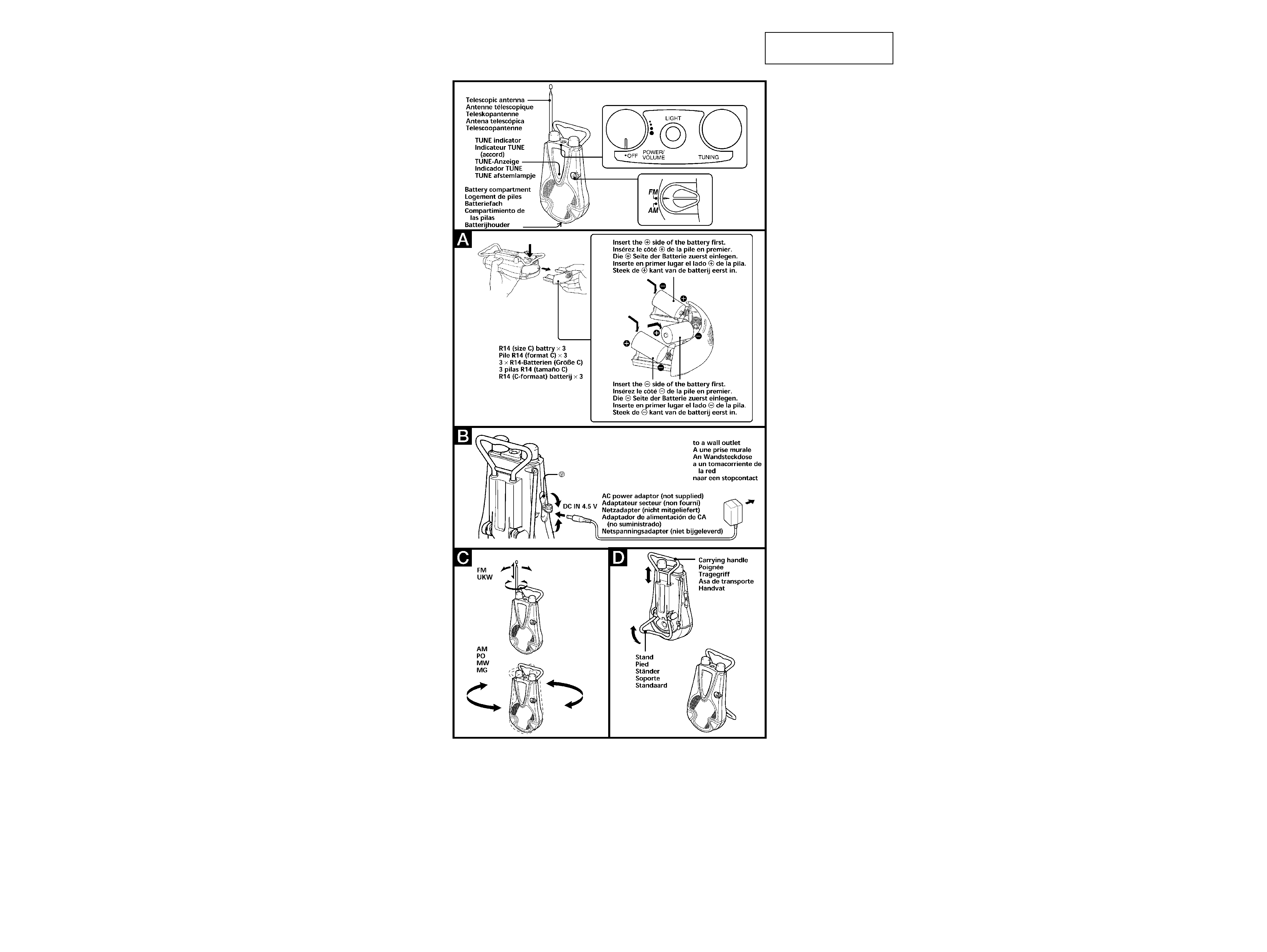
Frequency range:
FM : 87.5 - 108 MHz
AM : 526.5 - 1 606.5 kHz
Speaker
Approx. 10.0 cm (4 inches) dia., 8
Output
v
(earphone) jack (ø 3.5 mm minijack)
Power output
250 mW (at 10 % harmonic distortion)
Power requirements
4.5V DC, three R14 (size C) batteries
DC IN 4.5V jack accepts: Sony AC-E45HG AC
power adaptor (not supplied)
Dimensions
Approx. 130
× 237 × 71.5 mm (w/h/d)
(5 1/
8 × 9
3/
8 × 2
7/
8 inches) incl. projecting parts
and controls
Mass
Approx. 673.5 g (1 lb 8 oz) incl. batteries
Design and specifications are subject to change without notice.
Ver 1.0 2000. 05
-- 2 --
Notes on chip component replacement
· Never reuse a disconnected chip component.
· Notice that the minus side of a tantalum capacitor may be
damaged by heat.
Flexible Circuit Board Repairing
· Keep the temperature of soldering iron around 270°C
during repairing.
· Do not touch the soldering iron on the same conductor of the
circuit board (within 3 times).
· Be careful not to apply force on the conductor when soldering
or unsoldering.
SECTION 1
GENERAL
This section is extracted
from instruction manual.
-- 3 --
SECTION 2
DISASSEMBLY
Note :
Disassemble the unit in the order as shown below.
Cabinet (rear) assy
Set
Chassis assy
Speaker (SP1)
Vol board
Main board
Note :
Follow the disassembly procedure in the numerical order given.
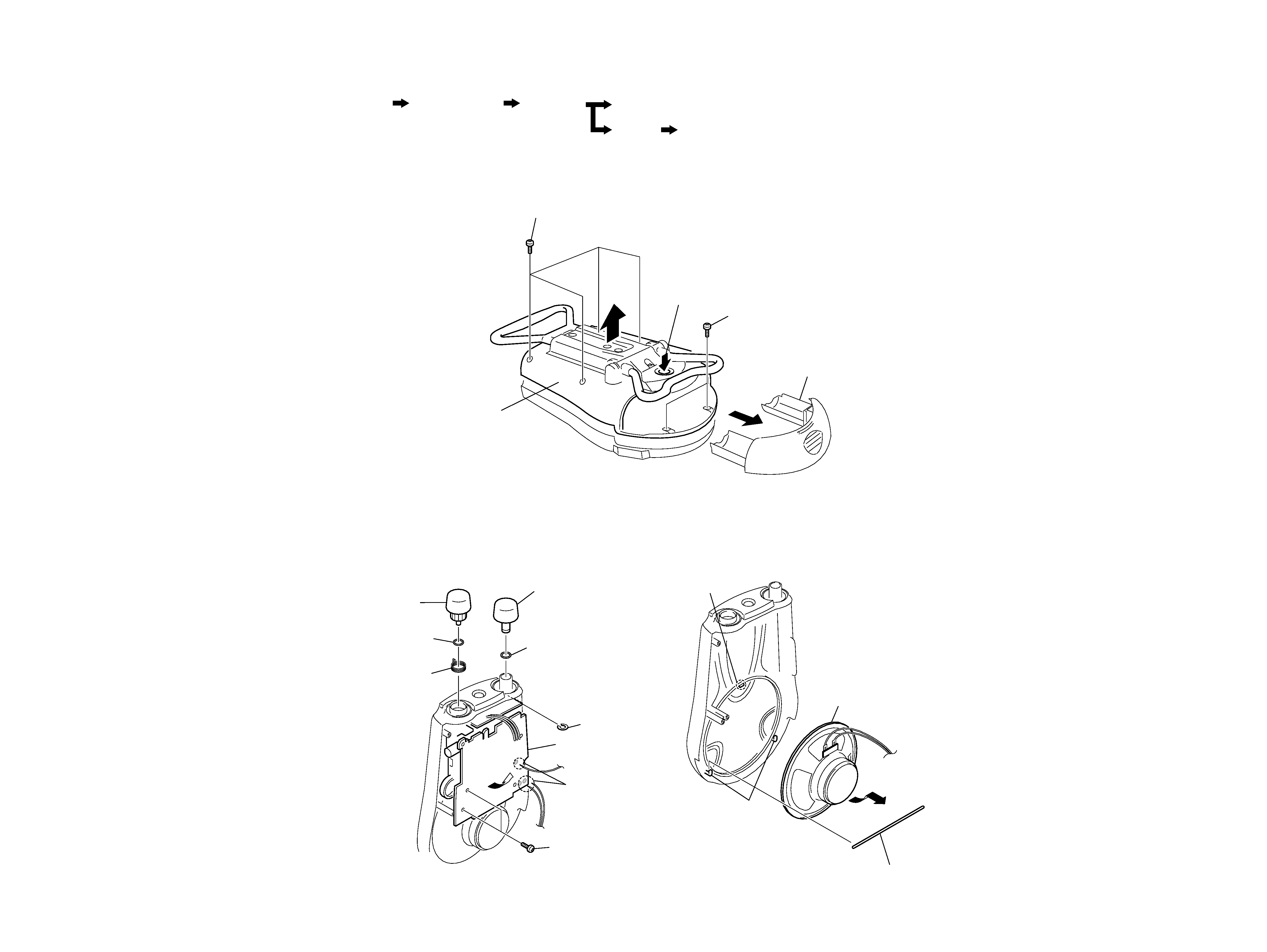
2-1. CABINET (REAR) ASSY
5
4 Four screws (+BTP 3
× 12)
3 Two screws (+BTP 3
× 12)
1 Push the knob (Battery box).
2 Box, battery
Cabinet (rear) assy
9
8 Two screws
(+P 2.6
× 8)
7 Remove
solderings
Chassis assy
5 Knob (vol)
1 Knob
(tune)
2 O ring
(DIA 12.5)
6 O ring (vol)
4 E ring
3 Spring,
ring
3 Speaker (10 cm)(SP1)
Claw
Two claws
1 Spring, SP detent
2
2-2. CHASSIS ASSY
2-3. SPEAKER (SP1)
-- 4 --
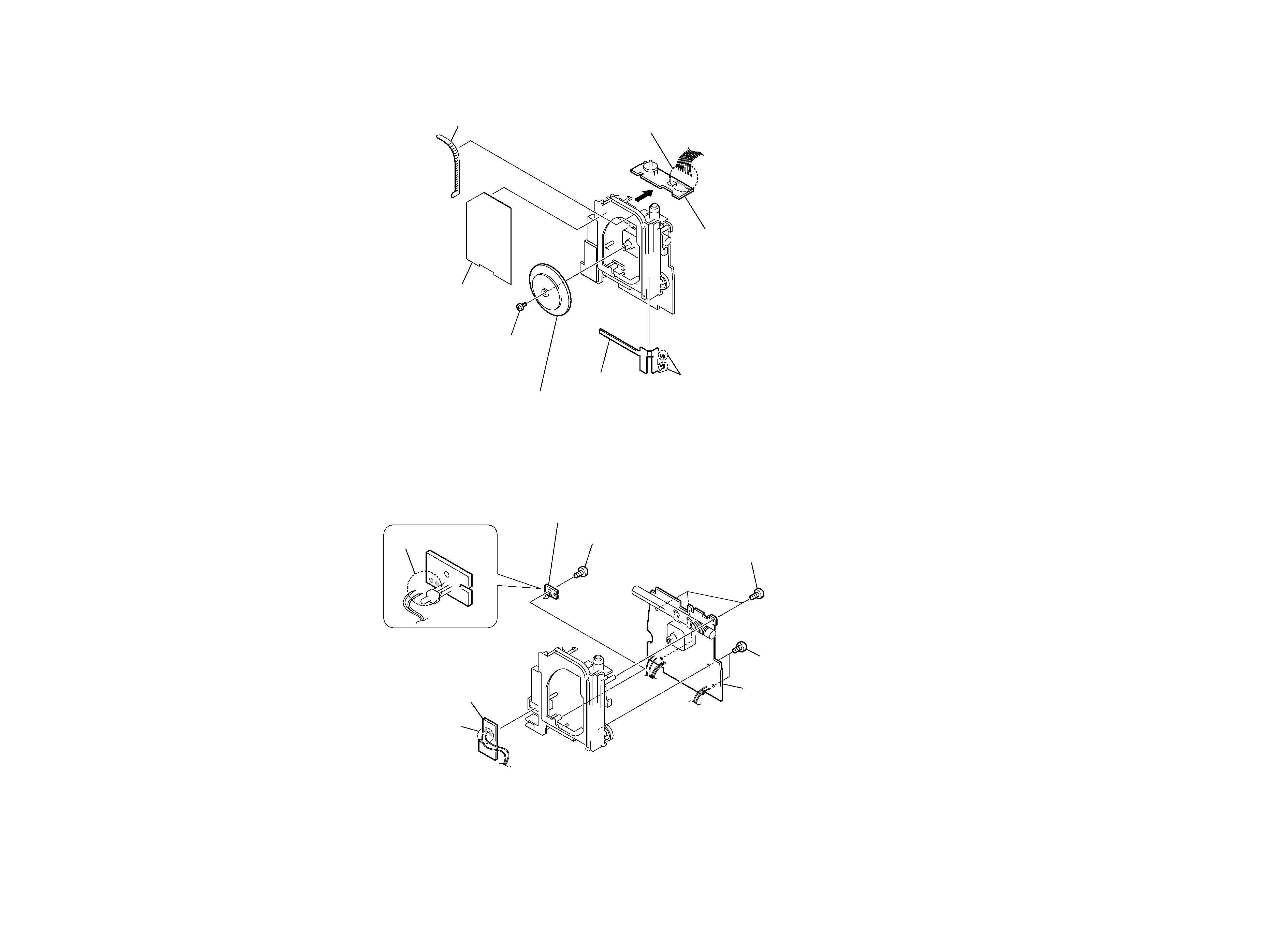
2-4. VOL BOARD
7 Screw
(+P2.6
× 8)
Two claws
4 Pointer
5 Scale, dial
6 Rack
3 Vol board
1
8 Gear (A), tuning capacitor
2 Remove solderings
2-5. MAIN BOARD ASSY
1 Remove solderings
7 Remove solderings
5 Main board
8 LED board
2 Jack board
4 Two screws (+P 2.6
× 8)
6 Screw (+P 2.6
× 8)
3 Three screws (+BTP 3
× 12)
SECTION 3
ELECTRICAL ADJUSTMENTS
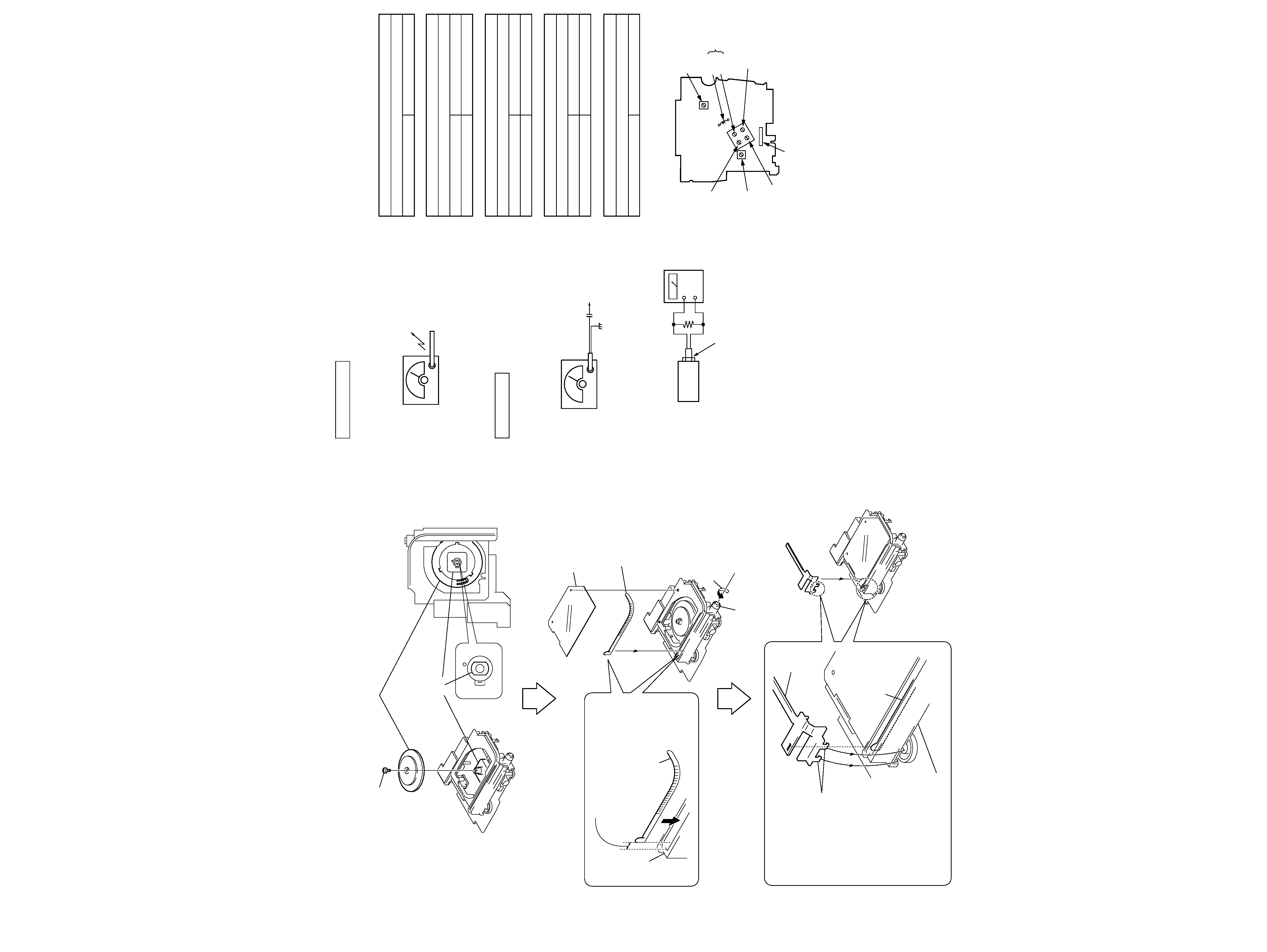
2-6. DIAL POINTER
-- 5 --
-- 6 --
Screw
CV1
1mm
Chassis
Chassis
4 Scale, dial
Rack
Shaft (tune)
2 Rotate the Shaft (tune)
in the direction of the arrow fully.
1 Install the tuning capacitor gear (A) in the direction
as shown while it is aligned with CV1.
Rack
Rack
Pointer
Two claws
3 Push the rack deep inside at the position
of 1 mm away from the end surface
of the Chassis as far as it can go.
5 Attach the pointer as follows
: While aligning the hole of the
pointer with the projection
of the rack, engage the two
claws of the pointer with
the chassis.
BAND : AM
Signal generator
· Repeat the procedures in each adjustment several times for the
maximum level meter indication.
· The frequency coverage and tracking adjustments should be finally
done by the trimmer capacitors.
AM SECTION
FM SECTION
[Adjustment Location : Main board] (Component side)
Put the lead-wire
antenna close to
the set.
30% amplitude modulation by 400Hz
signal.
Output level : as low as possible
AM RF signal
generator
0.01
µF
FM RF signal
generator
telescopic
antenna
terminal
75kHz (100%) amplitude modulation
by 1kHz signal.
Output level : as low as possible
16
set
+
level meter
Speaker terminal (SP1)
AM IF ADJUSTMENT
Adjust for a maximum reading on level meter.
T1
455 kHz
AM TRACKING ADJUSTMENT
Adjust for a maximum reading on level meter.
L1
600 kHz
CT1-1
1,400 kHz
FM TRACKING ADJUSTMENT
Adjust for a maximum reading on level meter.
L3
87.35 MHz
CT1-2
108.25 MHz
AM FREQUENCY COVERAGE ADJUSTMENT
Adjust for a maximum reading on level meter.
L5
516.5 kHz
CT1-4
1,631.5 kHz
FM FREQUENCY COVERAGE ADJUSTMENT
Adjust for a maximum reading on level meter.
CT1-3
108.25 MHz
BAND : FM
Signal generator
L3
CT1-2
FM
TRACKING
adjustment
T1
AM IF
adjustmnet
CT1-4
AM
FREQUENCY
COVERAGE
adjustment
CT1-3
FM
FREQUENCY
COVERAGE
adjustment
L5
AM
FREQUENCY
COVERAGE
adjustment
CT1-1
AM TRACKING
adjustment
L1 AM TRACKING adjustment