SERVICE MANUAL
AUDIO POWER SPECIFICATIONS
POWER OUTPUT AND TOTAL HARMONIC
DISTORTION
With 3.2ohm loads, both channels driven from
150 10 000 Hz; rated 0.8 W per channel-minimum
RMS power, with no more than 10 %
total harmonic distortion in AC operation.
Woofer with 3.2ohm loads, driven at 50 150
Hz; rated 3.2 W minimum RMS power, with no
more 10 % total harmonic distortion in AC
operation.
CD player section
System: Compact disc digital audio system
Laser diode properties: Material: GaAlAs
Wavelength: 780 nm
Emission duration: Continuous
Laser output: Less than 44.6 µW
(This output is the value measured at a
distance of about 200 mm from the objective
lens surface on the optical pick-up block with
7 mm aperture.)
Frequency response: 20-20 000 Hz
+1 dB
Wow and flutter: Below measurable limit
1.5
Radio section
Frequency range:
TV: 2 13 ch
WEATHER: 1 7 ch
FM: 87.5 108 MHz
AM: 530 1 710 kHz
General
Time display: 12-hour system
Speaker:
Front speaker: 80 mm (3 1/8 inches) dia. ×2, 3.2
Woofer: 82 mm (3 1/4 inches) dia., 3.2
Outputs: i (headphones) jack (ø 3.5 mm stereo minijack)
Power outputs:
Front speaker: 2.6W + 2.6W (at Max power out)
Woofer: 3.2 W
Power requirements: 120 V AC, 60 Hz
Dimensions:
Approx. 185 × 195 × 196 mm (w/h/d)
(Approx. 7 3/8 × 7 3/4 × 7 3/4 inches) incl.
projecting parts and controls
Mass: Approx. 2 700 g (5 lb 15 oz)
Design and specifications are subject to change
without notice.
TV/WEATHER/FM/AM CD CLOCK RADIO
US Model
SPECIFICATIONS
ICF-CD863V
Ver 1.1 2002.07
9-873-659-02
Sony Corporation
2002G0500-1
Personal Audio Company
C
2002.07
Published by Sony Engineering Corporation
Model Name Using Similar Mechanism
CFD-E75
CD Mechanism Type
KSM-213RDP
Optical Pick-up Name
KSS-213R
2
ICF-CD863V
About CD-Rs/CD-RWs
This unit is compatible with CD-Rs/CD-RWs but
playback capability may vary depending on the
quality of the disc, the recording device and
application software.
TABLE OF CONTENTS
1.
SERVICING NOTES ..............................................
3
2.
GENERAL ..................................................................
4
3.
DISASSEMBLY
3-1. Disassembly Flow ...........................................................
5
3-2. Cabinet (Rear) Section ....................................................
6
3-3. Cabinet (Upper) Section .................................................
6
3-4. Panel (SP) (,L), Panel (SP) (,R) ......................................
7
3-5. CD Lid Assy ....................................................................
7
3-6. KEY Board, MAIN Board ..............................................
8
3-7. CD Block .........................................................................
8
3-8. Optical Pick-up Device (KSS-213R) ..............................
9
3-9. TRANSFORMER Board ................................................
9
3-10. Box (SP) Assy ................................................................. 10
3-11. Speaker (8.2 cm) (Woofer) (SP301), Box (SP) .............. 11
4.
ELECTRICAL ADJUSTMENTS
Tuner Section ................................................................. 12
CD Section ..................................................................... 14
5.
DIAGRAMS
5-1. Block Diagram CD Section .................................... 15
5-2. Block Diagram TUNER Section ............................ 16
5-3. Block Diagram MAIN Section ............................... 17
5-4. Note for Printed Wiring Board and
Schematic Diagrams ....................................................... 18
5-5. Printed Wiring Board CD Section .......................... 20
5-6. Schematic Diagram CD Section ............................. 21
5-7. Printed Wiring Boards MAIN Section ................... 22
5-8. Schematic Diagram MAIN Section ........................ 23
5-9. Printed Wiring Boards POWER Section ................ 24
5-10. Schematic Diagram POWER Section .................... 25
5-11. Printed Wiring Boards PANEL Section ................. 26
5-12. Schematic Diagram PANEL Section ...................... 27
5-13. IC Pin Function Description .......................................... 30
6.
EXPLODED VIEWS
6-1. Overall Section ................................................................ 31
6-2. Cabinet (Front) Section ................................................... 32
6-3. Cabinet (Upper) Section ................................................. 33
6-4. Cabinet (Rear) Section .................................................... 34
6-5. Optical Block (KSM-213RDP) ....................................... 35
7.
ELECTRICAL PARTS LIST .............................. 36
SAFETY-RELATED COMPONENT WARNING!!
COMPONENTS IDENTIFIED BY MARK 0 OR DOTTED
LINE WITH MARK 0 ON THE SCHEMATIC DIAGRAMS
AND IN THE PARTS LIST ARE CRITICAL TO SAFE
OPERATION. REPLACE THESE COMPONENTS WITH
SONY PARTS WHOSE PART NUMBERS APPEAR AS
SHOWN IN THIS MANUAL OR IN SUPPLEMENTS PUB-
LISHED BY SONY.
Notes on chip component replacement
·Never reuse a disconnected chip component.
· Notice that the minus side of a tantalum capacitor may be dam-
aged by heat.
SAFETY CHECK-OUT
After correcting the original service problem, perform the follow-
ing safety check before releasing the set to the customer:
Check the antenna terminals, metal trim, "metallized" knobs,
screws, and all other exposed metal parts for AC leakage.
Check leakage as described below.
LEAKAGE TEST
The AC leakage from any exposed metal part to earth ground and
from all exposed metal parts to any exposed metal part having a
return to chassis, must not exceed 0.5 mA (500 microamperes).
Leakage current can be measured by any one of three methods.
1. A commercial leakage tester, such as the Simpson 229 or RCA
WT-540A. Follow the manufacturers' instructions to use these
instruments.
2. A battery-operated AC milliammeter. The Data Precision 245
digital multimeter is suitable for this job.
3. Measuring the voltage drop across a resistor by means of a
VOM or battery-operated AC voltmeter. The "limit" indica-
tion is 0.75 V, so analog meters must have an accurate low-
voltage scale. The Simpson 250 and Sanwa SH-63Trd are ex-
amples of a passive VOM that is suitable. Nearly all battery
operated digital multimeters that have a 2 V AC range are suit-
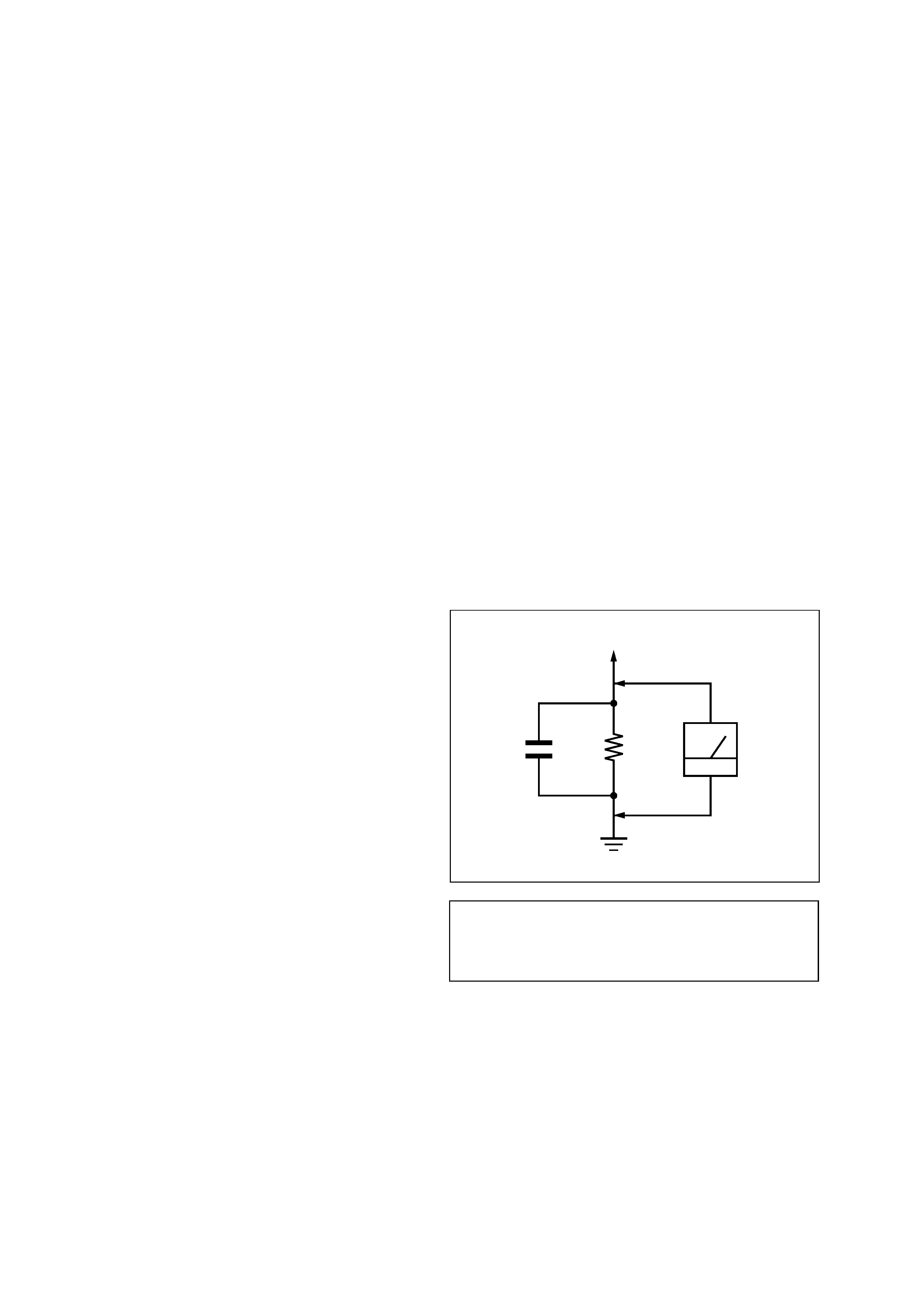
able. (See Fig. A)
Fig. A.
Using an AC voltmeter to check AC leakage.
1.5 k
0.15 µF
AC
voltmeter
(0.75 V)
To Exposed Metal
Parts on Set
Earth Ground
CAUTION
Use of controls or adjustments or performance of procedures
other than those specified herein may result in hazardous ra-
diation exposure.
3
ICF-CD863V
S301
SECTION 1
SERVICING NOTES
The laser diode in the optical pick-up block may suffer electro-
static break-down because of the potential difference generated
by the charged electrostatic load, etc. on clothing and the human
body.
During repair, pay attention to electrostatic break-down and also
use the procedure in the printed matter which is included in the
repair parts.
The flexible board is easily damaged and should be handled with
care.
NOTES ON LASER DIODE EMISSION CHECK
The laser beam on this model is concentrated so as to be focused
on the disc reflective surface by the objective lens in the optical
pick-up block. Therefore, when checking the laser diode emis-
sion, observe from more than 30 cm away from the objective lens.
LASER DIODE AND FOCUS SEARCH OPERATION
CHECK
During normal operation of the equipment, emission of the laser
diode is prohibited unless the upper lid is closed while turning ON
the S301. (push switch type)
The following checking method for the laser diode is operable.
· Method
Emission of the laser diode is visually checked.
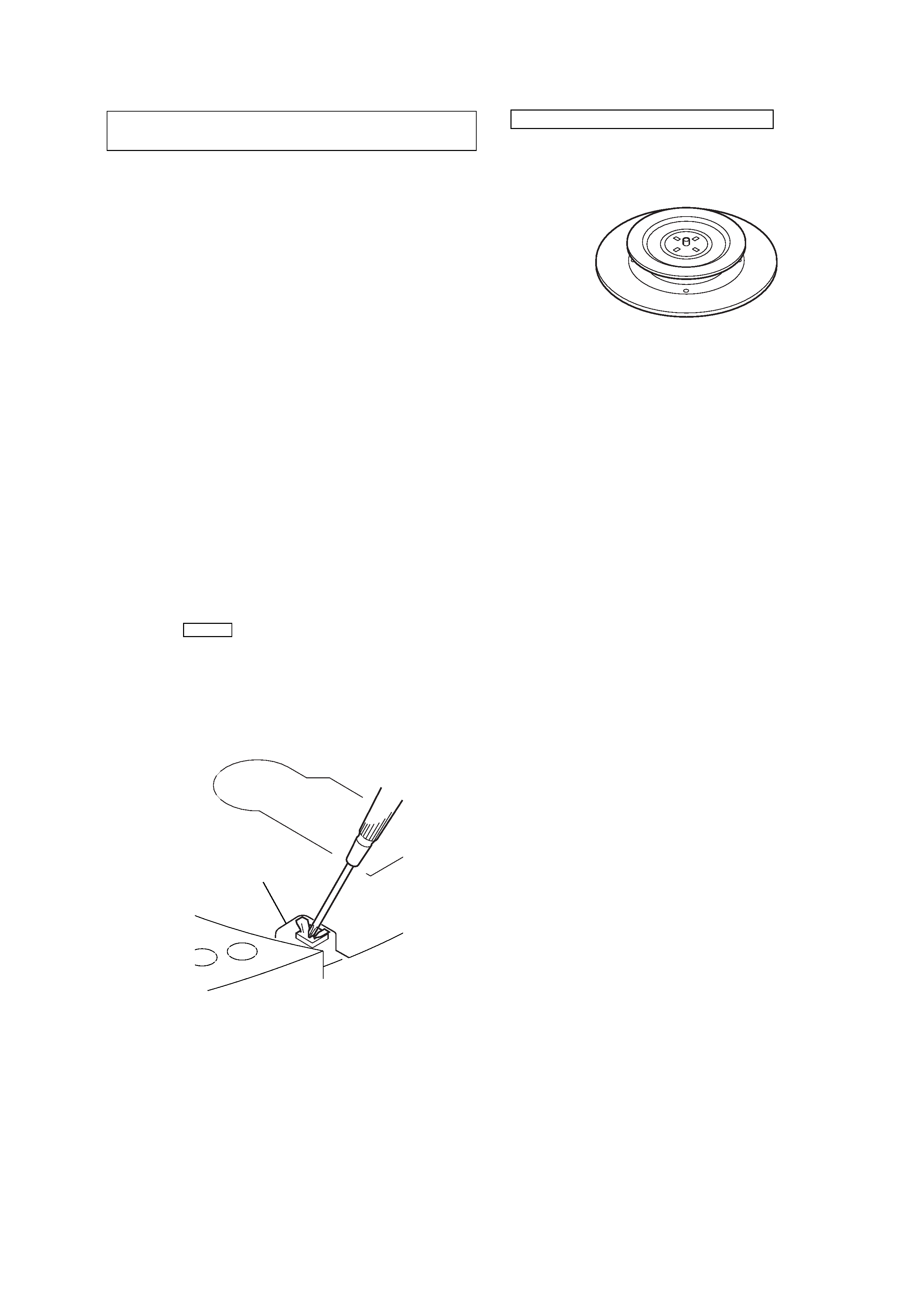
1. Open the upper lid.
2. Push the S301 as shown in Fig.1.
Note: Do not push the detection lever strongly, or it may be bent or dam-
aged.
3. Press the CD u button.
4. Check the object lens for confirming normal emission of the
laser diode. If not emitting, there is a trouble in the automatic
power control circuit or the optical pick-up.
In this operation, the object lens will move up and down 2
times along with inward motion for the focus search.
NOTES ON HANDLING THE OPTICAL PICK-UP
BLOCK OR BASE UNIT
CHUCK PLATE JIG ON REPAIRING
On repairing CD section, playing a disc without the CD lid, use
Chuck Plate Jig.
· Code number of Chuck Plate Jig: X-4918-255-1
Fig.1 Method to push the S301
4
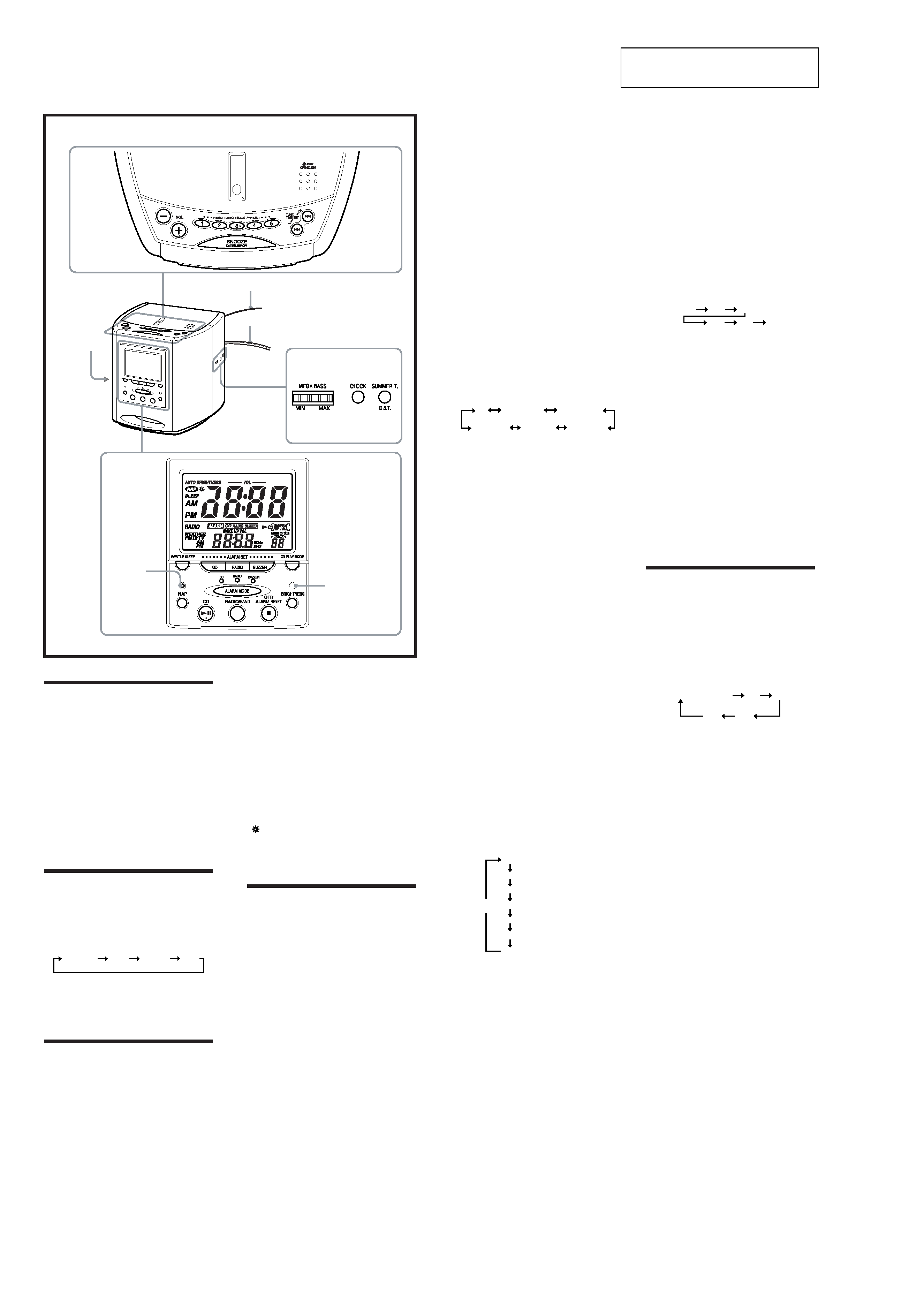
ICF-CD863V
Auto Brightness
sensor
NAP
indicator
FM wire antenna
AC power cord
i
(headphones)
jack
The VOL + and the PRESET TUNING 3 buttons have a
tactile dot.
The CD u button has a tactile dot.
Features
· TV/WEATHER/FM/AM 4 band PLL (phase
locked loop) synthesized clock radio
·Easy preset digital tuning with 25 memory
presets
· Built-in CD player with CD-R/RW playback
function
·High Quality 3D Sound with powerful MEGA
BASS sound system
·Triple Alarm (Radio, buzzer or CD) with the
extendable snooze function.
·Gentle Wake/Sleep Function
·Easy nap timer one push operating.
· LCD with backlight which has a auto
brightness control
·D.S.T. (Daylight Saving Time) Summer time
calculation.
Setting the Brightness
of the Backlight
Press BRIGHTNESS.
Each press changes the brightness of the backlight
as follows:
(high)
(middle)
(low)
(Auto
brightness)
The initial setting is Auto brightness.
When Auto brightness is selected, the Auto
brightness sensor detects ambient light and
automatically adjusts the backlight brightness of
the display in three levels.
Setting the Clock
and Date
1 Plug in the clock radio.
The display will flash "AM 12:00".
2 Press CLOCK for a few seconds.
You will hear a beep and the year will start to
flash in the display.
3 Press TUNE/TIME SET + or until the
correct year appears in the display.
4 Press CLOCK once.
5 Repeat steps 3 and 4 to set the month,
day, hour, and minute.
After setting the minute, press CLOCK to start
the counting of the seconds, and you will
hear two short beeps.
To display the year and date, press
SNOOZE·DATE/SLEEP OFF once for the date,
and within 4 seconds press it again for the year.
The display shows the date or year for a few
seconds and then changes back to the current
time.
To set the current time rapidly, hold down
TUNE/TIME SET + or .
In step 5, when you press CLOCK after the
minute setting to activate the clock, the seconds
start counting from zero.
To change the display to the
daylight saving time (summer time) indication
Press D.S.T./SUMMER T.
"
" is displayed and the time indication
changes to summer time.
To deactivate the summer time function, press
D.S.T./SUMMER T. again.
Setting the Alarm
This clock radio is equipped with 3 alarm
modes--CD, radio and buzzer. Before setting the
alarm, make sure to set the clock (see "Setting the
Clock and Date").
To Set the Alarm Time
To Set the CD Alarm:
For the CD alarm, the track you specified as the
Wake-up track is played first.
(If the CD play mode is set to "SHUFFLE" or
"SHUFFLE REP", however, all the tracks are
played in random order.)
1 Press ALARM SET CD for a few
seconds.
"ALARM", "CD" appear on the display.
After one beep, "ALARM" and the hour will
start to flash in the display.
2 Press TUNE/TIME SET + or until the
desired hour appears.
To set the hour rapidly, hold down TUNE/
TIME SET + or .
3 Press ALARM SET CD.
The minute will flash.
4 Repeat step 2 to set the minute and
press ALARM SET CD.
The wake-up track number flashes on the
display.
5 Press TUNE/TIME SET + or to select
the desired wake-up track number.
The wake-up track number can be set up to
99.
6 Press ALARM SET CD.
The wake-up volume level flashes on the
display.
7 Press TUNE/TIME SET + or to adjust
the wake-up volume level.
8 Press ALARM SET CD.
Two short beeps will confirm the setting.
To Set the Radio Alarm:
For the radio alarm, the station you specified as
the Wake-up station is played.
1 Press ALARM SET RADIO for a few
seconds.
"ALARM" and "RADIO" appear on the
display.
After one beep, "ALARM" and the hour will
start to flash on the display.
2 Press TUNE/TIME SET + or until the
desired hour appears.
To set the hour rapidly, hold down TUNE/
TIME SET + or .
3 Press ALARM SET RADIO.
The minute will flash.
4 Repeat step 2 to set the minute and
press ALARM SET RADIO.
"WAKE UP STA" appears and the preset
number flashes on the display.
5 Press TUNE/TIME SET + or to select
the wake-up station.
Preset number changes in the order as
follows:
P-
AM P1 to 5
FM1 P1 to 5
FM2 P1 to 5
TV P1 to 5
WEATHER
P1 to 5
"P" is the last received station.
You can directly select the desired wake-up
station by pressing RADIO/BAND or the
PRESET TUNING button while the indication
"P" is not displayed.
6 Press ALARM SET RADIO.
The wake-up volume level flashes on the
display.
7 Press TUNE/TIME SET + or to adjust
the wake-up volume level.
8 Press ALARM SET RADIO.
Two short beeps will confirm the setting.
To Set the Buzzer Alarm:
1 Press ALARM SET BUZZER for a few
seconds.
"ALARM" and "BUZZER" appear on the
display.
After one beep, "ALARM" and the hour will
start to flash on the display.
2 Press TUNE/TIME SET + or until the
desired hour appears.
To set the hour rapidly, hold down TUNE/
TIME SET + or .
3 Press ALARM SET BUZZER.
The minute will flash.
4 Repeat step 2 to set the minute and
press ALARM SET BUZZER.
Two short beeps will confirm the setting.
Note
The wake-up volume for the buzzer alarm is not
selectable by the setting.
To Set the Alarm Mode
Before setting the alarm mode, be sure to set the
alarm time. (See "To Set the Alarm Time".)
Repeat the pressing of ALARM MODE to select
the alarm mode you want. Every time you press
ALARM MODE, CD/RADIO/BUZZER indicator
changes in the order as follows:
CD
RADIO
BUZZER
CD+RADIO
CD+BUZZER
RADIO+BUZZER
CD+RADIO+BUZZER
OFF
The alarm time which plays or sounds next is
displayed.
To Check the Alarm Setting
For ALARM SET CD, pressing once displays the
alarm time, pressing twice displays the wake-up
track number, and pressing three times displays
the wake-up volume.
For ALARM SET RADIO, pressing once displays
the alarm time, pressing twice displays the wake-
up station, and pressing three times displays the
wake-up volume.
For ALARM SET BUZZER, pressing once displays
the alarm time.
The display shows the alarm setting for a few
seconds and then returns to the previous display.
Alarm time in CD alarm, radio alarm and buzzer
alarm is set at AM 12:00 when you purchased the
unit.
ALARM ON--
If you set the CD alarm and there is no disc in
the CD player, the buzzer alarm will sound in its
place at the time set.
For the buzzer alarm, the beeping of the alarm
becomes more rapid and sounds increasing in
volume (Gentle Wake function) after every few
seconds in three progressive stages.
When headphones (not supplied) are plugged
into the unit, buzzer alarm through the speakers
and the headphones regardless of the alarm
mode setting. In this case, the unit will not play a
CD or radio.
Note
When CD, radio and buzzer alarms are set for
the same time, the CD alarm takes precedence. If
the CD alarm is not set, the radio alarm takes
precedence.
To Doze for a Few More
Minutes
Press SNOOZE·DATE/SLEEP OFF.
The CD, radio or buzzer alarm turns off but will
be automatically activated again after about 10
minutes. Every time you press SNOOZE·DATE/
SLEEP OFF, the snooze time changes as follows:
10
20
50
60
30
40
The display shows the snooze time for a few
seconds and returns to show the current time.
When you press SNOOZE·DATE/SLEEP OFF
after the current time appeared, the snooze time
starts from 10 minutes again.
The maximum length of the snooze time is 60
minutes.
ALARM OFF--
The CD, radio, or buzzer alarm is turned off
automatically after 60 minutes.
To Stop the Alarm
Press OFF/ALARM RESET x to turn off the
alarm.
The alarm will come on again at the same time
the next day.
To Deactive the Alarm
Press ALARM MODE repeatedly until CD/
RADIO/BUZZER indicator go off.
Setting the Sleep
Timer
You can enjoy falling asleep to the CD or the
radio using the built-in sleep timer that turns off
the CD or the radio automatically after a preset
duration.
Press SLEEP during CD or radio play.
You can set the sleep timer to durations of 90,
60,30, or 15 minutes. Every push changes the
display as follows:
off (current time)
90
60
30
15
"SLEEP" will appear in the display when the
duration time is set.
The CD or the radio will play for the time you
set, then shut off.
When the sleep timer reaches a remaining time
of a few minutes, "SLEEP" will flash in the
display and the sound output will gradually
decrease in volume (Gentle Sleep function).
If you press VOL + or at this time, "SLEEP" will
light up and the decrease in the volume will
stop.
To turn off the CD or the radio before the preset
time, press SNOOZE·DATE/SLEEP OFF.
SECTION 2
GENERAL
This section is extracted from
instruction manual.
ICF-CD863V
5
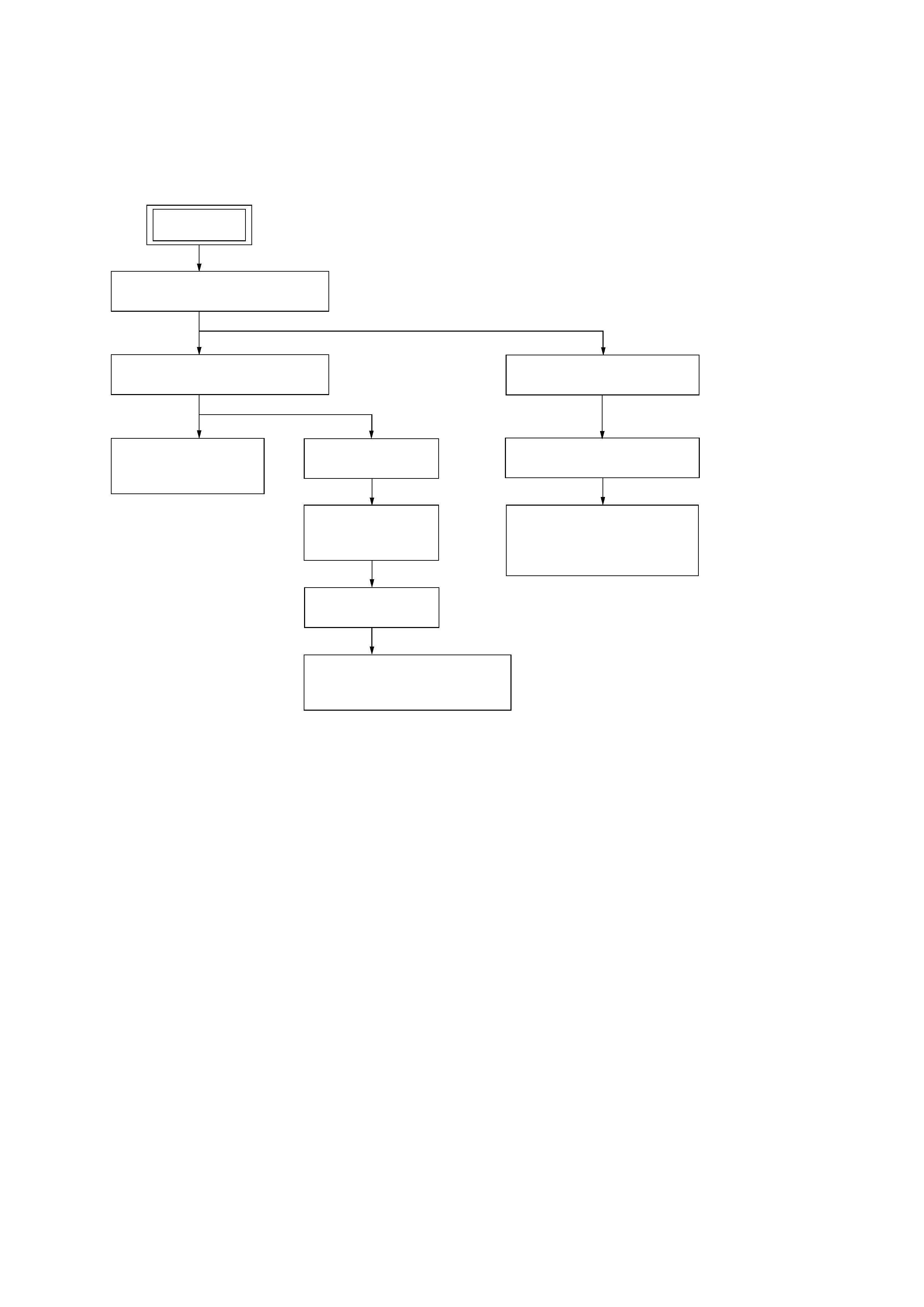
· This set can be disassembled in the order shown below.
3-1.
DISASSEMBLY FLOW
SECTION 3
DISASSEMBLY
3-2. CABINET (REAR) SECTION
(Page 6)
3-9. TRANSFORMER BOARD
(Page 9)
3-3. CABINET (UPPER) SECTION
(Page 6)
3-4. PANEL (SP) (,L),
PANEL (SP) (,R)
(Page 7)
3-6. KEY BOARD,
MAIN BOARD
(Page 8)
3-8. OPTICAL PICK-UP DEVICE
(KSS-213R)
(Page 9)
SET
3-5. CD LID ASSY
(Page 7)
3-10. BOX (SP) ASSY
(Page 10)
3-11. SPEAKER (8.2 cm)
(WOOFER) (SP301),
BOX (SP)
(Page 11)
3-7. CD BLOCK
(Page 8)