ICF-CD823
US Model
Canadian Model
AEP Model
Australian Model
SERVICE MANUAL
FM/AM CD CLOCK RADIO
SPECIFICATIONS
Model Name Using Similar Mechanism
NEW
Optical Device Name
KSM-213CDM
Optical Pick-UP Name
KSS-213C
CD player section
System: Compact disc digital audio system
Laser diode properties: Material: GaAlAs
Wavelength: 780 nm
Emission duration: Continuous
Laser output: Less than 44.6 µW
(This output is the value measured at a
distance of about 200 mm from the objective
lens surface on the optical pick-up block with
7 mm aperture.)
Frequency response: 20-20,000 Hz
+1
1.5 dB
Wow and flutter: Below measurable limit
Radio section
Frequency range:
Band
Channel step
US, Canadian:
FM
87.5-108 MHz
0.1 MHz
AM
530-1,710 kHz
10 kHz
AEP:
FM
87.5-108 MHz
0.05 MHz/0.1 MHz
AM
531-1,602 kHz
9 kHz
530-1,610 kHz
10 kHz
Australian:
FM
87.5-108 MHz
0.05 MHz
AM
531-1,602 kHz
9 kHz
General
Time display:
North and South America and Australia:
12-hour system
Other countries: 24-hour system
Speaker:
77 mm (3 1/8 inches) dia., 4
Output:
i
(headphones) jack (ø 3.5 mm stereo minijack)
(except North American model)
Power outputs:
1.2 W + 1.2 W
(at 10% harmonic distortion)
Power requirements:
North and South American model:
120 V AC, 60 Hz
Australian model:
240 V AC, 50 Hz
Other models:
220-230 V AC, 50 Hz
Dimensions:
Approx. 250
× 153 × 207 mm (w/h/d)
(Approx. 9 7/8
× 6 1/
8
× 8 1/
4 inches) incl.
projecting parts and controls
Mass:
Approx. 1,700 g (3 lb. 12 oz.)
Design and specifications are subject to change
without notice.
Ver 1.1 2001. 04
Sony Corporation
Personal Audio Company
Shinagawa Tec Service Manual Production Group
9-927-915-12
2001D1600-1
© 2001.4
-- 2 --
TABLE OF CONTENTS
1. GENERAL ········································································ 4
2. DISASSEMBLY
2-1. CABINET, LOWER ······················································ 5
2-2. MAIN BOARD ····························································· 6
2-3. PANEL (FRONT) SUB ASSY ······································ 6
2-4. OPTICAL PICK-UP BOLCK (KSM-213CDM) ·········· 7
2-5. TRANSFORMER BOARD ··········································· 7
3. TEST MODE ······························································· 8
4. ELECTRICAL ADJUSTMENTS ························ 10
5. DIAGRAMS
5-1. BLOCK DIAGRAM ··················································· 11
5-2. CIRCUIT BOARDS LOCATION ······························· 13
5-3. SCHEMATIC DIAGRAM
MAIN SECTION (1/2) ·········································· 14
5-4. SCHEMATIC DIAGRAM
MAIN SECTION (2/2) ·········································· 17
5-5. PRINTED WIRING BOARD
MAIN SECTION ·················································· 20
5-6. PRINTED WIRING BOARD
PANEL SECTION ················································· 23
5-7. IC PIN FUNCTION DESCRIPTION ························· 25
5-8. IC BLOCK DIAGRAMS ············································ 26
6. EXPLODED VIEWS
6-1. LOWER CABINET SECTION ··································· 29
6-2. UPPER CABINET SECTION ···································· 30
6-3. OPTICAL PICK-UP SECTION
(KSM-213CDM) ························································· 31
7. ELECTRICAL PARTS LIST ································· 32
ATTENTION AU COMPOSANT AYANT RAPPORT
À LA SÉCURITÉ!
LES COMPOSANTS IDENTIFIÉS PAR UNE MARQUE
!
SUR LES DIAGRAMMES SCHÉMATIQUES ET LA LISTE
DES PIÈCES SONT CRITIQUES POUR LA SÉCURITÉ
DE FONCTIONNEMENT. NE REMPLACER CES COM-
POSANTS QUE PAR DES PIÈCES SONY DONT LES
NUMÉROS SONT DONNÉS DANS CE MANUEL OU DANS
LES SUPPLÉMENTS PUBLIÉS PAR SONY.
SAFETY-RELATED COMPONENT WARNING!!
COMPONENTS IDENTIFIED BY MARK
! OR DOTTED
LINE WITH MARK
! ON THE SCHEMATIC DIAGRAMS
AND IN THE PARTS LIST ARE CRITICAL TO SAFE
OPERATION. REPLACE THESE COMPONENTS WITH
SONY PARTS WHOSE PART NUMBERS APPEAR AS
SHOWN IN THIS MANUAL OR IN SUPPLEMENTS
PUBLISHED BY SONY.
SAFETY CHECK-OUT
After correcting the original service problem, perform the following
safety check before releasing the set to the customer:
Check the antenna terminals, metal trim, "metallized" knobs, screws,
and all other exposed metal parts for AC leakage.
Check leakage as described below.
LEAKAGE TEST
The AC leakage from any exposed metal part to earth ground and
from all exposed metal parts to any exposed metal part having a
return to chassis, must not exceed 0.5 mA (500 microampers.).
Leakage current can be measured by any one of three methods.
1. A commercial leakage tester, such as the Simpson 229 or RCA
WT-540A. Follow the manufacturers' instructions to use these
instruments.
2. A battery-operated AC milliammeter. The Data Precision 245
digital multimeter is suitable for this job.
3. Measuring the voltage drop across a resistor by means of a VOM
or battery-operated AC voltmeter. The "limit" indication is 0.75
V, so analog meters must have an accurate low-voltage scale.
The Simpson 250 and Sanwa SH-63Trd are examples of a
passive VOM that is suitable. Nearly all battery operated digital
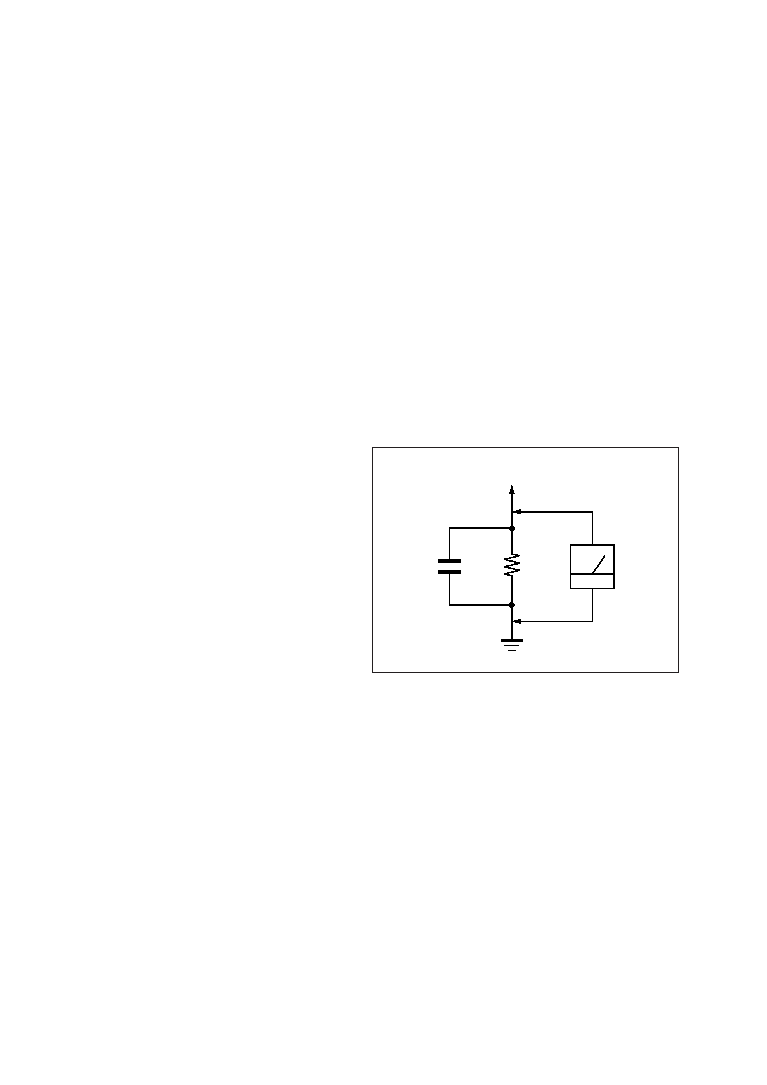
multimeters that have a 2 V AC range are suitable. (See Fig. A)
Fig. A.
Using an AC voltmeter to check AC leakage.
Note on chip component replacement
· Never reuse a disconnected chip component.
· Notice that the minus side of a tantalum capacitor may be dam-
aged by heat.
1.5 k
0.15
µF
AC
voltmeter
(0.75 V)
To Exposed Metal
Parts on Set
Earth Ground
-- 3 --
The laser diode in the optical pick-up block may suffer electrostatic
break-down because of the potential difference generated by the
charged electrostatic load, etc. on clothing and the human body.
During repair, pay attention to electrostatic break-down and also
use the procedure in the printed matter which is included in the
repair parts.
The flexible board is easily damaged and should be handled with
care.
NOTES ON LASER DIODE EMISSION CHECK
The laser beam on this model is concentrated so as to be focused on
the disc reflective surface by the objective lens in the optical pick-
up block. Therefore, when checking the laser diode emission,
observe from more than 30 cm away from the objective lens.
NOTES ON HANDLING THE OPTICAL PICK-UP
BLOCK OR BASE UNIT
CAUTION
Use of controls or adjustments or performance of procedures
other than those specified herein may result in hazardous
radiation exposure.
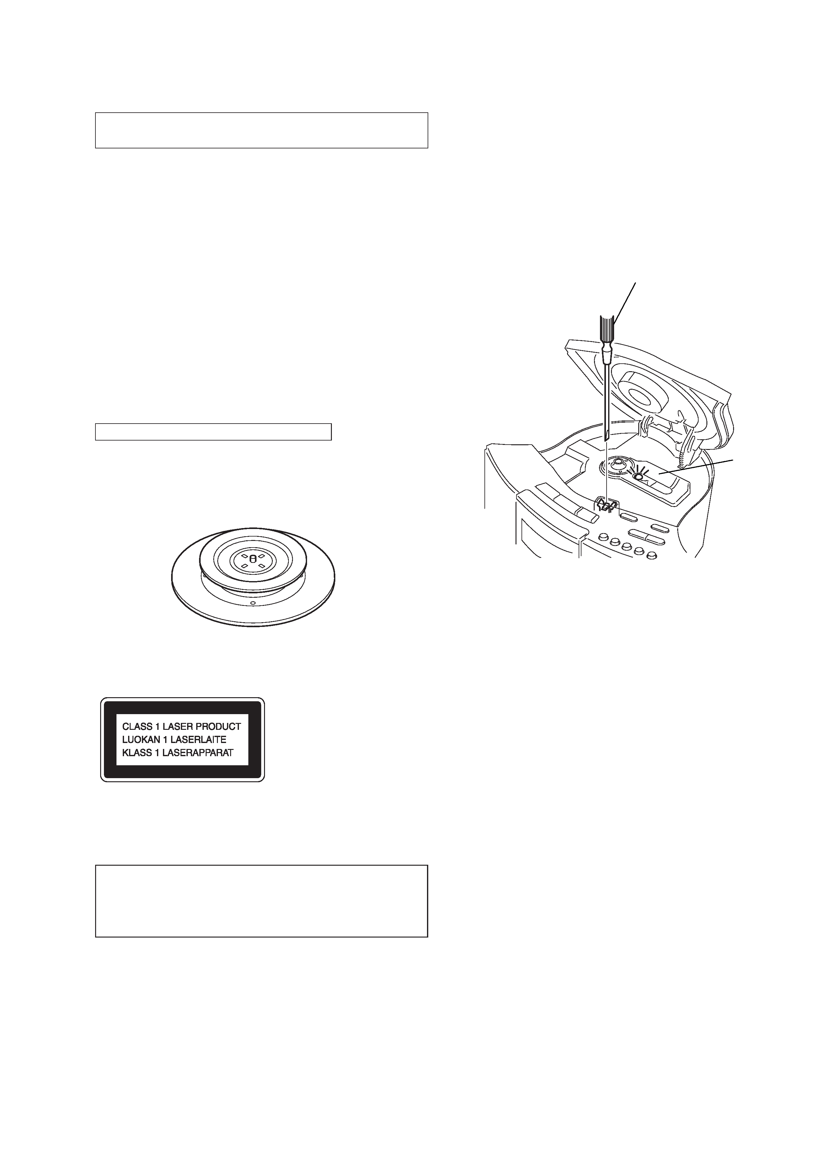
This Compact Disc player is classified as a CLASS 1
LASER product.
The CLASS 1 LASER PRODUCT label is located on the
bottom exterior.
CHUCK PLATE JIG ON REPAIRING
On repairing CD section, playing a disc without the CD lid, use
Chuck Plate Jig.
· Code number of Chuck Plate Jig: X-4918-255-1
LASER DIODE AND FOCUS SEARCH
OPERATION CHECK
1. Open the CD lid.
2. Turn on S501 as following figure.
3. Confirm that the laser diode emission while observing the
objecting lens. When there is no emission, Auto Power Control
circuit or Optical Pick-up is broken.
Objective lens moves up and down once for the focus search.
Insert a precision
screwdriver and
push S501.
laser diode
emission
-- 4 --
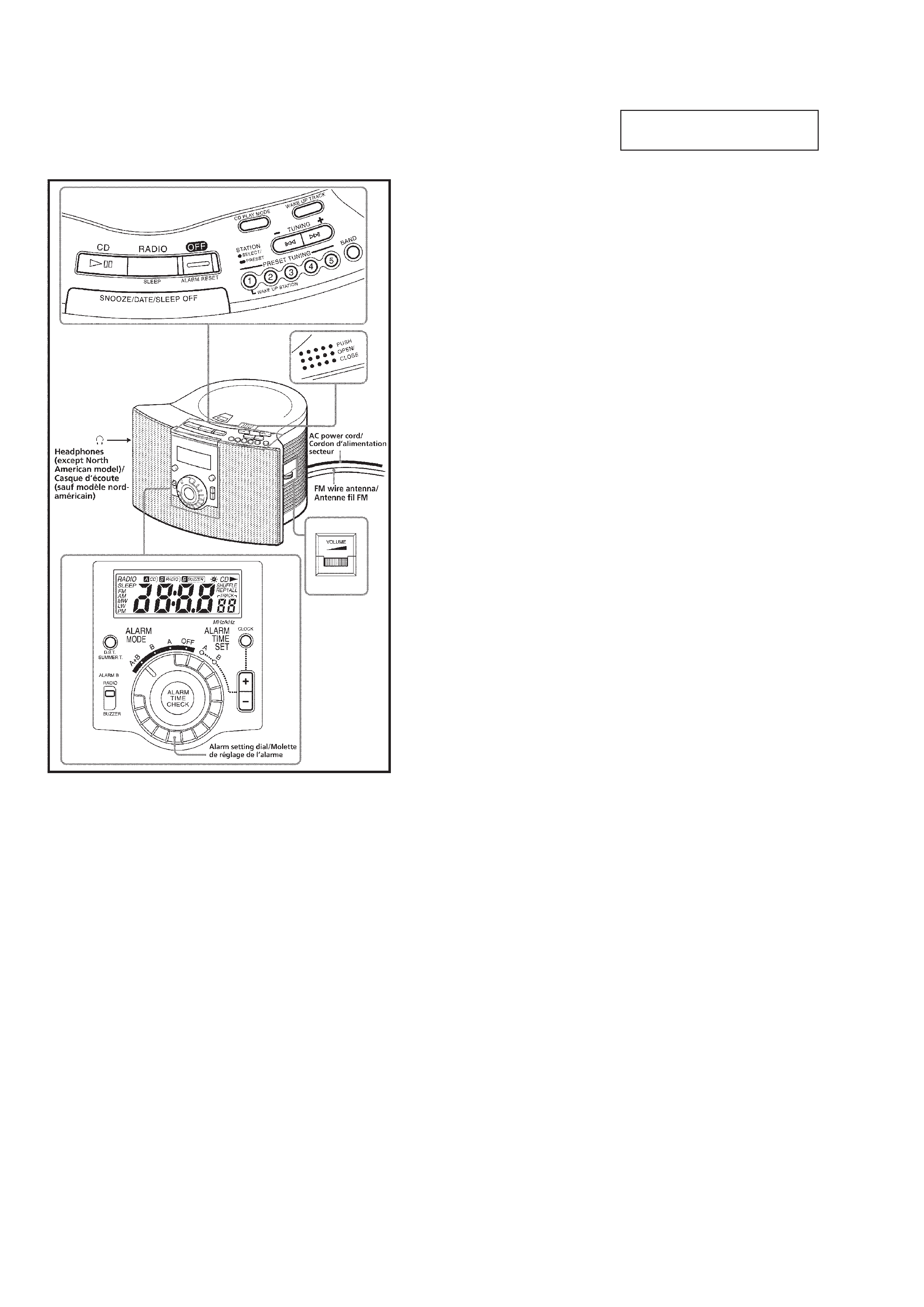
SECTION 1
GENERAL
Setting the Clock
and Date
1 Set the alarm setting dial to ALARM
MODE OFF.
2 Plug in the clock radio.
The display will flash "AM 12:00" or "0:00".
3 Press CLOCK for a few seconds.
You will hear a beep and the year will start to
flash in the display.
4 Press CLOCK + or until the correct
year appears in the display.
5 Press CLOCK once.
6 Repeat steps 4 and 5 to set the month,
day, hour, and minute.
After setting the minute, press CLOCK to start
the counting of the seconds, and you will
hear two short beeps.
· To display the year and date, press SNOOZE/
DATE/SLEEP OFF once for the date, and within
2 seconds press it again for the year. The
display shows the date or year for a few
seconds and then changes back to the current
time.
· To set the current time rapidly, hold down
CLOCK + or .
· The clock system varies depending on the
model you own.
12-hour system: "AM 12:00" = midnight
24-hour system: "0:00" = midnight
· In step 6, when you press CLOCK after the
minute setting to activate the clock, the seconds
start counting from zero.
· When the alarm setting dial is set to ALARM
TIME SET A or B, the clock cannot be set.
To change the display to the
daylight saving time (summer time)
indication
Press D.S.T./SUMMER T.
"s" is displayed and the time indication
changes to summer time.
To deactivate the summer time function, press
D.S.T./SUMMER T. again.
This section is extracted from
instruction manual.
-- 5 --
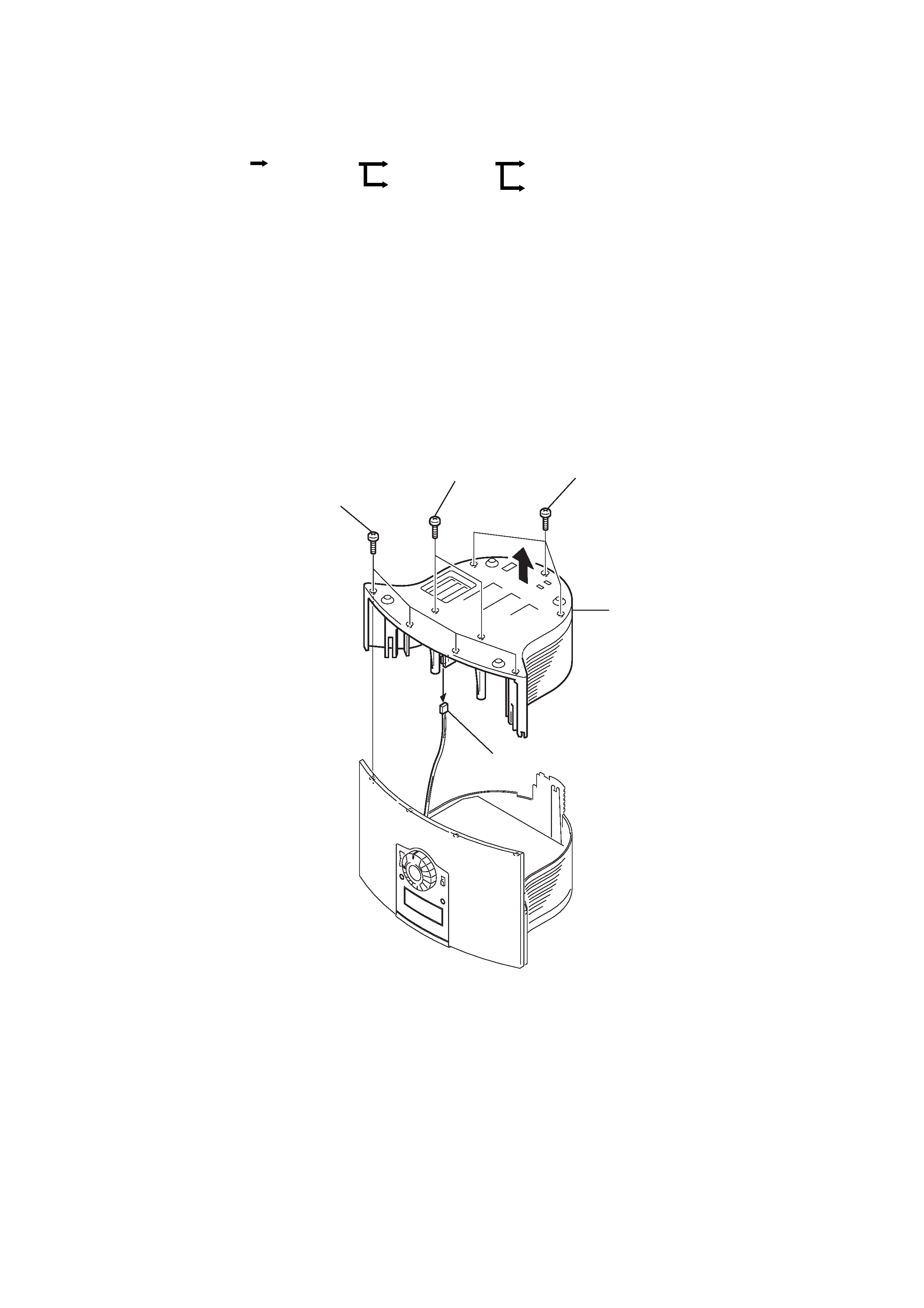
2-1. CABINET, LOWER
Note: Follow the disassembly procedure in the numerical order given.
SECTION 2
DISASSEMBLY
Optical pick-up block (KSM-213CDM)
Transformer board
Main board
Cabinet, lower
Set
Panel (front) sub assy
2 Two screws
(+P 3
× 14)
3 Three screws
(+P 3
× 14)
5 Cabinet, lower
4 Connector
1 Four screws
(+BVTP 3
× 10)
· The equipment can be removed using the following procedure.