MICROFILM
SERVICE MANUAL
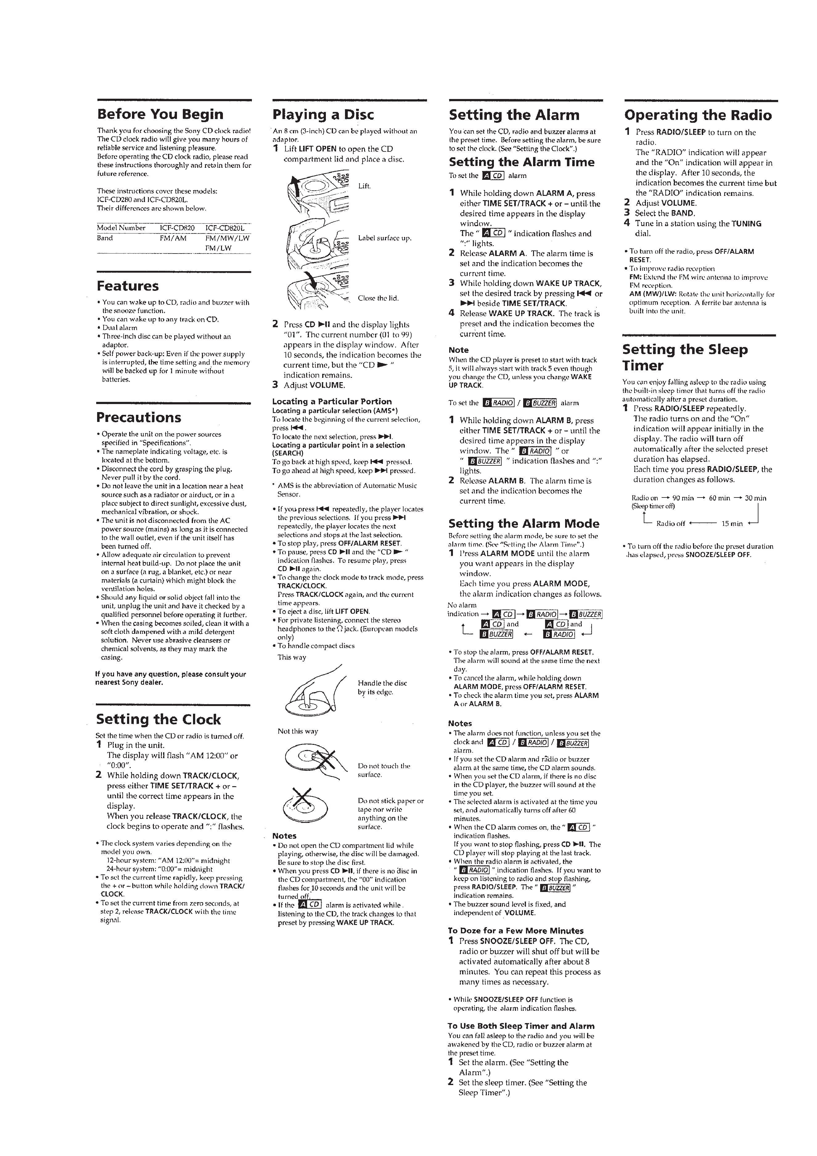
CD CLOCK RADIO
US Model
Canadian Model
E Model
Australian Model
ICF-CD820
AEP Model
ICF-CD820/CD820L
UK Model
ICF-CD820L
Model Name Using Similar Mechanism
CFD-550
Optical Device Name
KSM-213BAN
Optical Pick-UP Name
KSS-213B
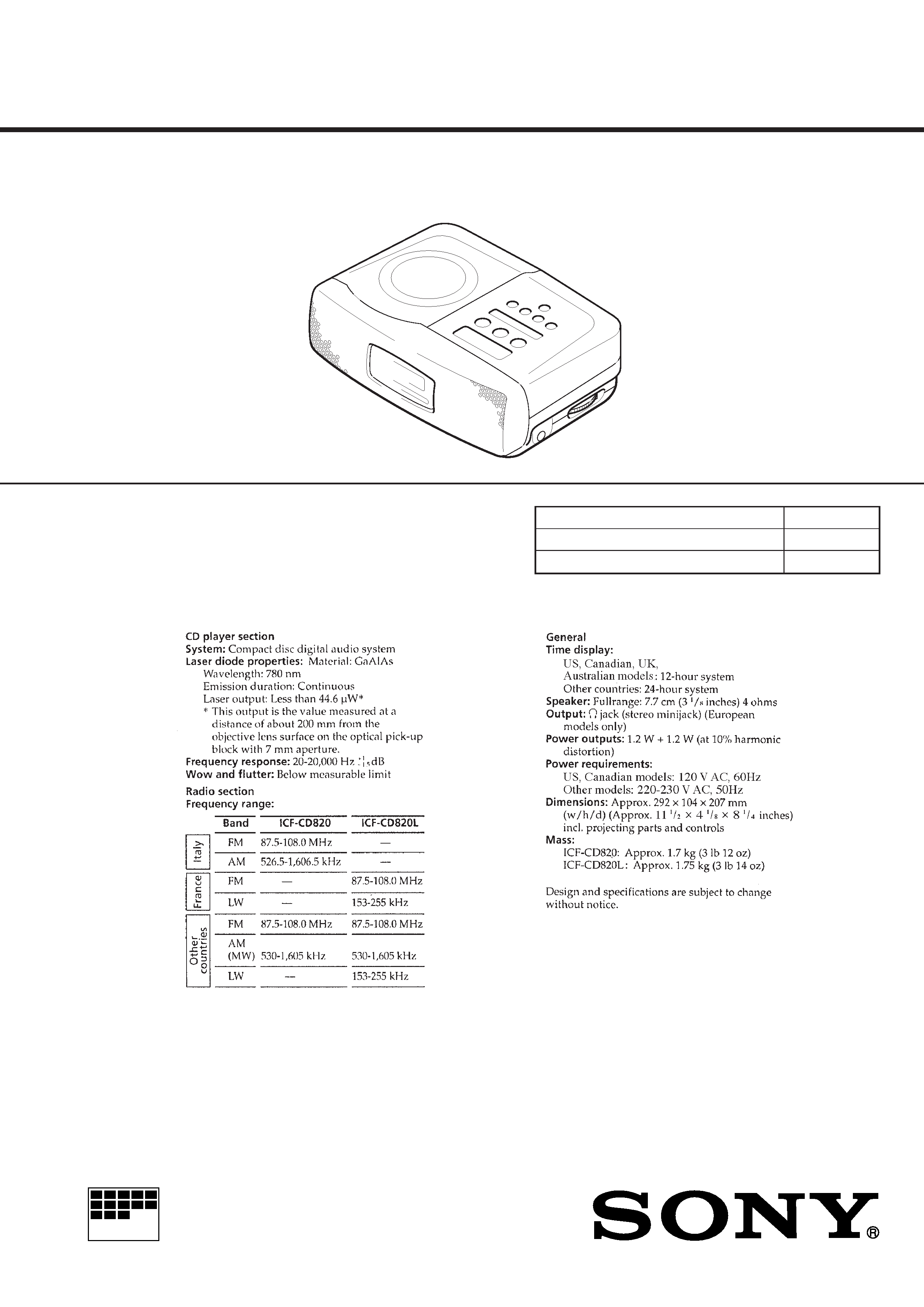
SPECIFICATIONS
ICF-CD820/CD820L
2
TABLE OF CONTENTS
1.
SERVICING NOTES ............................................... 2
2.
GENERAL ................................................................. 4
3.
DISASSEMBLY ......................................................... 6
4.
ELECTRICAL ADJUSTMENTS
Tuner Section ..................................................................
9
CD Section ...................................................................... 11
5.
DIAGRAMS
5-1. Printed Wiring Boards .................................................... 15
5-2. Schematic Diagram ......................................................... 19
5-3. IC Pin Function Description ........................................... 29
6.
EXPLODED VIEWS ................................................ 31
7.
ELECTRICAL PARTS LIST ............................... 34
ATTENTION AU COMPOSANT AYANT RAPPORT
À LA SÉCURITÉ!
LES COMPOSANTS IDENTIFIÉS PAR UNE MARQUE
!
SUR LES DIAGRAMMES SCHÉMATIQUES ET LA LISTE
DES PIÈCES SONT CRITIQUES POUR LA SÉCURITÉ
DE FONCTIONNEMENT. NE REMPLACER CES COM-
POSANTS QUE PAR DES PIÈCES SONY DONT LES
NUMÉROS SONT DONNÉS DANS CE MANUEL OU
DANS LES SUPPLÉMENTS PUBLIÉS PAR SONY.
SAFETY-RELATED COMPONENT WARNING!!
COMPONENTS IDENTIFIED BY MARK
! OR DOTTED
LINE WITH MARK
! ON THE SCHEMATIC DIAGRAMS
AND IN THE PARTS LIST ARE CRITICAL TO SAFE
OPERATION. REPLACE THESE COMPONENTS WITH
SONY PARTS WHOSE PART NUMBERS APPEAR AS
SHOWN IN THIS MANUAL OR IN SUPPLEMENTS PUB-
LISHED BY SONY.
SECTION 1
SERVICING NOTES
MODEL IDENTIFICATION
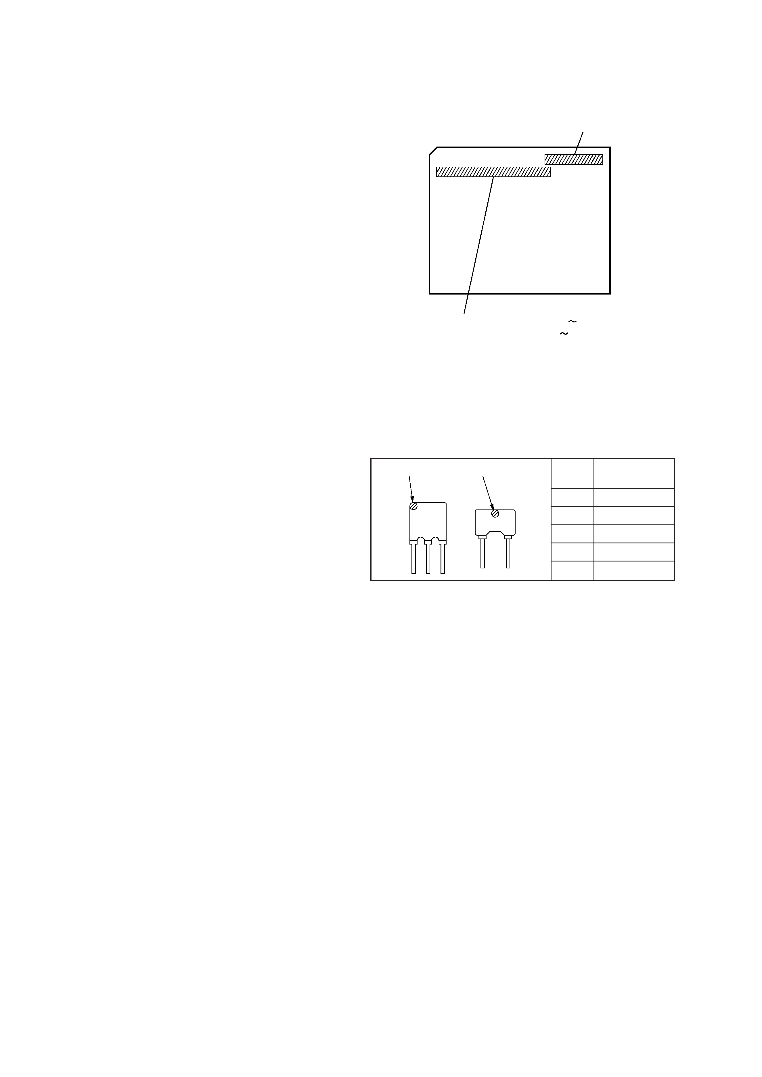
· HOW TO CHANGED THE CERAMIC FILTERS
This model is used two ceramic filters of CF2, CF3.
You must use same type of color marked ceramic filters in order
to meet same specifications.
Therefore, the ceramic filter must change two pieces together since
it's supply two pieces in one package as a spare parts.
mark
center
frequency
red
10.70 MHz
blue
10.67 MHz
orange
10.73 MHz
black
10.64 MHz
white
10.76 MHz
mark
CF2
CF3
mark
S® MODEL NO.
MADE IN MALAYSIA
ICF-CD820/CD820L
US, Canadian models: AC: 120 V
60 Hz 15 W
Other models: AC: 220 230 V
50 Hz 15 W
3
SAFETY CHECK-OUT
After correcting the original service problem, perform the follow-
ing safety check before releasing the set to the customer:
Check the antenna terminals, metal trim, "metallized" knobs,
screws, and all other exposed metal parts for AC leakage.
Check leakage as described below.
LEAKAGE TEST
The AC leakage from any exposed metal part to earth ground and
from all exposed metal parts to any exposed metal part having a
return to chassis, must not exceed 0.5 mA (500 microampers.).
Leakage current can be measured by any one of three methods.
1. A commercial leakage tester, such as the Simpson 229 or RCA
WT-540A. Follow the manufacturers' instructions to use these
instruments.
2. A battery-operated AC milliammeter. The Data Precision 245
digital multimeter is suitable for this job.
3. Measuring the voltage drop across a resistor by means of a
VOM or battery-operated AC voltmeter. The "limit" indica-
tion is 0.75 V, so analog meters must have an accurate low-
voltage scale. The Simpson 250 and Sanwa SH-63Trd are ex-
amples of a passive VOM that is suitable. Nearly all battery
operated digital multimeters that have a 2 V AC range are suit-
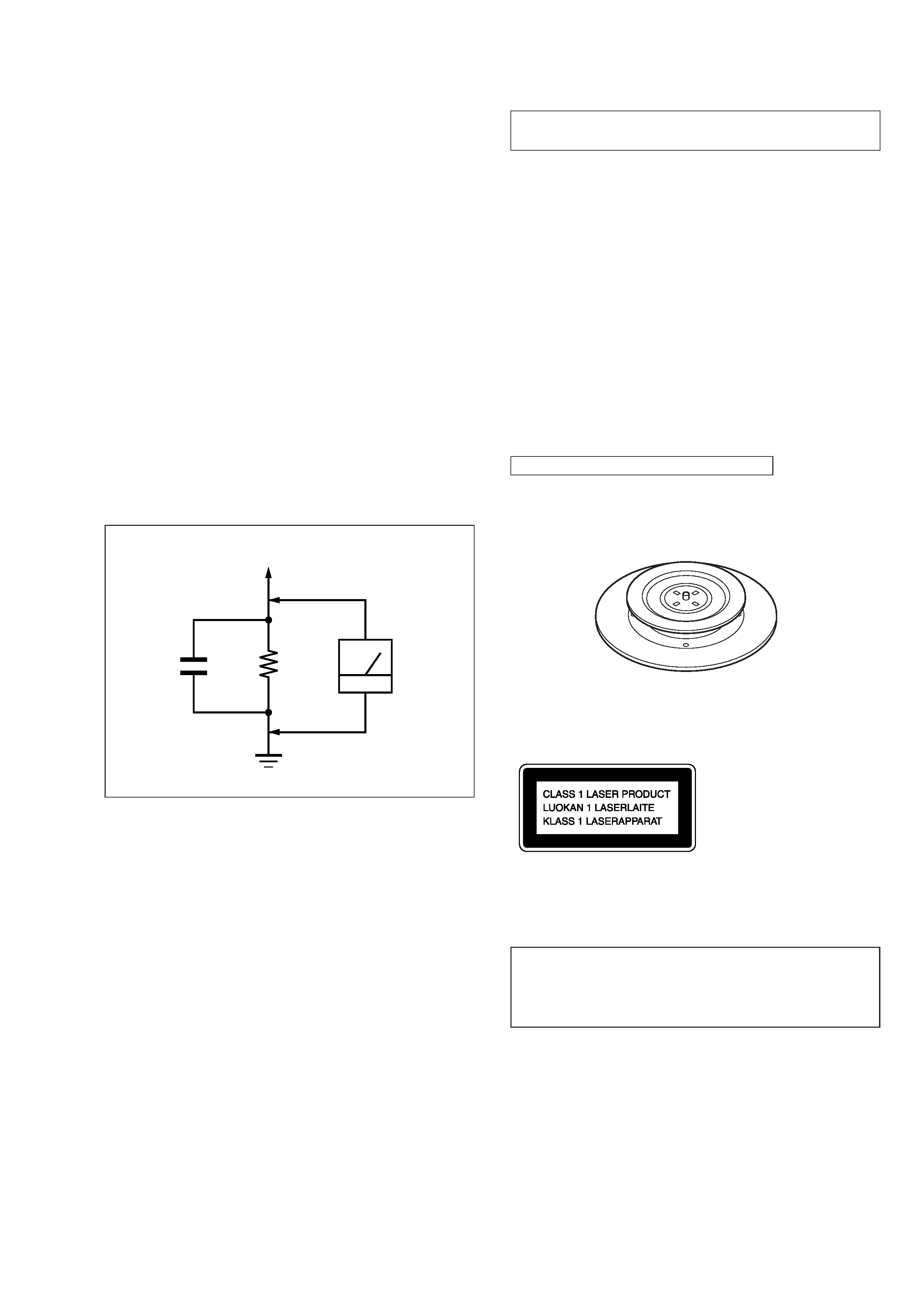
able. (See Fig. A)
Fig. A.
Using an AC voltmeter to check AC leakage.
1.5 k
0.15
µF
AC
voltmeter
(0.75 V)
To Exposed Metal
Parts on Set
Earth Ground
The laser diode in the optical pick-up block may suffer electro-
static break-down because of the potential difference generated
by the charged electrostatic load, etc. on clothing and the human
body.
During repair, pay attention to electrostatic break-down and also
use the procedure in the printed matter which is included in the
repair parts.
The flexible board is easily damaged and should be handled with
care.
NOTES ON LASER DIODE EMISSION CHECK
The laser beam on this model is concentrated so as to be focused
on the disc reflective surface by the objective lens in the optical
pick-up block. Therefore, when checking the laser diode emis-
sion, observe from more than 30 cm away from the objective lens.
NOTES ON HANDLING THE OPTICAL PICK-UP
BLOCK OR BASE UNIT
CAUTION
Use of controls or adjustments or performance of procedures
other than those specified herein may result in hazardous ra-
diation exposure.
This Compact Disc player is classified as a CLASS 1
LASER product.
The CLASS 1 LASER PRODUCT label is located on the
bottom exterior.
Note on chip component replacement
· Never reuse a disconnected chip component.
· Notice that the minus side of a tantalum capacitor may be dam-
aged by heat.
CHUCK PLATE JIG ON REPAIRING
On repairing CD section, playing a disc without the CD lid, use
Chuck Plate Jig.
· Code number of Chuck Plate Jig: X-4918-255-1
4
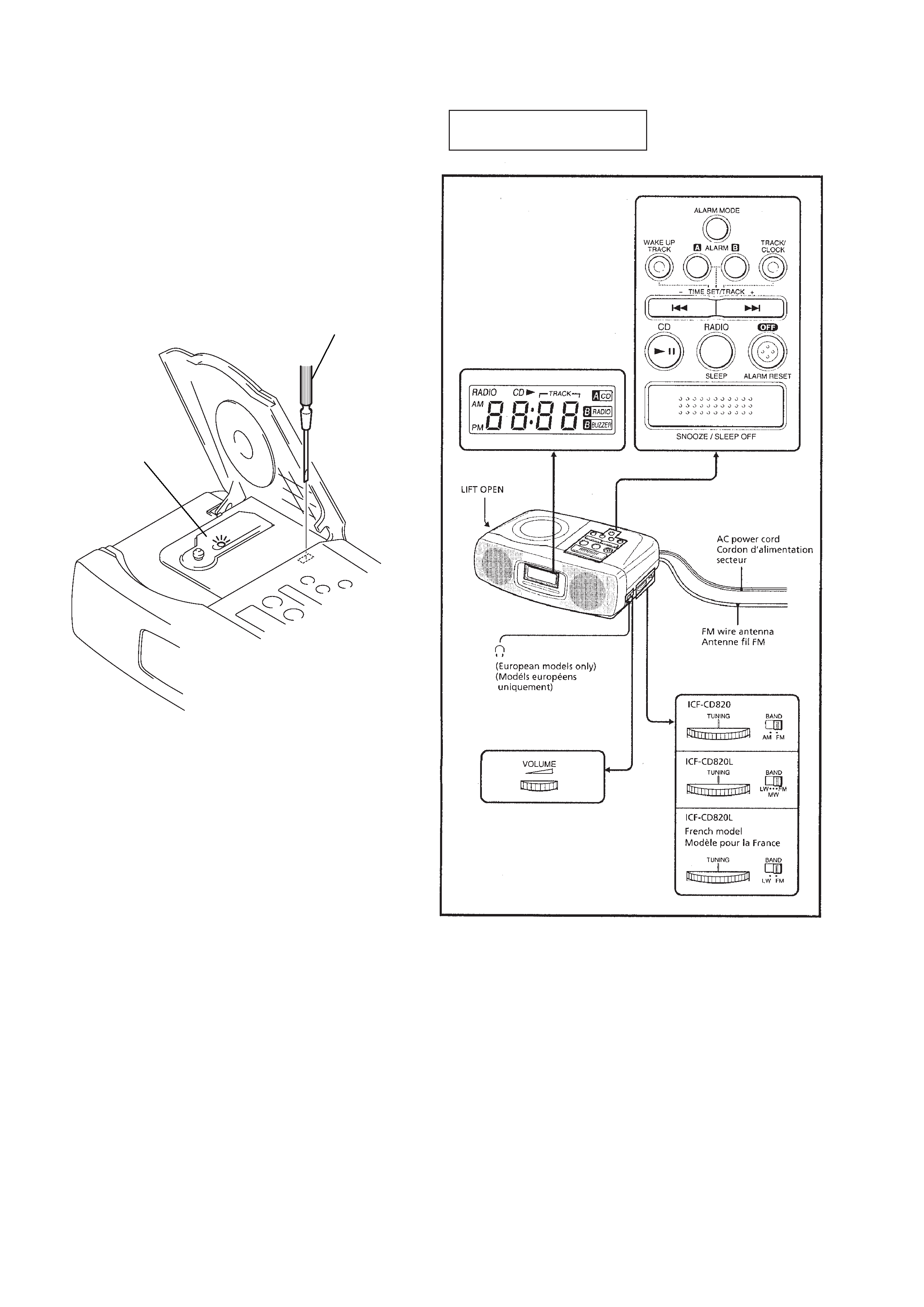
LASER DIODE AND FOCUS SEARCH
OPERATION CHECK
1. Open the CD lid.
2. Turn on S420 as following figure.
3. Confirm that the laser diode emission while observing the ob-
jecting lens. When there is no emission, Auto Power Control
circuit or Optical Pick-up is broken.
Objective lens moves up and down once for the focus search.
SECTION 2
GENERAL
This section is extracted from
instruction manual.
Insert a precision
screwdriver and
push S420.
laser diode
emission
5