SERVICE MANUAL
FM/AM CD KITCHEN CLOCK RADIO
US Model
Canadian Model
AEP Model
SPECIFICATIONS
ICF-CD513
Model Name Using Similar Mechanism
ICF-CD533
CD Mechanism Type
KSL-213BGN (FORMER)
FLM-CD513-149 (NEW)
Optical Pick-up Block Name
KSM-213BGN (FORMER)
KSM-213RCP (NEW)
Optical Pick-UP Name
KSS-213B (FORMER)
KSS-213R (NEW)
CD player section
System:
Compact disc digital audio system
Laserdiode properties:
Material: GaAlAs
Wavelength: 780 nm
Emission duration: Continuous
Laser output: Less than 44.6 µW
(This output is the value measured at a
distance of about 200 mm from the objective
lens surface on the optical pick-up block with
7 mm aperture.)
Frequency response:
20-20 000 Hz +1 dB
1.5
Wow and flutter:
Below measurable limit
Radio section
Frequencyrange:
US, Canadian models
Band
Frequency range
Channel step
FM
87.5-108 MHz
0.1 MHz
AM
530-1 710 kHz
10 kHz
AEP model
Band
Frequency range
Channel step
FM
87.5-108 MHz
0.05 MHz
AM
531-1 602 kHz
9 kHz
FM
87.5-108 MHz
0.1 MHz
AM
530-1 610 kHz
10 kHz
General
Time display:
US, Canadian models: 12-hour system
AEP model: 24-hour system
Speaker:
66 mm (2 5/8 inches) dia., 4
Power outputs:
1.2 W + 1.2 W
(at 10% harmonic distortion)
Power requirements:
US, Canadian models: 120 V AC, 60 Hz
AEP model: 220-230 V AC, 50 Hz
Dimensions:
Approx. 365 × 106 × 281 mm (w/h/d)
(Approx. 14 3/8 × 4 1/4 × 11 1/8 inches) incl.
projecting parts and controls
Mass:
Approx. 2.9 kg (6 lb. 6 oz.)
Supplied accessories:
Mounting screws (4), Template (1),
Spacers (4), Cord clamp (1)
Design and specifications are subject to change
without notice.
Ver 1.1 2003. 08
9-927-968-12
Sony Corporation
2003H05-1
Personal Audio Company
C
2003.08
Published by Sony Engineering Corporation
2
TABLE OF CONTENTS
1.
SERVICING NOTES ............................................... 3
2.
GENERAL ................................................................... 4
3.
DISASSEMBLY ......................................................... 6
4.
TEST MODE .............................................................. 9
5.
ELECTRICAL ADJUSTMENTS
Tuner Section .................................................................. 11
CD Section ...................................................................... 12
6.
DIAGRAMS
6-1. Block Diagram CD Section ..................................... 15
6-2. Block Diagram TUNER Section ............................. 17
6-3. Block Diagram MAIN Section ................................ 19
6-4. Printed Wiring Boards ..................................................... 23
6-5. Schematic Diagram
MAIN (1/4)/KEY/LED Boards ................................ 27
6-6. Schematic Diagram MAIN Board (2/4) .................. 29
6-7. Schematic Diagram
MAIN (3/4)/LOADING/MOTOR Boards ................ 31
6-8. Schematic Diagram
MAIN (4/4)/VOLUME/POWER Boards ................. 33
6-9. IC Pin Function Description ........................................... 40
7.
EXPLODED VIEWS ................................................ 42
8.
ELECTRICAL PARTS LIST ............................... 46
ATTENTION AU COMPOSANT AYANT RAPPORT
À LA SÉCURITÉ!
LES COMPOSANTS IDENTIFIÉS PAR UNE MARQUE 0
SUR LES DIAGRAMMES SCHÉMATIQUES ET LA LISTE
DES PIÈCES SONT CRITIQUES POUR LA SÉCURITÉ
DE FONCTIONNEMENT. NE REMPLACER CES COM-
POSANTS QUE PAR DES PIÈCES SONY DONT LES
NUMÉROS SONT DONNÉS DANS CE MANUEL OU
DANS LES SUPPLÉMENTS PUBLIÉS PAR SONY.
SAFETY-RELATED COMPONENT WARNING!!
COMPONENTS IDENTIFIED BY MARK 0 OR DOTTED
LINE WITH MARK 0 ON THE SCHEMATIC DIAGRAMS
AND IN THE PARTS LIST ARE CRITICAL TO SAFE
OPERATION. REPLACE THESE COMPONENTS WITH
SONY PARTS WHOSE PART NUMBERS APPEAR AS
SHOWN IN THIS MANUAL OR IN SUPPLEMENTS PUB-
LISHED BY SONY.
CAUTION
Use of controls or adjustments or performance of procedures
other than those specified herein may result in hazardous ra-
diation exposure.
SAFETY CHECK-OUT
After correcting the original service problem, perform the follow-
ing safety check before releasing the set to the customer:
Check the antenna terminals, metal trim, "metallized" knobs,
screws, and all other exposed metal parts for AC leakage.
Check leakage as described below.
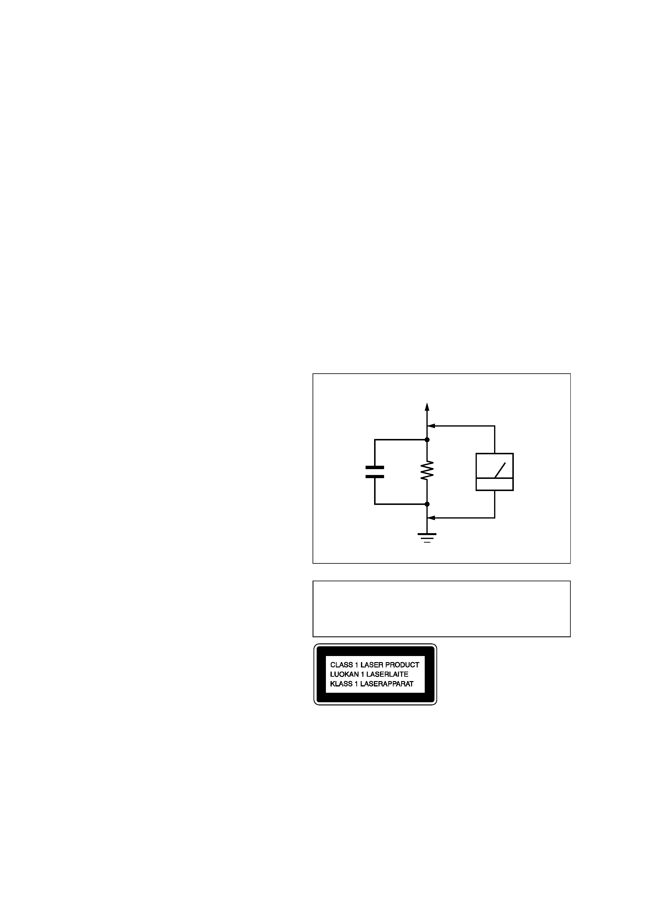
LEAKAGE TEST
The AC leakage from any exposed metal part to earth ground and
from all exposed metal parts to any exposed metal part having a
return to chassis, must not exceed 0.5 mA (500 microampers.).
Leakage current can be measured by any one of three methods.
1. A commercial leakage tester, such as the Simpson 229 or RCA
WT-540A. Follow the manufacturers' instructions to use these
instruments.
2. A battery-operated AC milliammeter. The Data Precision 245
digital multimeter is suitable for this job.
3. Measuring the voltage drop across a resistor by means of a
VOM or battery-operated AC voltmeter. The "limit" indica-
tion is 0.75 V, so analog meters must have an accurate low-
voltage scale. The Simpson 250 and Sanwa SH-63Trd are ex-
amples of a passive VOM that is suitable. Nearly all battery
operated digital multimeters that have a 2 V AC range are suit-
able. (See Fig. A)
Fig. A.
Using an AC voltmeter to check AC leakage.
1.5 k
0.15
µF
AC
voltmeter
(0.75 V)
To Exposed Metal
Parts on Set
Earth Ground
Notes on chip component replacement
· Never reuse a disconnected chip component.
· Notice that the minus side of a tantalum capacitor may be dam-
aged by heat.
Flexible Circuit Board Repairing
· Keep the temperature of the soldering iron around 270 °C dur-
ing repairing.
· Do not touch the soldering iron on the same conductor of the
circuit board (within 3 times).
· Be careful not to apply force on the conductor when soldering
or unsoldering.
This Compact Disc player is classified
as a CLASS 1 LASER product.
The CLASS 1 LASER PRODUCT label
is located on the top exterior.
3
SECTION 1
SERVICING NOTES
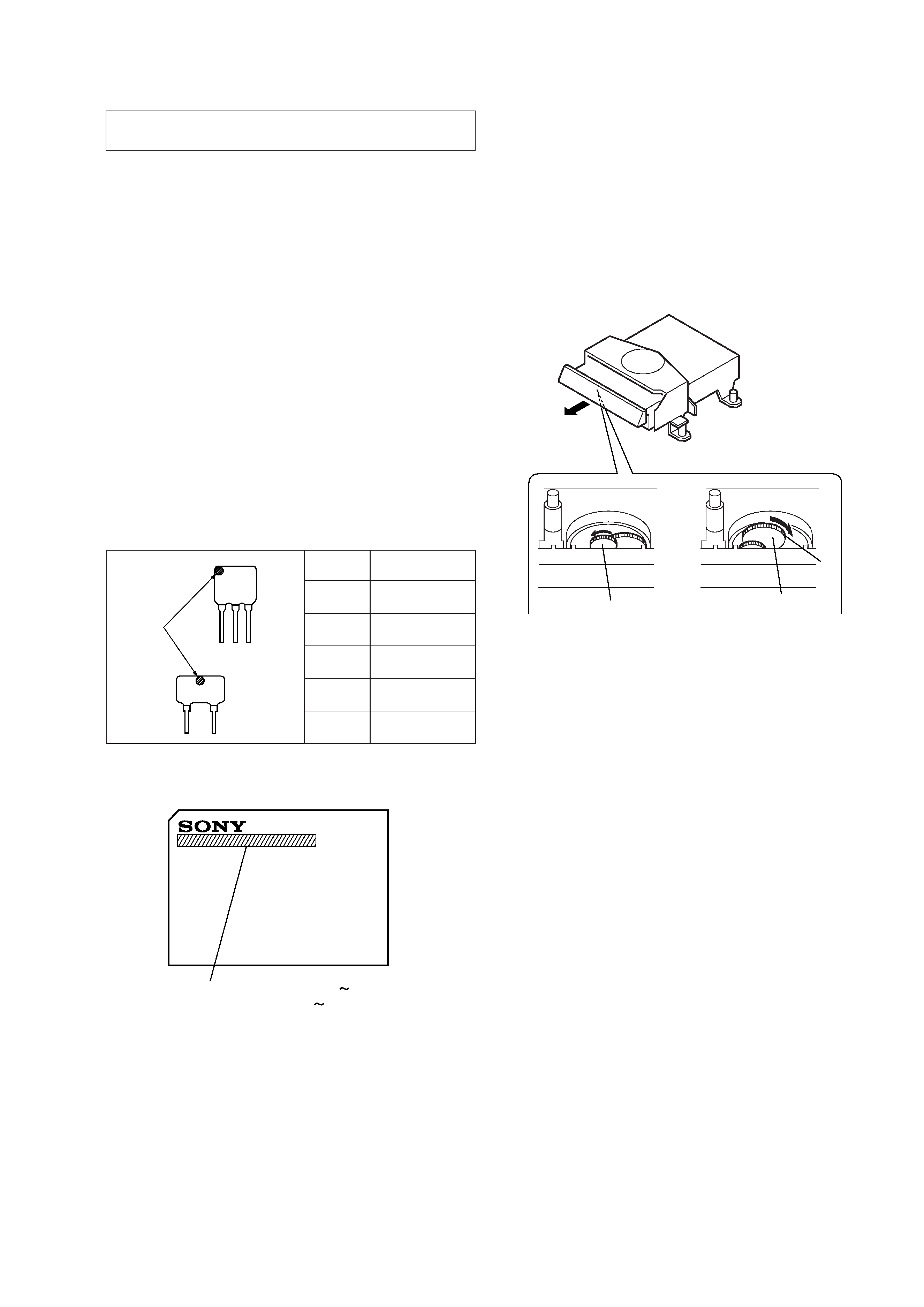
CF3
CF1
mark
Mark
Center frequency
red
10.70 MHz
blue
10.67 MHz
orange
10.73 MHz
black
10.64 MHz
white
10.76 MHz
HOW TO CHANGED THE CERAMIC FILTERS
This model is used two ceramic filters of CF1 and CF3.
You must used same type of color marked ceramic filters in order
to meet same specifications.
Therefore, the ceramic filter must changed two pieces together
since it's supply two pieces in one package as a spare parts.
MODEL IDENTIFICATION Top View
MODEL NO.
ICF-CD513
US, Canadian models: AC: 120 V
60 Hz 15 W
AEP model: AC: 220 230 V
50 Hz 15 W
The laser diode in the optical pick-up block may suffer electro-
static break-down because of the potential difference generated
by the charged electrostatic load, etc. on clothing and the human
body.
During repair, pay attention to electrostatic break-down and also
use the procedure in the printed matter which is included in the
repair parts.
The flexible board is easily damaged and should be handled with
care.
NOTES ON LASER DIODE EMISSION CHECK
The laser beam on this model is concentrated so as to be focused
on the disc reflective surface by the objective lens in the optical
pick-up block. Therefore, when checking the laser diode emis-
sion, observe from more than 30 cm away from the objective lens.
NOTES ON HANDLING THE OPTICAL PICK-UP
BLOCK OR BASE UNIT
DISC REMOVAL PROCEDURE (at POWER OFF)
1) Remove the cabinet (upper). (Refer to page 6 "CABINET (UP-
PER)")
2) Remove the "front assy, cabinet". (Refer to page 6 "CABI-
NET FRONT ASSY")
3) Remove the CD mechanism deck. (Refer to page 7 "CD
MECHANISM DECK (KSL-213BGN")
4) Turn the gear (C) in the direction of the arrow.
5) When the gear (P) reaches the position shown in the figure,
rotate it towards the arrow (A) position.
6) Pull out the disc table once it comes out a little.
1
gear (C)
2
gear (P)
3
A
4
SECTION 2
GENERAL
This section is extracted from
instruction manual.
H
L
VOLUME
Features
· Built-in CD player with Shuffle/Repeat
function.
· PLL (Phase Locked Loop) Synthesized Tuner
with 15 memory presets for easy one button
tuning.
· Powerful bass with MEGABASS sound system.
· Single alarm function - which can be used as
timer.
· Summer time (daylight saving time)
calculation.
Notes on AM channel step
The AM channel step differs depending on areas.
The channel step of this unit is factory-set to
10 kHz (US, Canadian models)/
9 kHz (AEP model).
Area
Channel step
North and South
10 kHz
American countries
Other countries
9 kHz
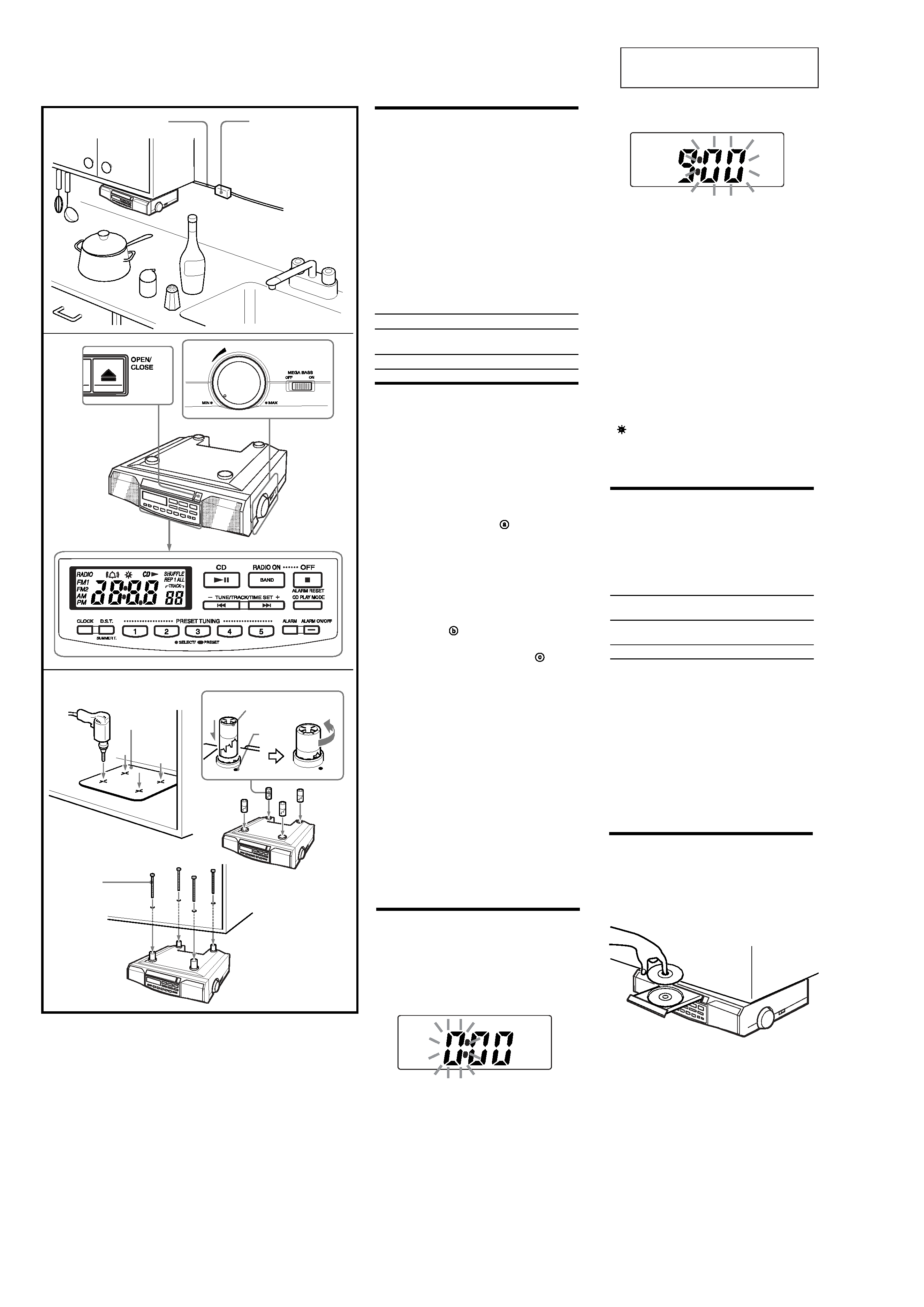
Installing the Unit
Under a Cabinet
(See Fig. A)
The unit can be installed without the spacer.
1 Mark the position of the 4 holes by
using the supplied template. Use a drill
to make the holes (size 6.5 mm dia.,
9/32 inch). (See Fig. A- )
2 When the cabinet door overhangs the
shelf and obstructs the unit, you can
adjust the unit/shelf height.
First set the L mark to the dot which
becomes the lowest position, then you
can adjust the height in 4 steps (H··L)
by turning the spacer counterclockwise.
(See Fig. A- )
3 Install the unit with the supplied
mounting screws. (See Fig. A- )
Caution
· Since the unit is very heavy, be careful when
installing the unit.
· To reduce the risk of fire, do not place any
heating or cooking appliance beneath this
unit.
· Install the unit so that its AC power cord can
be connected directly to a wall outlet. Do not
use a converter or extension cord.
· Be sure that the AC power cord has no slack
when using the unit, since the cord acts as an
FM wire antenna. If the AC power cord has
some slack, wind it up to the cord hook until
the cord has no slack.
· The unit has a built-in ferrite bar antenna for
AM radio reception. Check the condition of
AM reception before fixing in position.
· Install the unit as far as possible from a source
of noise. (for example, refrigerator, microwave
oven, fluorescent lamp, etc.)
AC power cord
Cordon d'alimentation secteur
Cord clamp
Attache de cordon
Template
Gabarit
Spacer/Pièced'écartement
L (Low)
L(Bas)
Dot
Point
Mounting screw
Vis de fixation
A
<
<
<
a
b
c
5 Repeat steps 3 and 4 to set the minute.
After setting the minute, press CLOCK to start
the counting of the seconds, and you will
hear two short beeps.
· To set the current time rapidly, hold down
TUNE/TRACK/TIME SET +
or .
· The clock system varies depending on the
model you own.
12-hour system: "AM 12:00" = midnight
24-hour system: "0:00" = midnight
· In step 5, when you press CLOCK after the
minute setting to activate the clock, the seconds
start counting from zero.
To change the display to the
daylight saving time (summer time)
indication
Press D.S.T./SUMMER T..
"
" is displayed and the time indication
changes to summer time.
To deactivate the summer time function, press
D.S.T./SUMMER T.
again.
Changing
AM Channel Step
The AM channel step differs depending on areas.
The channel step of this unit is factory-set to
9 kHz or 10 kHz to match the frequency
allocation system of the country as listed.
You can change the channel step.
Area
Channel step
AM
FM
North and South
American countries
10 kHz
0.1 MHz
Other countries
9 kHz
0.05 MHz
1 Press OFF to turn off the power.
2 While holding down OFF, keep
pressing PRESET 1 for more than 5
seconds. Two short beeps will sound,
and the AM channel step will be
changed.
If you proceed step 2 again, the channel
step changes again.
· When the AM channel step is changed, the
preset stations will be erased.
· When the AM channel step is changed, the FM
channel step is also changed.
Setting the Clock
1 Plug in the clock radio.
The display will flash "AM 12:00" or "0:00".
2 Press CLOCK for a few seconds.
You will hear a beep and the hour will start
to flash in the display.
3 Press TUNE/TRACK/TIME SET + or
until the correct hour appears in the
display.
Playing a CD
An 8 cm (3-inch) CD can be played without an
adaptor.
1 Press Z OPEN/CLOSE and place a CD
on the disc tray.
2 Press Z OPEN/CLOSE to close the disc
tray.
3 Press CD u.
The player plays all the tracks once.
4 Press CLOCK once.
The minute will flash.
5
Tuning in to a preset station
1 Press RADIO ON·BAND to turn on the
radio.
2 Press RADIO ON·BAND to select the
band.
3 Press the PRESET TUNING button
lightly where the desired station is stored.
4 Adjust the volume using VOLUME .
After a few seconds, the display returns to
the current time but the preset button
number remains.
Note
When the PRESET TUNING buttons (1-5) are
pressed lightly, the radio station that is preset
will be selected. When they are pressed for a
while, the station that is on will be newly preset.
Useful Functions
To Obtain Powerful Bass
Switch MEGA BASS to ON .
The "MEGA BASS" system produces a powerful
bass sound.
Setting the Alarm
Before setting the alarm, make sure to set the
clock (see "Setting the Clock").
To Set the Alarm Time
1 Turn off the radio.
2 Press ALARM for a few seconds.
You will hear a beep and the hour will start
to flash in the display.
3 Press TUNE/TRACK/TIME SET + or
until the desired time appears in the
display.
4 Press ALARM once.
The minutes starts to flash.
5 Repeat steps 3 and 4 to set the minute.
Two short beeps will confirm the setting, and
the display will show the current time.
When TUNE/TRACK/TIME SET + or is held
down, the displayed time initially changes in
one-minute steps, and after about a second,
switches to ten-minute steps.
To Check the Alarm
Time
Press ALARM .
The display shows the alarm time for a few
seconds and then returns to show the current
time.
ALARM ON --
To Set the Alarm Mode
Press ALARM ON/OFF to set the alarm.
"
" will appear in the display.
When the alarm comes on at the preset time,
"
" flashes in the display.
ALARM OFF --
The alarm is turned off automatically after
59 minutes.
To Stop the Alarm
Press OFF·ALARM RESET to turn off the
alarm.
The alarm will come on again at the same time
the next day.
To Cancel the Alarm
Press ALARM ON/OFF.
"
" will disappear from the display.
Handle the disc
by its edge.
Do not touch the
surface.
Do not stick paper
or tape nor write
anything on the
surface.
4 Adjust volume using VOLUME .
* AMS = Automatic Music Sensor
** These operations are possible during both
play and pause.
· To handle compact discs
Correct
Incorrect
Note
If you press CD u when there is no disc in the
CD compartment, "00" flashes for about 5
seconds on the display and the unit turns off
automatically.
Various Modes of CD
Playback
You can play tracks repeatedly or in random
order.
Press CD PLAY MODE .
Each press changes the play mode as
follows:
To
Press
Pause
CD u
Resume play after
CD u
again
pause
Locate the beginning
.**
of the current
track (AMS*)
Locate the next
>**
track (AMS)
Go back at high speed
Hold down .**
Go forward at high
Hold down >**
speed
Locate the previous
. repeatedly**
track (AMS)
Locate the succeeding
> repeatedly**
track (AMS)
Stop play
x
Display
Play
Indication
mode
none
(normal play)
All the tracks are played once.
m
"REP 1"
(single repeat)
A single track is played repeatedly.
m
"REP ALL"
(all repeat)
All the tracks are played repeatedly.
m
"SHUFFLE"
(shuffle play)
All the tracks are played once
in random order.
m
"SHUFFLE REP"
(shuffle repeat)
All the tracks are played repeatedly
in random order.
Operating the Radio
Manual Tuning
1 Press RADIO ON·BAND to turn on the
radio.
"RADIO" appears in the display.
The display shows the band and frequency
for a few seconds and then changes back to
the current time.
2 Press RADIO ON·BAND repeatedly to
select the desired band.
Each press changes the band as follows:
* When using FM1 or FM2 preset mode, you
may listen to the radio on either mode
(See "Preset Tuning").
<
3 Use TUNE/TRACK/TIME SET + or to
tune in to the desired station.
The FM channel step is set to 0.1 MHz and
the AM channel step is set to 10 kHz (US,
Canadian models).
The FM channel step is set to 0.05 MHz* and
the AM channel step is set to 9 kHz (AEP
model).
* The FM frequency display is raised or
lowered by a step of 0.1 MHz. For example,
frequency 88.00 and 88.05 MHz is displayed
as "88.0 MHz."
Two short beeps sound when the
minimum frequency of each band is
received during tuning.
4 Adjust volume using VOLUME .
· To turn off the radio, press OFF.
· To improve radio reception
FM:
Extend the AC power cord fully to
improve FM reception.
AM:
When installing the unit, rotate the unit
horizontally for optimum reception and
then install the unit. A ferrite bar antenna
is built into the unit.
· To check the station being received, press
RADIO ON·BAND
lightly. The display shows
the band and frequency for a few seconds and
then changes back to the current time.
Preset Tuning
You can preset 10 stations in FM (5 stations in
FM1, 5 stations in FM2) and 5 stations in AM.
Presetting a Station
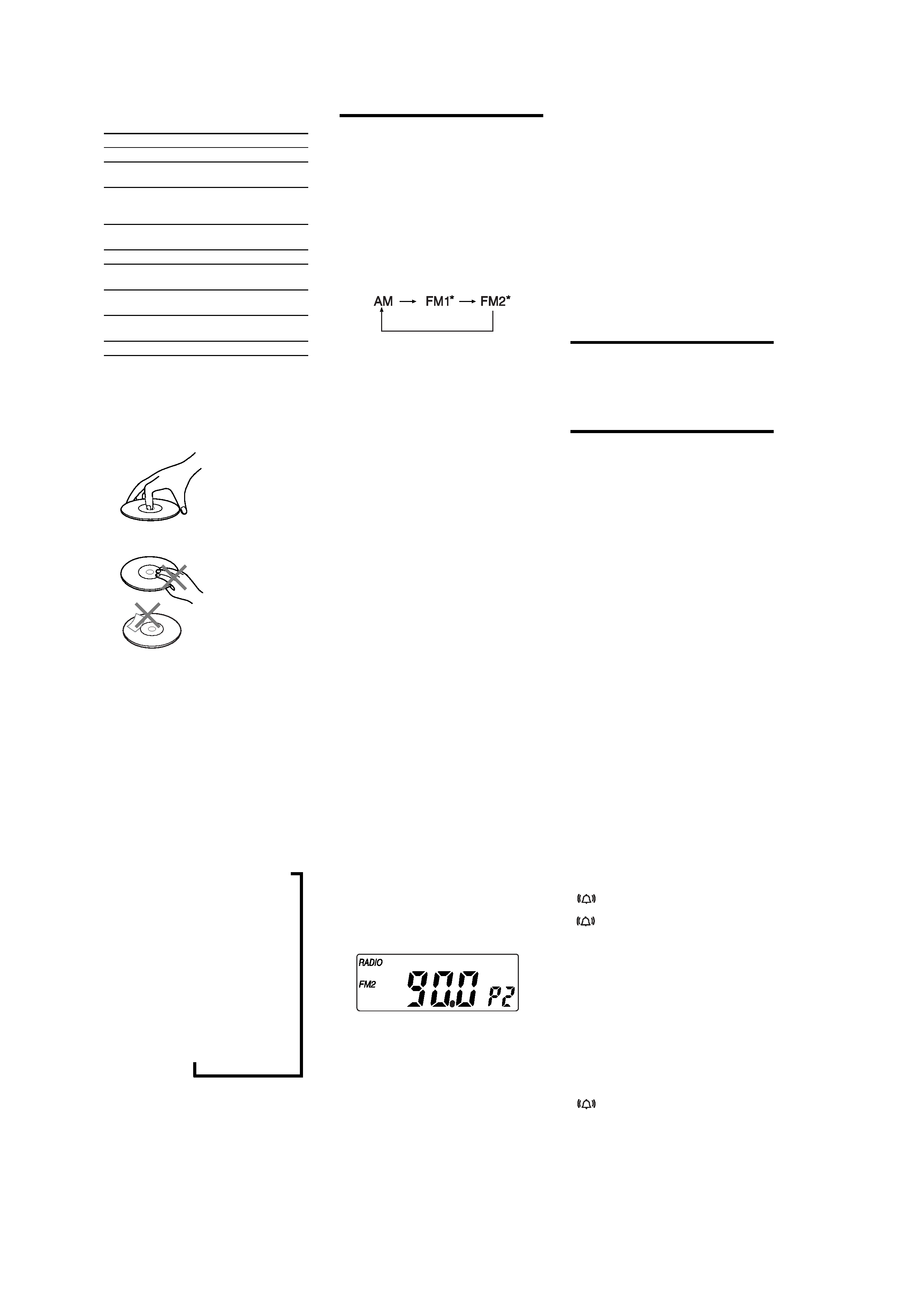
Example: To preset FM90 MHz onto preset
button 2 for FM2.
1 Press RADIO ON·BAND to turn on the
radio.
2 Press RADIO ON·BAND to select FM2.
3 Tune in to the station on FM90 MHz
(See "Manual Tuning").
4 Hold down the PRESET TUNING
button 2 until you hear two short
beeps.
The display shows the frequency for a few
seconds and then changes back to the current
time.
To change a preset station
Tune in manually to the station you want to store
and hold down the PRESET TUNING button (1-5)
until you hear two short beeps. The previously
stored station will be replaced by the new one.