MICROFILM
SERVICE MANUAL
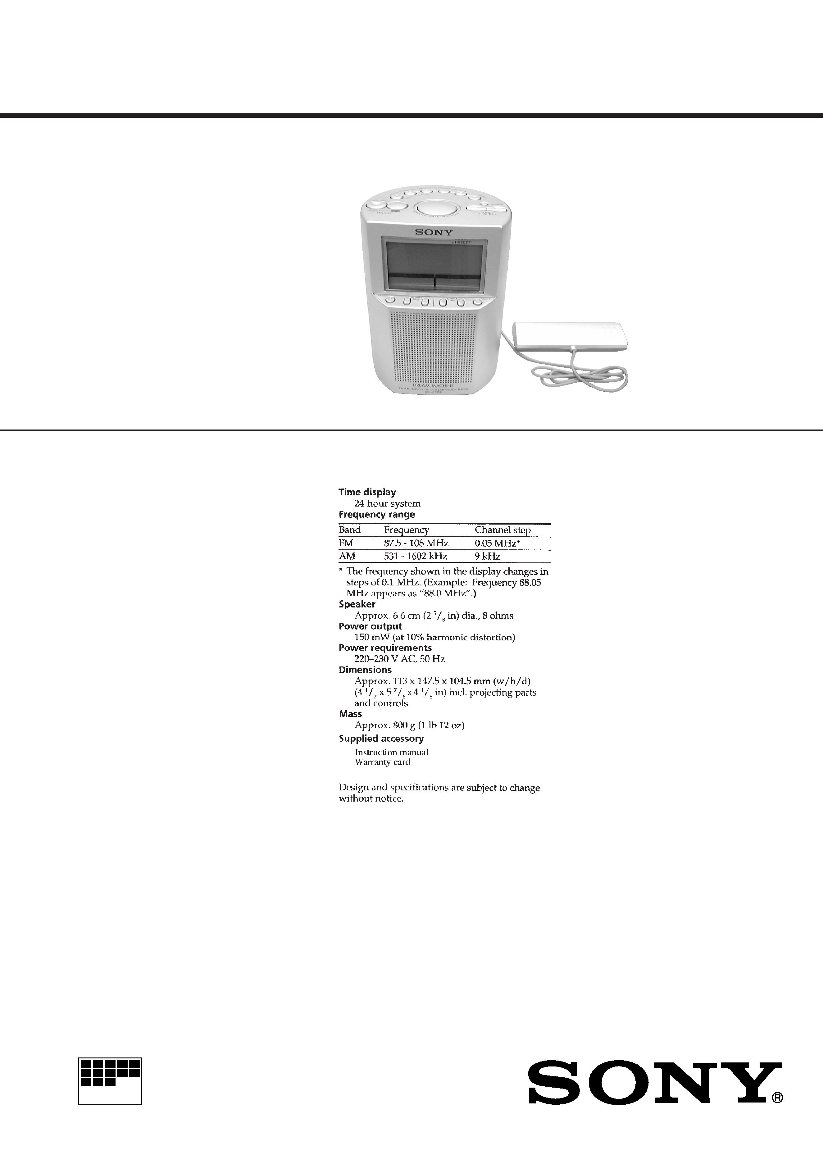
FM/AM RADIO CONTROLLED CLOCK RADIO
AEP Model
SPECIFICATIONS
ICF-C795RC
Ver 1.0 1999. 08
2
TABLE OF CONTENTS
1.
GENERAL ................................................................... 3
2.
DISASSEMBLY ......................................................... 5
3.
ELECTRICAL ADJUSTMENTS ......................... 7
4.
DIAGRAMS
4-1. Block Diagram ................................................................
9
4-2. Schematic Diagram ......................................................... 13
4-3. Printed Wiring Boards .................................................... 15
4-4. IC Pin Function Description ........................................... 18
5.
EXPLODED VIEWS ................................................ 19
6.
ELECTRICAL PARTS LIST ............................... 21
Notes on chip component replacement
· Never reuse a disconnected chip component.
· Notice that the minus side of a tantalum capacitor may be dam-
aged by heat.
SAFETY-RELATED COMPONENT WARNING!!
COMPONENTS IDENTIFIED BY MARK
! OR DOTTED
LINE WITH MARK
! ON THE SCHEMATIC DIAGRAMS
AND IN THE PARTS LIST ARE CRITICAL TO SAFE
OPERATION. REPLACE THESE COMPONENTS WITH
SONY PARTS WHOSE PART NUMBERS APPEAR AS
SHOWN IN THIS MANUAL OR IN SUPPLEMENTS PUB-
LISHED BY SONY.
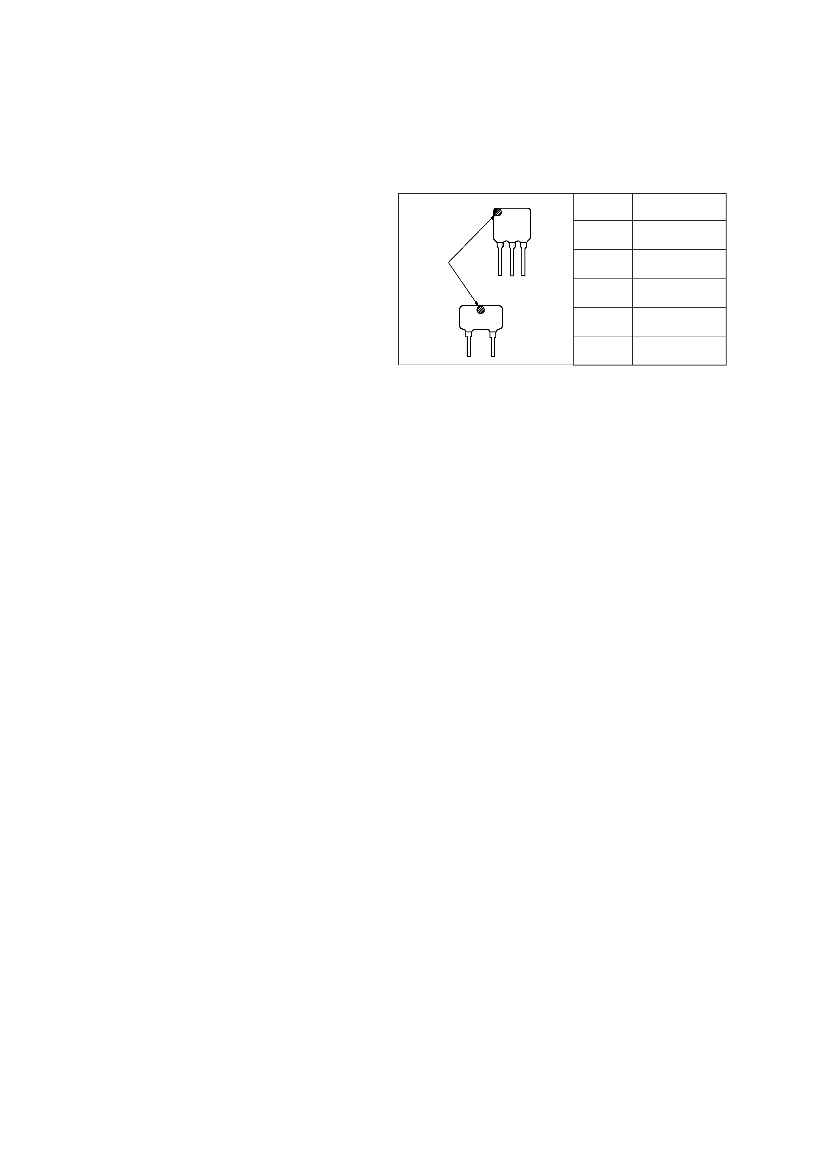
CF2
CF3
mark
Mark
Center frequency
red
10.70 MHz
blue
10.67 MHz
orange
10.73 MHz
black
10.64 MHz
white
10.76 MHz
HOW TO CHANGED THE CERAMIC FILTERS
This model is used two ceramic filters of CF2 and CF3.
You must use same type of color marked ceramic filters in order
to meet same specifications.
Therefore, the ceramic filter must be changed two pieces together
since it's supply two pieces in one package as a spare parts.
3
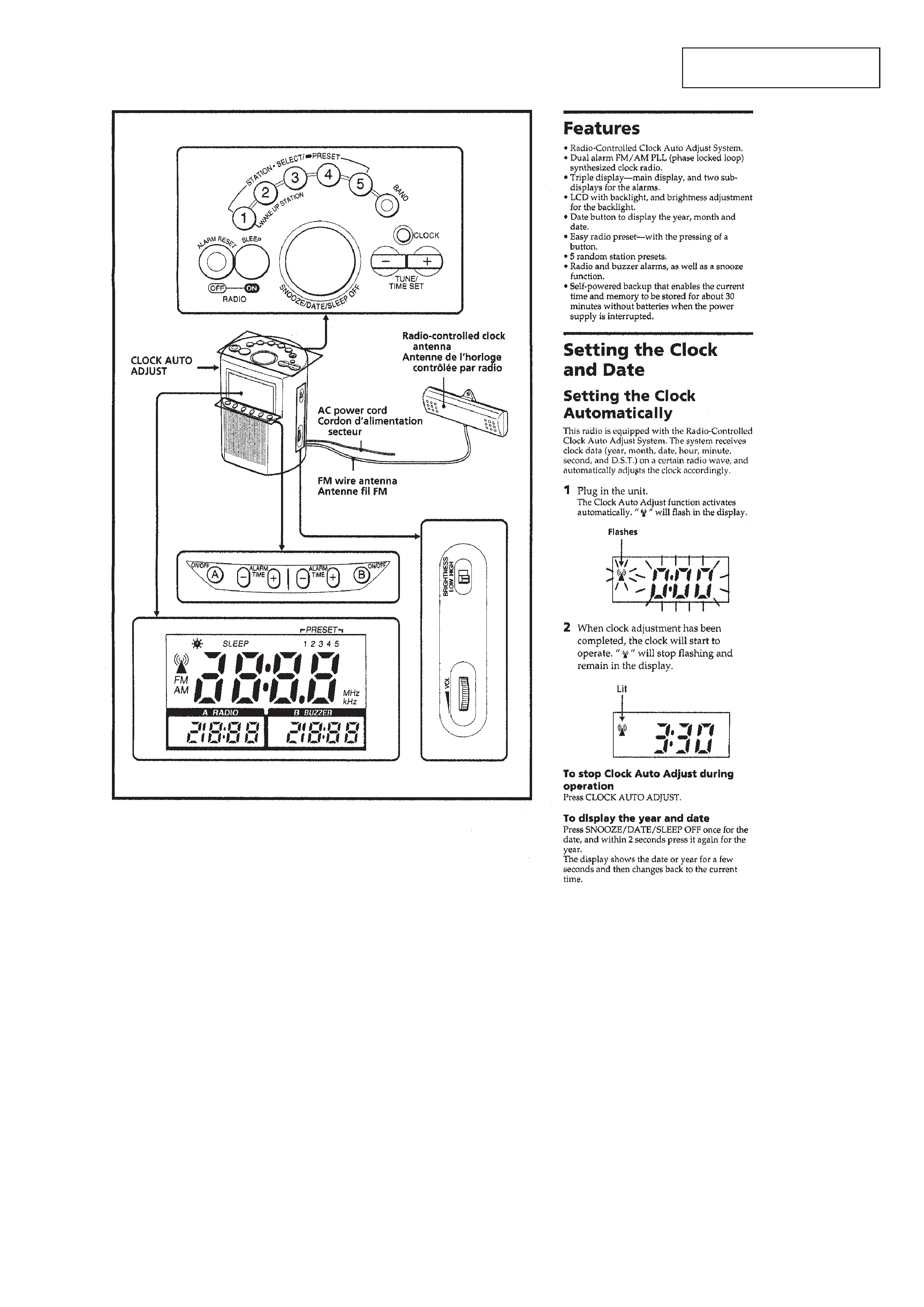
SECTION 1
GENERAL
This section is extracted from
instruction manual.
4
5
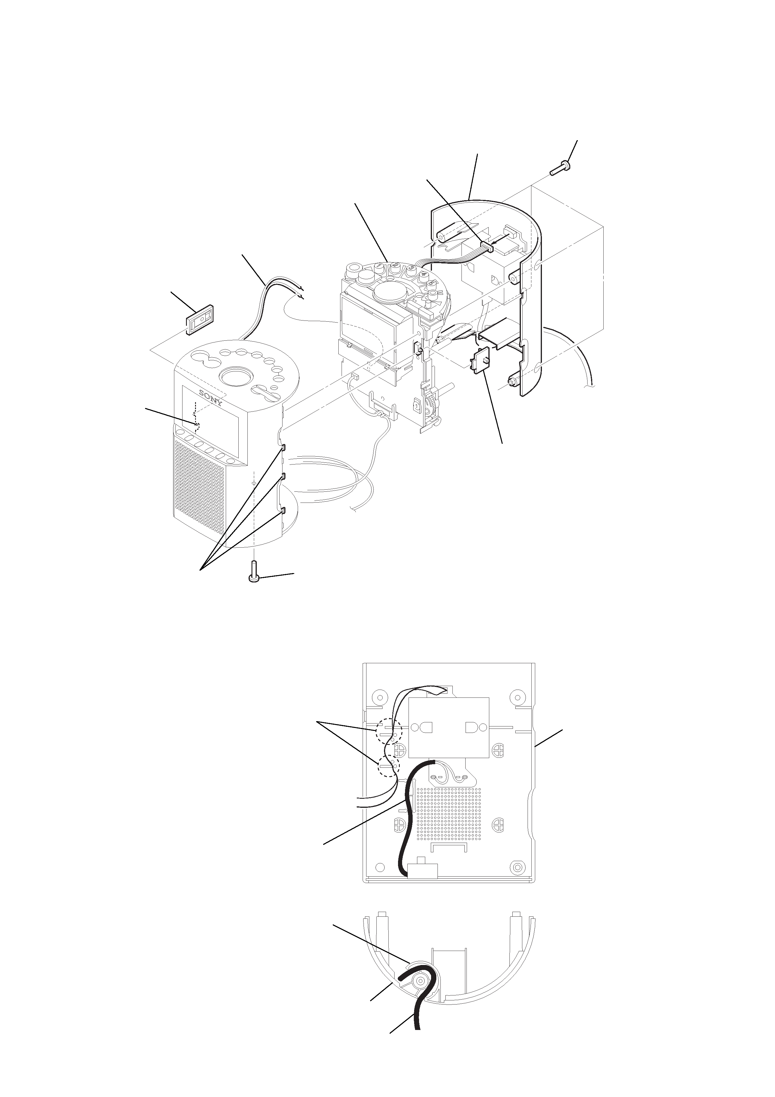
CHASSIS ASSY
Note: Follow the disassembly procedure in the numerical order given.
SECTION 2
DISASSEMBLY
2
claw
2
three claws
1
screw (P3
× 14)
1
four screws (P3
× 14)
3
rear cabinet
4
connector
(CN301)
7
chassis assy
5
Break the soldering of
speaker lead.
6
button (DST)
6
knob (brightness)
POWER CORD SETTING
Set the power cord as illustrated below,
then install the cabinet.
rear cabinet
power cord
boss
rear cabinet
power cord
Put the secondary flat cable
between bosses to fix.