MICROFILM
SERVICE MANUAL
ICF-C470
FM/AM CLOCK RADIO
ICF-C470L
FM/MW/LW 3 BAND CLOCK RADIO
US Model
Canadian Model
E Model
Australian Model
ICF-C470
AEP Model
ICF-C470/C470L
UK Model
ICF-C470L
SPECIFICATIONS
ICF-C470/C470L
Photo: ICF-C470
Ver 1.1 1999. 06
With SUPPLEMENT 1
(9-926-981-81)
2
TABLE OF CONTENTS
1.
GENERAL ................................................................... 3
2.
DISASSEMBLY ......................................................... 4
3.
DIAL POINTER SETTING ..................................... 5
4.
POWER CORD SETTING ..................................... 6
5.
ELECTRICAL ADJUSTMENTS .......................... 7
6.
DIAGRAMS
6-1. Block Diagram ................................................................
9
6-2. Printed Wiring Boards (ICF-C470) ................................ 11
6-3. Schematic Diagram (ICF-C470) ..................................... 13
6-4. Printed Wiring Boards (ICF-C470L) .............................. 15
6-5. Schematic Diagram (ICF-C470L) .................................. 17
7.
EXPLODED VIEWS ................................................ 20
8.
ELECTRICAL PARTS LIST ............................... 22
ATTENTION AU COMPOSANT AYANT RAPPORT
À LA SÉCURITÉ!
LES COMPOSANTS IDENTIFIÉS PAR UNE MARQUE
!
SUR LES DIAGRAMMES SCHÉMATIQUES ET LA LISTE
DES PIÈCES SONT CRITIQUES POUR LA SÉCURITÉ
DE FONCTIONNEMENT. NE REMPLACER CES COM-
POSANTS QUE PAR DES PIÈCES SONY DONT LES
NUMÉROS SONT DONNÉS DANS CE MANUEL OU
DANS LES SUPPLÉMENTS PUBLIÉS PAR SONY.
SAFETY-RELATED COMPONENT WARNING!!
COMPONENTS IDENTIFIED BY MARK
! OR DOTTED
LINE WITH MARK
! ON THE SCHEMATIC DIAGRAMS
AND IN THE PARTS LIST ARE CRITICAL TO SAFE
OPERATION. REPLACE THESE COMPONENTS WITH
SONY PARTS WHOSE PART NUMBERS APPEAR AS
SHOWN IN THIS MANUAL OR IN SUPPLEMENTS PUB-
LISHED BY SONY.
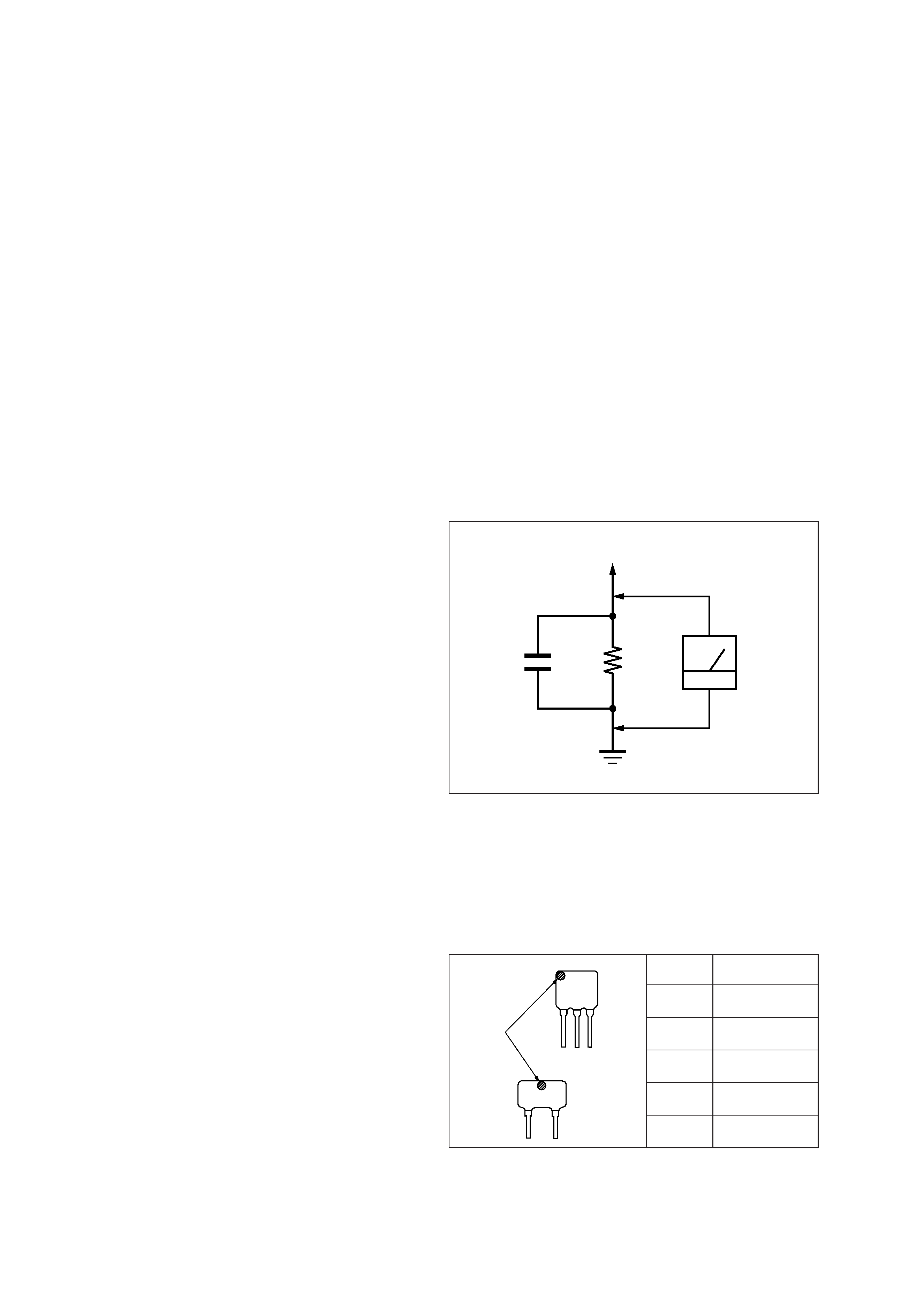
HOW TO CHANGED THE CERAMIC FILTERS
This model is used two ceramic filters of CF2 and CF3.
You must used same type of color marked ceramic filters in order
to meet same specifications.
Therefore, the ceramic filter must changed two pieces together
since it's supply two pieces in one package as a spare parts.
CF2
CF3
mark
Mark
Center frequency
red
10.70 MHz
blue
10.67 MHz
orange
10.73 MHz
black
10.64 MHz
white
10.76 MHz
Notes on chip component replacement
· Never reuse a disconnected chip component.
· Notice that the minus side of a tantalum capacitor may be dam-
aged by heat.
SAFETY CHECK-OUT
After correcting the original service problem, perform the follow-
ing safety check before releasing the set to the customer:
Check the antenna terminals, metal trim, "metallized" knobs,
screws, and all other exposed metal parts for AC leakage.
Check leakage as described below.
LEAKAGE TEST
The AC leakage from any exposed metal part to earth ground and
from all exposed metal parts to any exposed metal part having a
return to chassis, must not exceed 0.5 mA (500 microampers.).
Leakage current can be measured by any one of three methods.
1. A commercial leakage tester, such as the Simpson 229 or RCA
WT-540A. Follow the manufacturers' instructions to use these
instruments.
2. A battery-operated AC milliammeter. The Data Precision 245
digital multimeter is suitable for this job.
3. Measuring the voltage drop across a resistor by means of a
VOM or battery-operated AC voltmeter. The "limit" indica-
tion is 0.75 V, so analog meters must have an accurate low-
voltage scale. The Simpson 250 and Sanwa SH-63Trd are ex-
amples of a passive VOM that is suitable. Nearly all battery
operated digital multimeters that have a 2 V AC range are suit-
able. (See Fig. A)
Fig. A.
Using an AC voltmeter to check AC leakage.
1.5 k
0.15
µF
AC
voltmeter
(0.75 V)
To Exposed Metal
Parts on Set
Earth Ground
3
SECTION 1
GENERAL
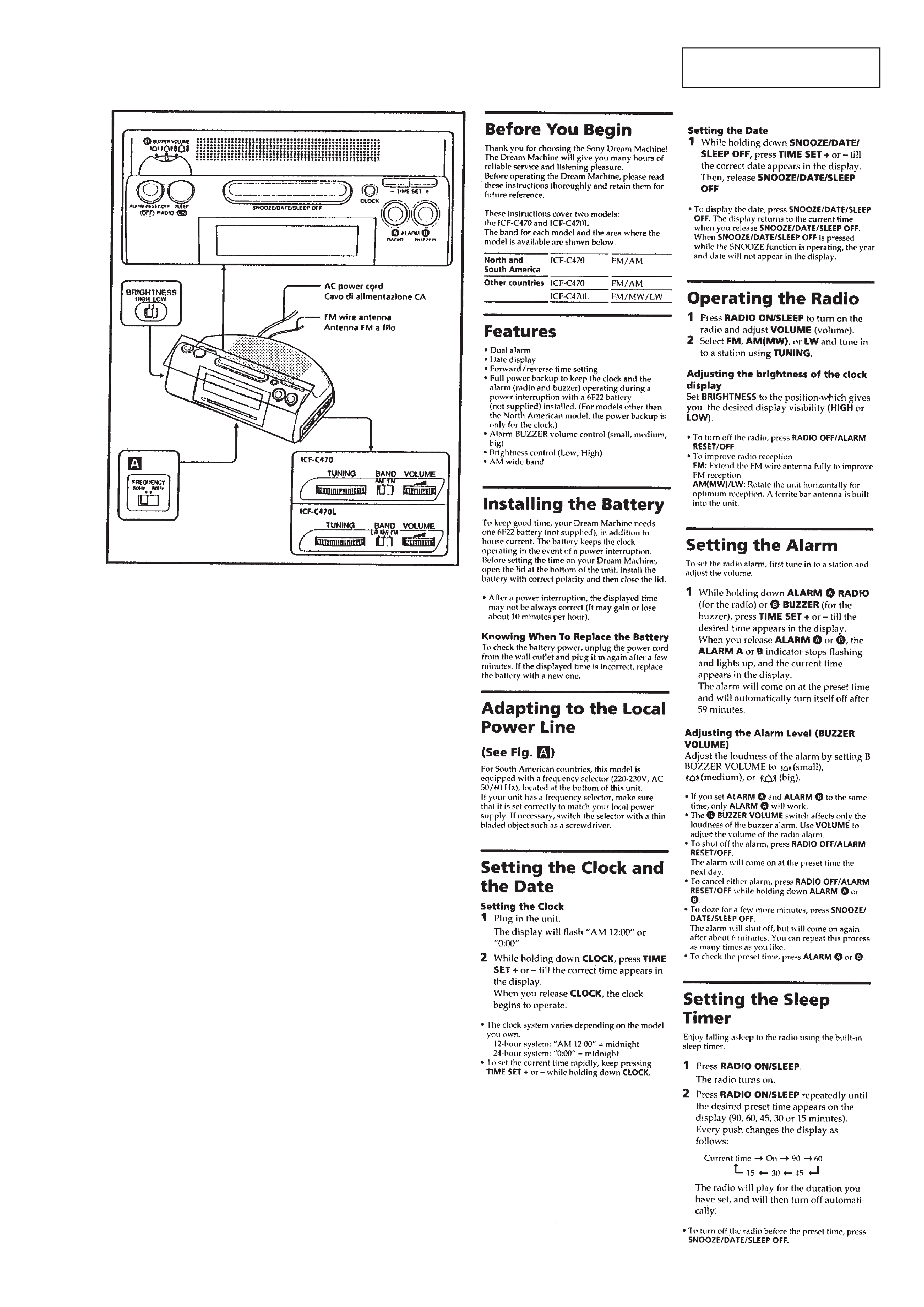
This section is extracted from
instruction manual.
4
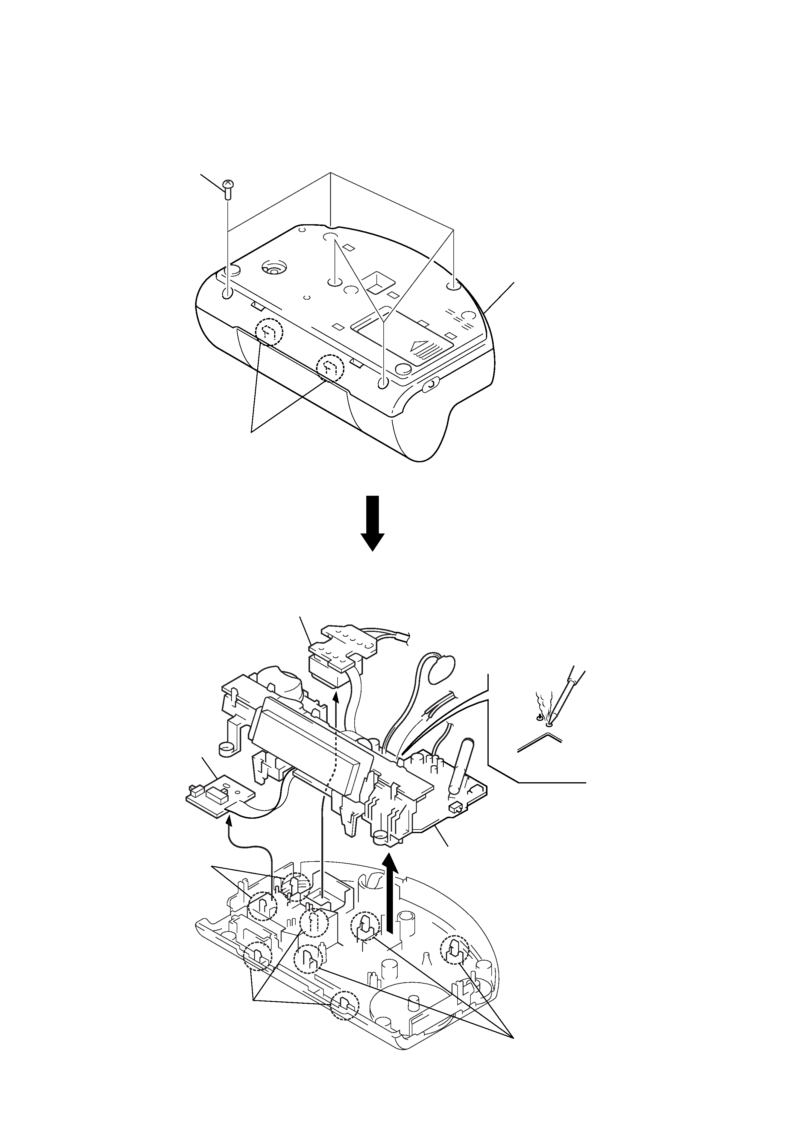
CABINET (LOWER)
MAIN BLOCK
Note: Follow the disassembly procedure in the numerical order given.
SECTION 2
DISASSEMBLY
1 five screws
(P3
×14)
2 two claws
3 cabinet (lower)
1 power transformer
5 buzzer board
4 two claws
2 three claws
for chassis
2 three claws
for PWB
3 main block
6 Break the soldering
of speaker lead.
5
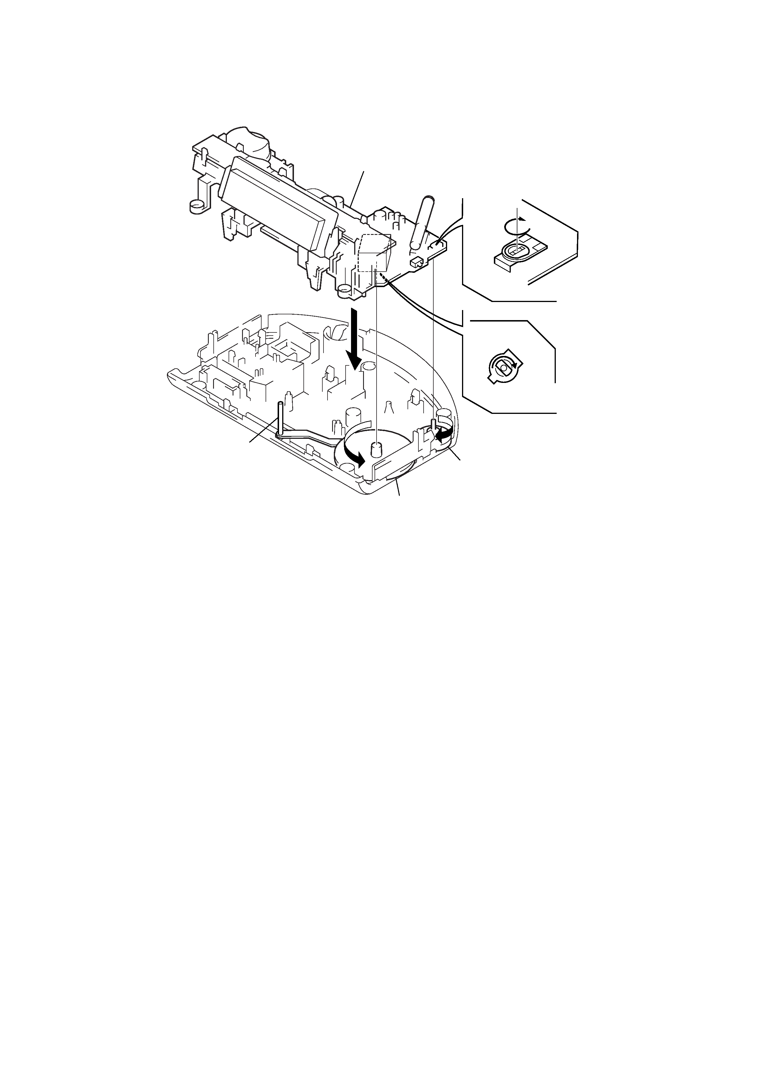
SECTION 3
DIAL POINTER SETTING
5 Install the MAIN board.
4 Turn VR1 to the
arrow
D direction fully.
3 Turn shaft of CV1 to the
arrow
C direction fully.
BOTTOM VIEW
2 Turn the knob (VOL) to the
arrow
B direction fully.
1 Turn the knob (tuning) to the
arrow
A direction fully.
dial pointer
A
B
C
D
Note: Follow the assembly procedure in the numerical order given.