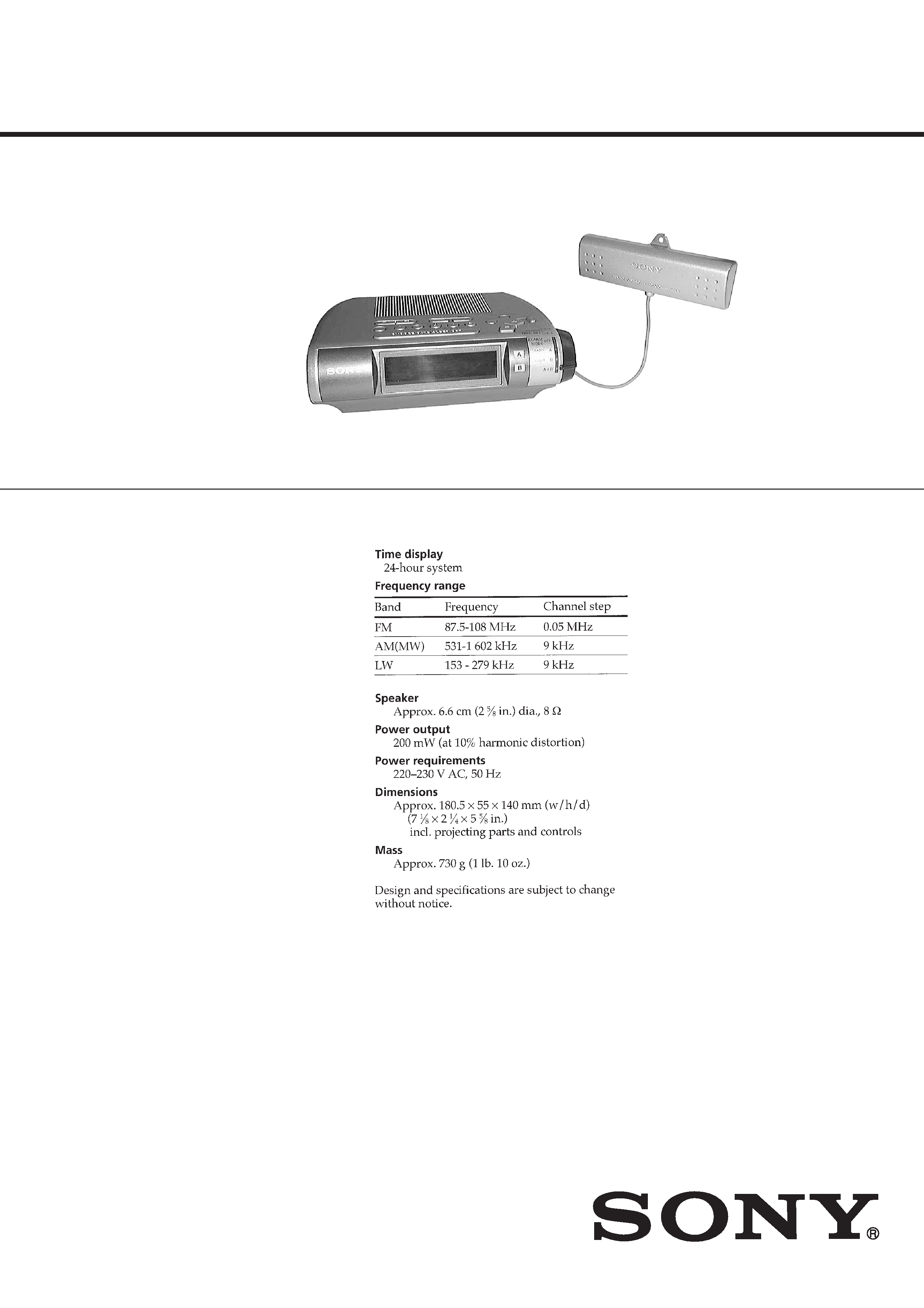
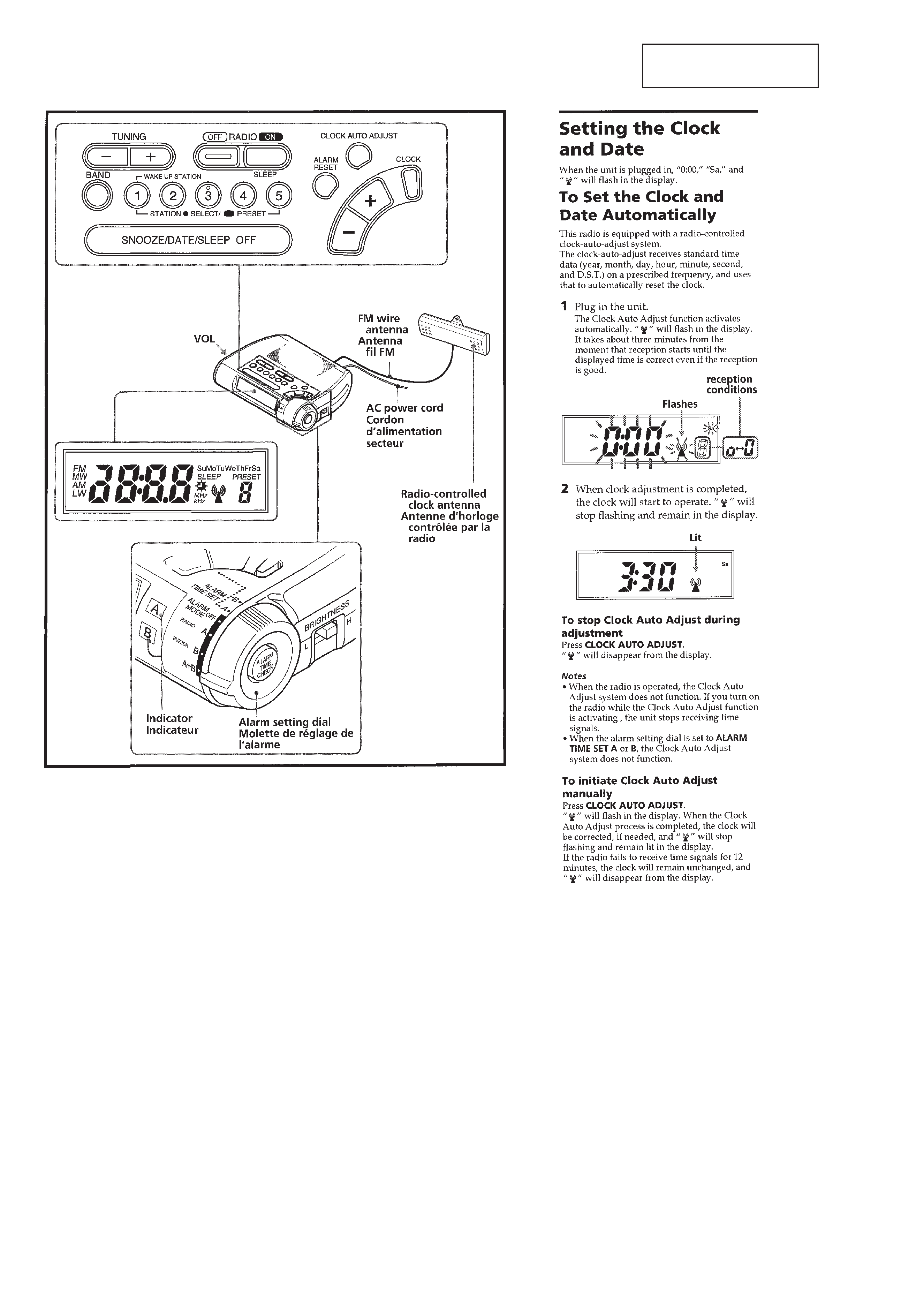
ICF-C255RC
AEP Model
SERVICE MANUAL
FM/MW/LW RADIO CONTROLLED CLOCK RADIO
SPECIFICATIONS
Ver 1.0 2000. 05
-- 2 --
SECTION 1
GENERAL
This section is extracted
from instruction manual.
1.
Check the area of your repair for unsoldered or poorly-soldered
connections. Check the entire board surface for solder splashes
and bridges.
2.
Check the interboard wiring to ensure that no wires are
"pinched" or contact high-wattage resistors.
3.
Look for unauthorized replacement parts, particularly
transistors, that were installed during a previous repair. Point
them out to the customer and recommend their replacement.
4.
Look for parts which, through functioning, show obvious signs
of deterioration. Point them out to the customer and
recommend their replacement.
5.
Check the B+ voltage to see it is at the values specified.
6.
Flexible Circuit Board Repairing
· Keep the temperature of the soldering iron around 270°C
during repairing.
· Do not touch the soldering iron on the same conductor of the
circuit board (within 3 times).
· Be careful not to apply force on the conductor when soldering
or unsoldering.
SAFETY CHECK-OUT
After correcting the original service problem, perform the following
safety checks before releasing the set to the customer.
-- 3 --
-- 4 --
SECTION 2
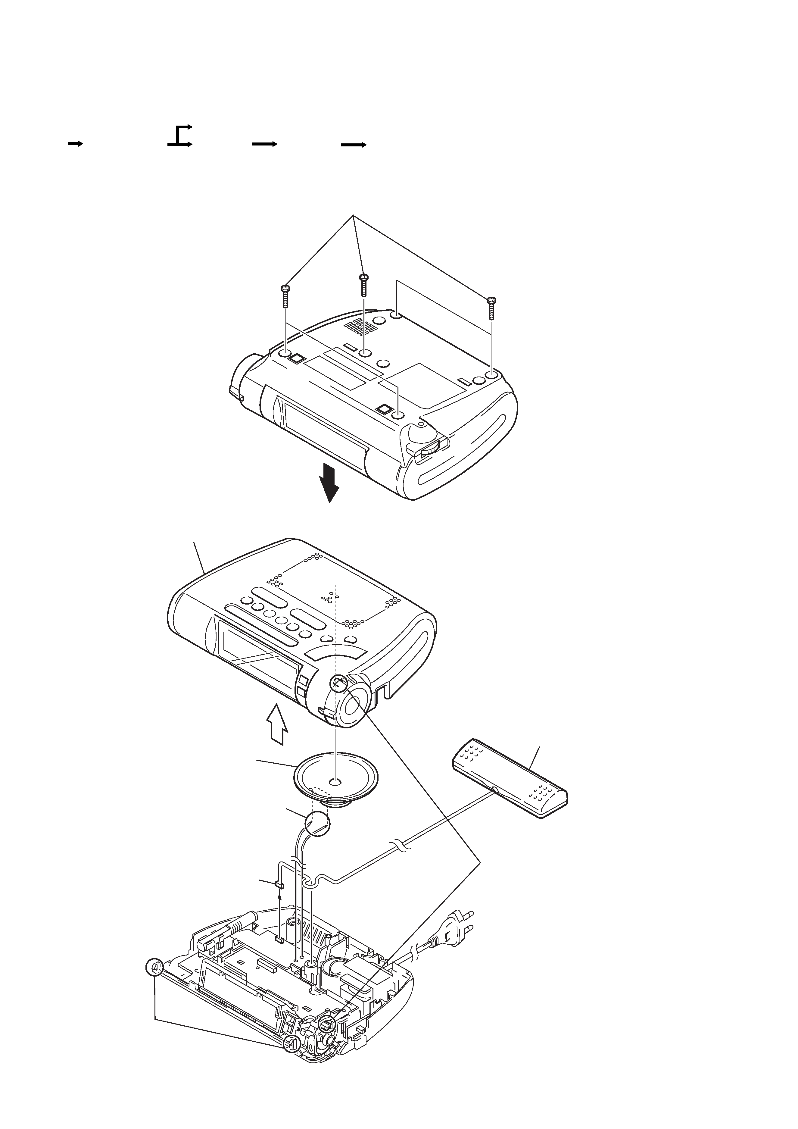
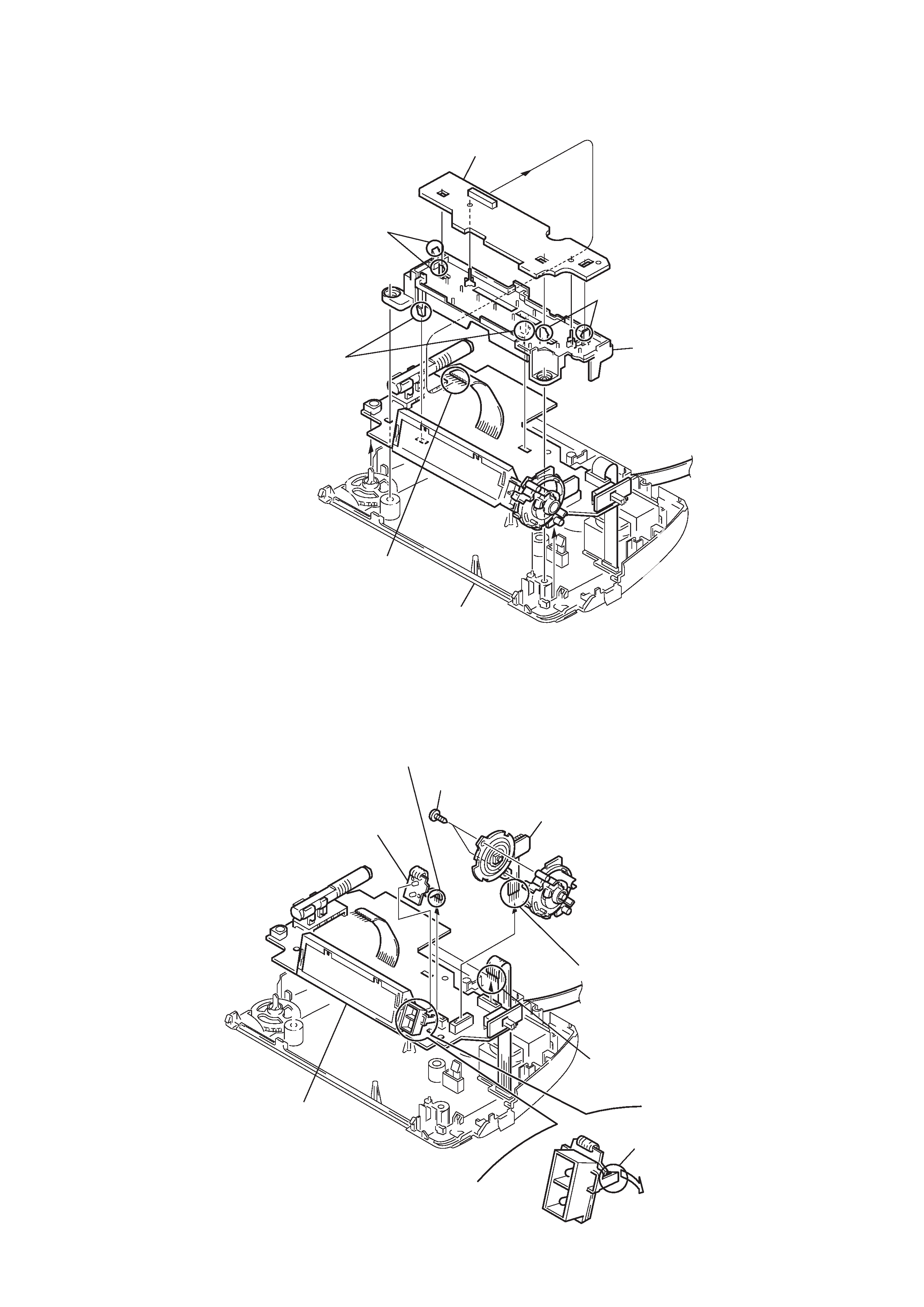
DISASSEMBLY
Note :
Follow the disassembly procedure in the numerical order given.
· The equipment can be removed using the following procedure.
Key board
Ferrite rod antenna board
Cabinet (upper)
Set
Main board
Power board
2-1.
CABINET (UPPER)
S
4
Cabinet (upper)
6
Speaker
2
Two claws
7
Box assy, ANT
connector
8
Box assy, ANT
5
Remove the two solderings.
3
1
Five screws (M3
× 14)
Precaution when attaching
the cabinet (upper).
Align the button (alarm) with
knob of the dial (alarm) assembly
to attach it.
-- 5 --
2-2.
KEY BOARD
1
Two claws
5
Two claws
2
Two claws
6
Chassis
4
Key board
3
Connector (CN200)
7
Cabinet (lower)
2-3.
MAIN BOARD
8
Main board
6
LED board
3
Alarm dial board
4
Claw
7
Connector (CN150)
5
Connector (CN2)
1
Connector (CN201)
2
Two screws (BTP 2
× 8)