1
SERVICE MANUAL
Canadian Model
E Model
Australian Model
Chinese Model
ICF-303
AEP Model
ICF-303/303L
ICF-303/303L
FM/AM RADIO
ICF-303
FM/LW RADIO
ICF-303L
MICROFILM
Photo: ICF-303
SPECIFICATIONS
Frequency range:
Central and East European model
Band
ICF-303
FM
65 - 108 MHz
AM
530 - 1605 kHz
Italian model
Band
ICF-303
FM
87.5 - 108 MHz
AM
526.5 - 1606.5 kHz
Other countries model
Band
ICF-303
ICF303L
FM
87.5 - 108 MHz
87.5 - 108 MHz
AM
530 - 1605 kHz
--
LW
--
153 - 255 kHz
Speaker
Approx. 6.6 cm (2 5/8 inches) dia., 8
Output
@ (earphone) jack (minijack)
Power output
100 mW (at 10 % harmonic distortion)
Power requirements
3 V DC, two R6 (size AA) batteries
3 V DC, two LR6 (size AA) batteries
Dimensions
Approx. 156.9
× 82.5 × 41.1 mm (w/h/d)
(6 1/4
× 3 1/4 × 1 5/8 inches) incl. projecting parts
and controls
Mass
Approx. 309.5 g (10.9 oz) incl. batteries
Supplied accessories
Operating instructions (1)
Design and specifications are subject to change without
notice.
Features
· Compact radio
· TUNE indicator for easy tuning
Ver 1.0 1999. 07
2
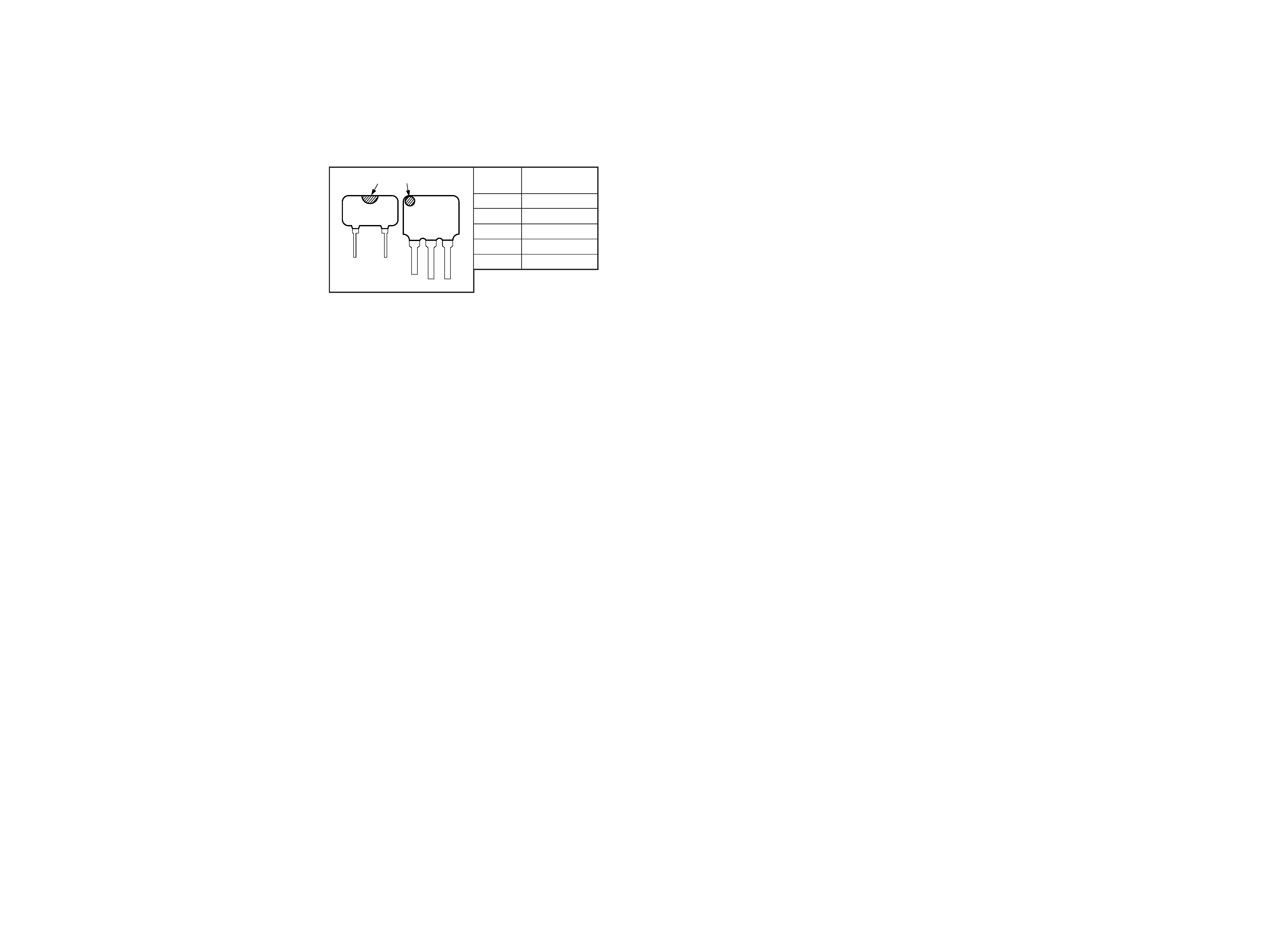
mark
Center
Frequency
red
10.70 MHz
blue
10.67 MHz
orange
10.73 MHz
black
10.64 MHz
white
10.76 MHz
HOW TO CHANGE THE CERAMIC FILTERS
This model is used two ceramic filters of CF1 and CF3.
You must use same type of color marked ceramic filters in order to
meet same specifications.
Therefore, the ceramic filter must change two pieces together since
it's supply two pieces in one package as a spare parts.
mark
mark
CF3
CF1
Notes on Chip Component Replacement
· Never reuse a disconnected chip component.
· Notice that the minus side of a tantalum capacitor may be
damaged by heat.
3
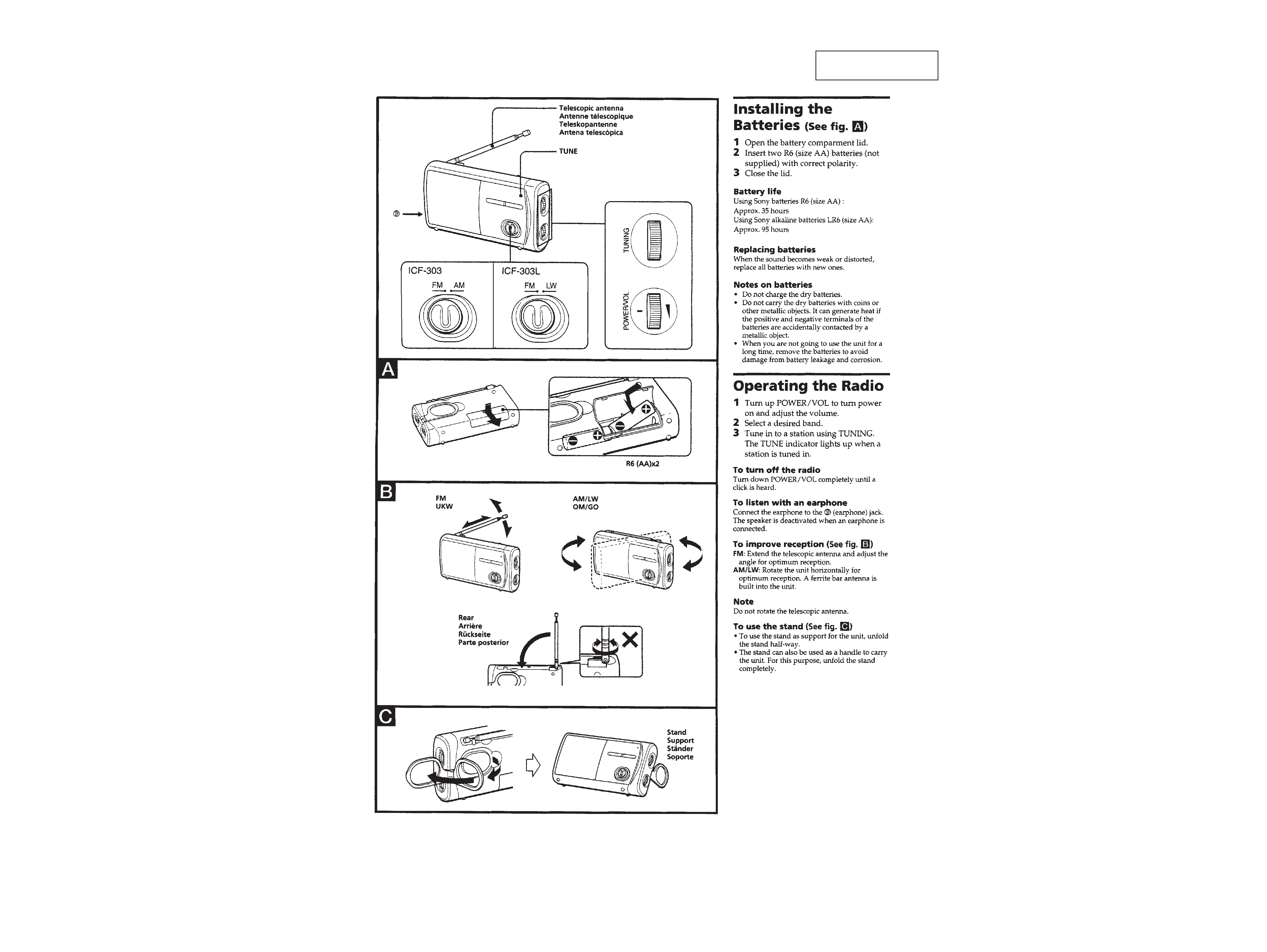
SECTION 1
GENERAL
This section is extracted
from instruction manual.
4
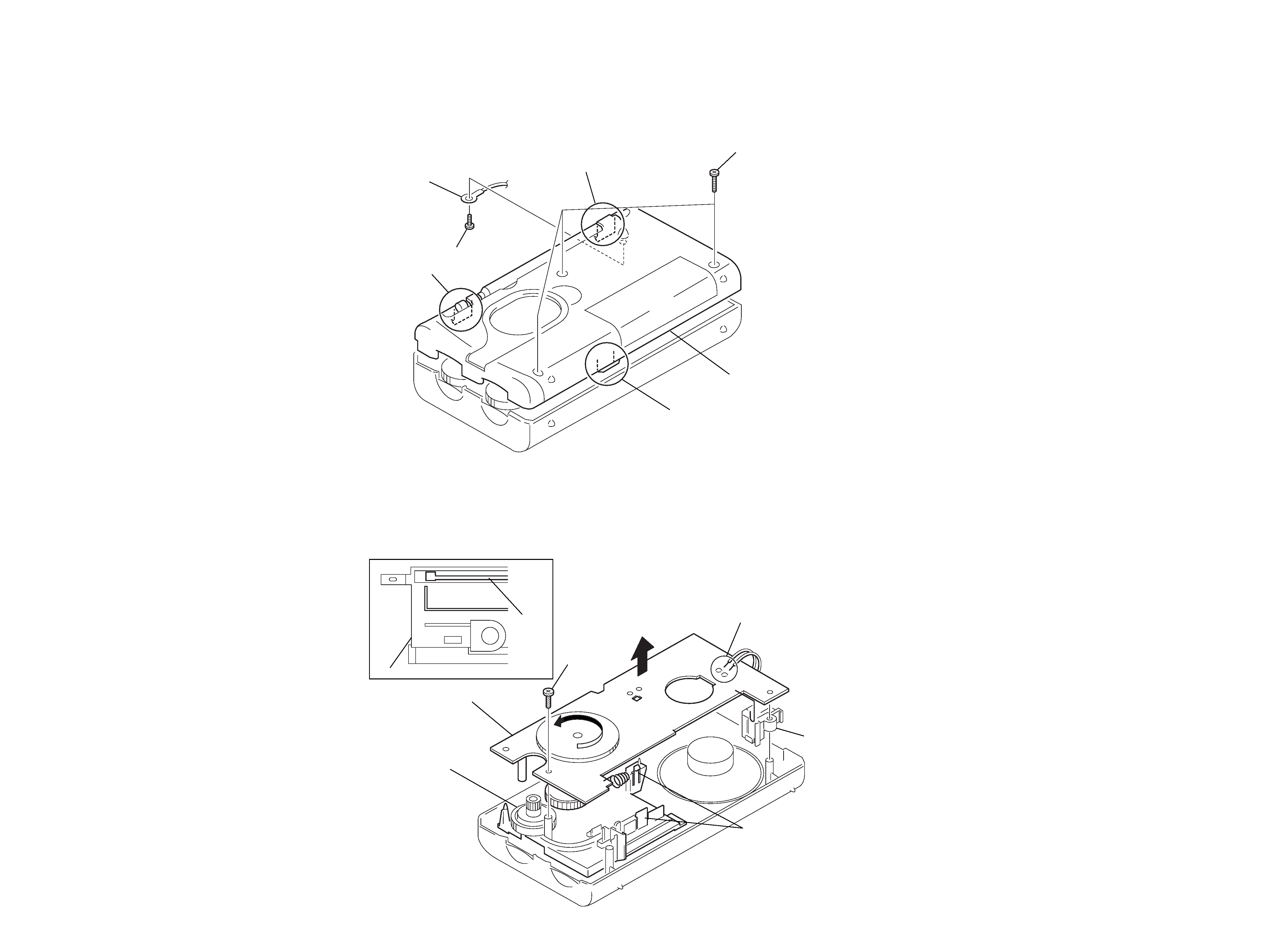
1 Unsolder the 2 places.
2
3 screw (2x8)
4 claws
5 chassis assy
6 holder, jack
7 MAIN board
chassis
rack
A
Note : Follow the disassembly procedure in the numerical order given.
2-1. CABINET (REAR) ASSY
2-2. MAIN BOARD
SECTION 2
DISASSEMBLY
1 screws +P 2.6x12
5 screws B 1.7x4
6 lug 2.6
7 cabinet (REAR) assy
2 claw
3 claw
4 claw
· Setting the Pointer
1. Turn the gear (tuning capacitor) in the direction of
A until it is stopped.
2. Place the rack as shown in the figure.
3. Mount the pointer.
Put the lead-wire
antenna close to
the set.
AM RF signal
generator
400Hz, 30%
AM modulation
Output level: as low as possible
16
set
earphone jack (EPJ1)
level meter
5
6
· Repeat the procedures in each adjustment several times, and the
frequency coverage and tracking adjustments should be finally
done by the trimmer capacitors.
LW FREQUENCY COVERAGE ADJUSTMENT
Adjust for a maximum reading on level meter
L5
145 kHz
CT1
265 kHz
LW TRACKING ADJUSTMENT
Adjust for a maximum reading on level meter
L1
160 kHz
CT2
240 kHz
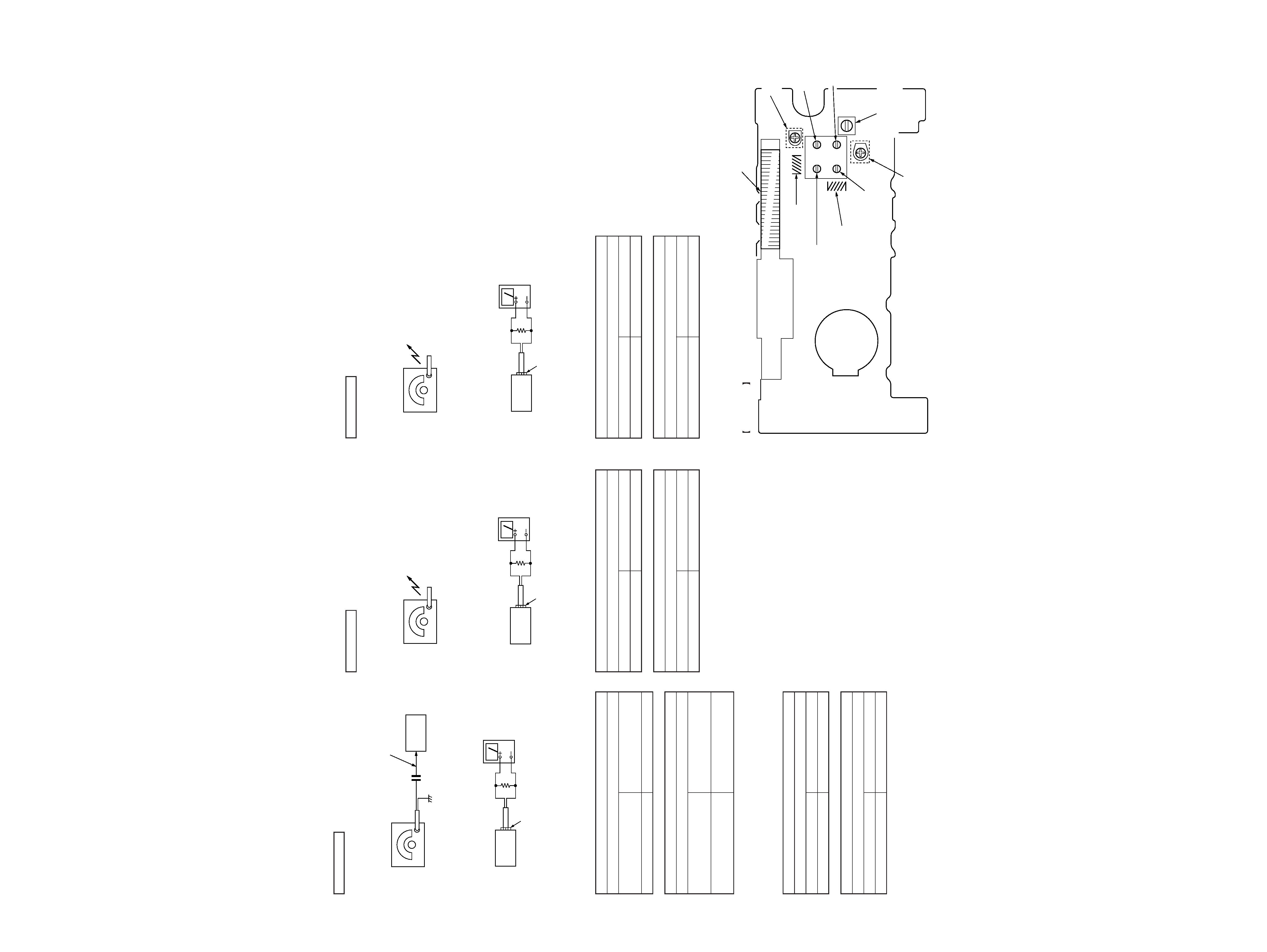
Adjustment Location: MAIN BOARD
ICF-303L:
LW SECTION
BAND switch : LW
(303L)
(303L)
CT2
LW TRACKING( 303L)
ADJUSTMENT
CT1-1
AM TRACKING (303)
ADJUSTMENT
CT1-4
AM FREQUENCY
COVERAGE (303)
ADJUSTMENT
L2
FM TRACKING
ADJUSTMENT
L4
FM FREQUENCY
COVERAGE
ADJUSTMENT
L5
AM FREQUENCY COVERAGE (303)
LW FREQUENCY COVERAGE (303L)
ADJUSTMENT
CT1-2
FM TRACKING
ADJUSTMENT
MAIN BOARD
(COMPONENT SIDE)
CT1
LW FREQUENCY
COVERAGE (303L)
ADJUSTMENT
CT1-3
FM FREQUENCY
COVERAGE
ADJUSTMENT
L1
AM TRACKING (303)
LW TRACKING (303L)
ADJUSTMENT
16
set
earphone jack (EPJ1)
level meter
Put the lead-wire
antenna close to
the set.
AM RF signal
generator
400Hz, 30%
AM modulation
Output level: as low as possible
· Repeat the procedures in each adjustment several times, and the
frequency coverage and tracking adjustments should be finally
done by the trimmer capacitors.
ICF-303:
FM FREQUENCY COVERAGE ADJUSTMENT
Adjust for a maximum reading on level meter
L4
86.5 (87.35)
<64> MHz
CT1-3
109.5 (108.25) MHz
FM TRACKING ADJUSTMENT
Adjust for a maximum reading on level meter
L2
86.5 (87.35)
<68> MHz
CT1-2
109.5 (108.25)
<102> MHz
NOTE : (
) : Italian model
<
> : East European model
ICF-303L:
FM FREQUENCY COVERAGE ADJUSTMENT
Adjust for a maximum reading on level meter
L4
86.5 MHz
CT1-3
109.5 MHz
FM TRACKING ADJUSTMENT
Adjust for a maximum reading on level meter
L2
86.5 MHz
CT1-2
109.5 MHz
SECTION 3
ELECTRICAL ADJUSTMENTS
FM SECTION
BAND switch : FM
telescopic
antenna terminal
0.01
µF
FM RF signal
generator
400Hz, 30% FM modulation
frequency deviation
±22.5kHz
Output level: as low as possible
set
16
set
earphone jack (EPJ1)
level meter
· Repeat the procedures in each adjustment several times, and the
frequency coverage and tracking adjustments should be finally
done by the trimmer capacitors.
AM FREQUENCY COVERAGE ADJUSTMENT
Adjust for a maximum reading on level meter
L5
520 (516.5) kHz
CT1-4
1,650 (1,631.5) kHz
AM TRACKING ADJUSTMENT
Adjust for a maximum reading on level meter
L1
600 (620) kHz
CT1-1
1,400 kHz
NOTE : no mark : (
) : Italian model
ICF-303:
AM SECTION
BAND switch : AM