SERVICE MANUAL
Sony Corporation
Connect Company
Published by Sony Engineering Corporation
US Model
UK Model
Chinese Model
Korea Model
IC RECORDER
9-879-994-01
2005L04-1
© 2005. 12
Ver. 1.0 2005. 12
SPECIFICATIONS
ICD-P320
Recording media
Built-in flash memory 64 MB,
Monaural recording
Recording time
HQ:
7 hours 20 minutes
SP:
19 hours 35 minutes
LP:
32 hours 10 minutes
Frequency range
HQ:
260 Hz 6,800 Hz
SP/LP: 220 Hz 3,400 Hz
Speaker
approx. 2.8 cm (1 1/8 in.) dia.
Power output
250 mW
Input/Output
· Earphone jack (minijack) for
8 300 ohms ear receiver/headphones
· Microphone jack (minijack, monaural)
Plug in power
Minimum input level 0.6 mV
3 kilohms or lower impedance microphone
· USB connector
Power requirements
Two LR03 (size AAA) alkaline batteries:
3 V DC
Dimensions (w/h/d) (not incl. projecting parts and controls)
34.6
× 109.5 × 18.0 mm (1 3/8 × 4 3/8 × 23/32 in.)
Mass (incl. batteries) 68g (2.4 oz)
Supplied accessories
Operating instructions (for the IC recorder (1)/for
the application software (1))
Headphone (1) (CH, KR model)
Carrying pouch (1) (CH, KR model)
USB connecting cable (1)
Application software (CD-ROM) (1)
Design and specifications are subject to change without
notice.
· Abbreviation
CH: Chinese model
KR: Korean model

2
ICD-P320
TABLE OF CONTENTS
1.
GENERAL ...................................................................... 3
2.
DISASSEMBLY
2-1.
Case (Front) Assy ............................................................... 4
2-2.
MAIN Board ....................................................................... 5
2-3.
USB Board ......................................................................... 5
3.
TEST MODE .................................................................. 6
4.
DIAGRAMS
4-1.
Block Diagram ................................................................... 9
4-2.
Printed Wiring Board MAIN Section ........................ 11
4-3.
Schematic Diagram MAIN Section (1/2) .................. 12
4-4.
Schematic Diagram MAIN Section (2/2) .................. 13
4-5.
Printed Wiring Board USB Section .......................... 14
4-6.
Schematic Diagram USB Section .............................. 15
5.
EXPLODED VIEWS
5-1.
Case (Front) Section ......................................................... 19
5-2.
Case (Rear) Section .......................................................... 20
6.
ELECTRICAL PARTS LIST ................................... 21
Flexible Circuit Board Repairing
·Keep the temperature of the soldering iron around 270 °C
during repairing.
·
Do not touch the soldering iron on the same conductor of the
circuit board (within 3 times).
·
Be careful not to apply force on the conductor when soldering
or unsoldering.
Notes on chip component replacement
·Never reuse a disconnected chip component.
·
Notice that the minus side of a tantalum capacitor may be
damaged by heat.
UNLEADED SOLDER
Boards requiring use of unleaded solder are printed with the lead-
free mark (LF) indicating the solder contains no lead.
(Caution: Some printed circuit boards may not come printed with
the lead free mark due to their particular size)
: LEAD FREE MARK
Unleaded solder has the following characteristics.
·
Unleaded solder melts at a temperature about 40 °C higher
than ordinary solder.
Ordinary soldering irons can be used but the iron tip has to be
applied to the solder joint for a slightly longer time.
Soldering irons using a temperature regulator should be set to
about 350 °C.
Caution: The printed pattern (copper foil) may peel away if
the heated tip is applied for too long, so be careful!
·
Strong viscosity
Unleaded solder is more viscou-s (sticky, less prone to flow)
than ordinary solder so use caution not to let solder bridges
occur such as on IC pins, etc.
·
Usable with ordinary solder
It is best to use only unleaded solder but unleaded solder may
also be added to ordinary solder. Operating instructiondd
3
ICD-P320
SECTION 1
GENERAL
This section is extracted
from instruction manual.
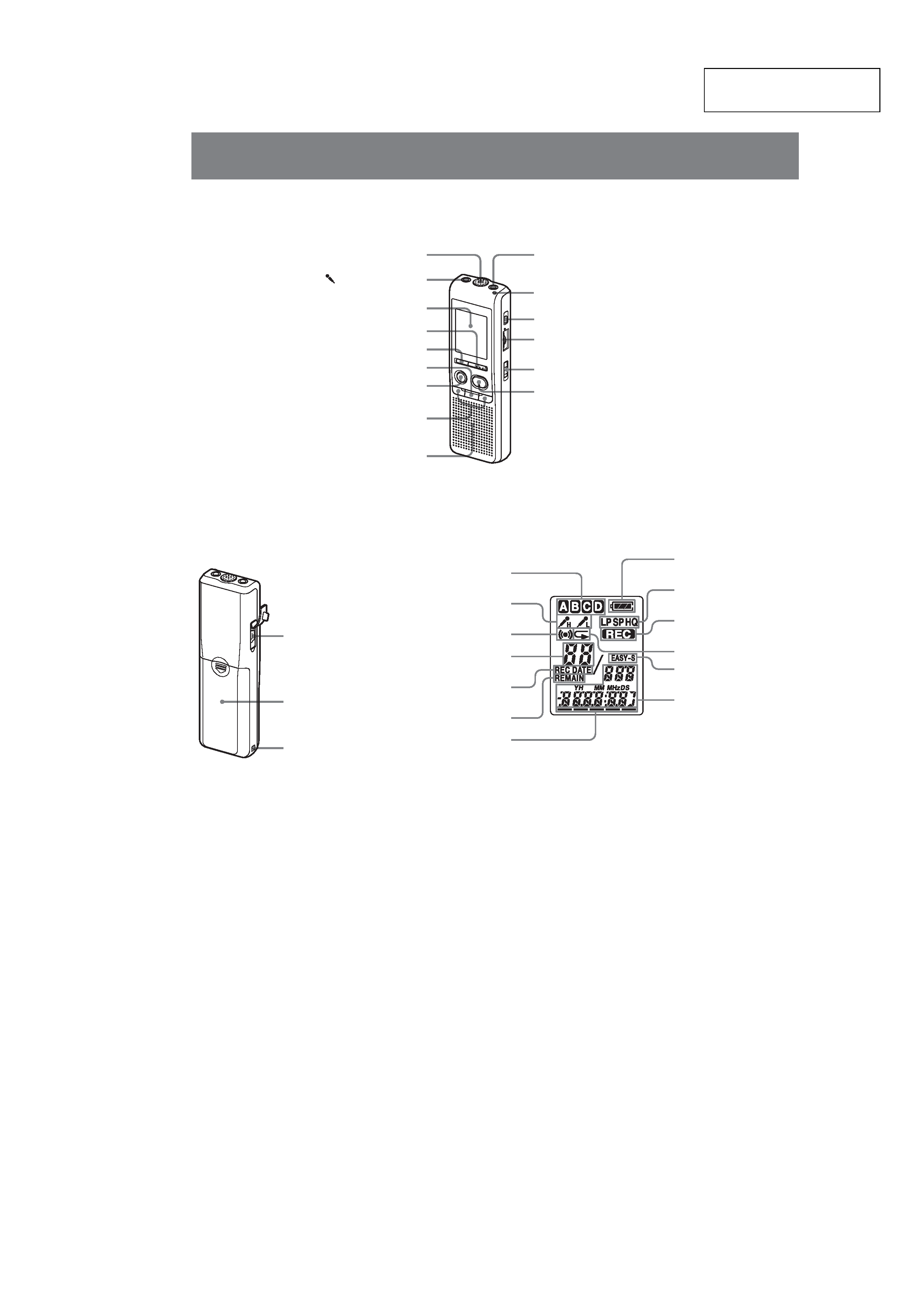
Index to Parts and Controls
Main unit
* There is a tactile dot beside the control to show the
direction to turn up the volume.
** The button has a tactile dot.
MIC (built-in microphone)
(microphone) jack
Display window
DISPLAY/MENU
DIVIDE
xSTOP
zXREC (record) /PAUSE
.(review/fast backward) /
>+ (cue/fast forward) (SELECT)
Speaker
OPR (operation) indicator
ERASE
VOL (volume) control*
HOLD
NxPLAY/STOP (ENTER)**
i (earphone) jack
Rear
Battery
compartment
Hook for handstrap
(not supplied)
USB connector
Display window
Folder indication
Remaining battery
indicator
Microphone sensitivity
Alarm indicator
Selected message number
REC DATE (recorded date)
indication
REMAIN indicator
Remaining memory
indicator
Recording mode
indication
REC (recording)
indicator
Repeat play indicator
Number of messages in
a folder/Menu
indication/Counter /
Remaining time
indication /Recording
date indication /Current
time indication /
Messages
EASY-S (Easy Search)
indicator
4
ICD-P320
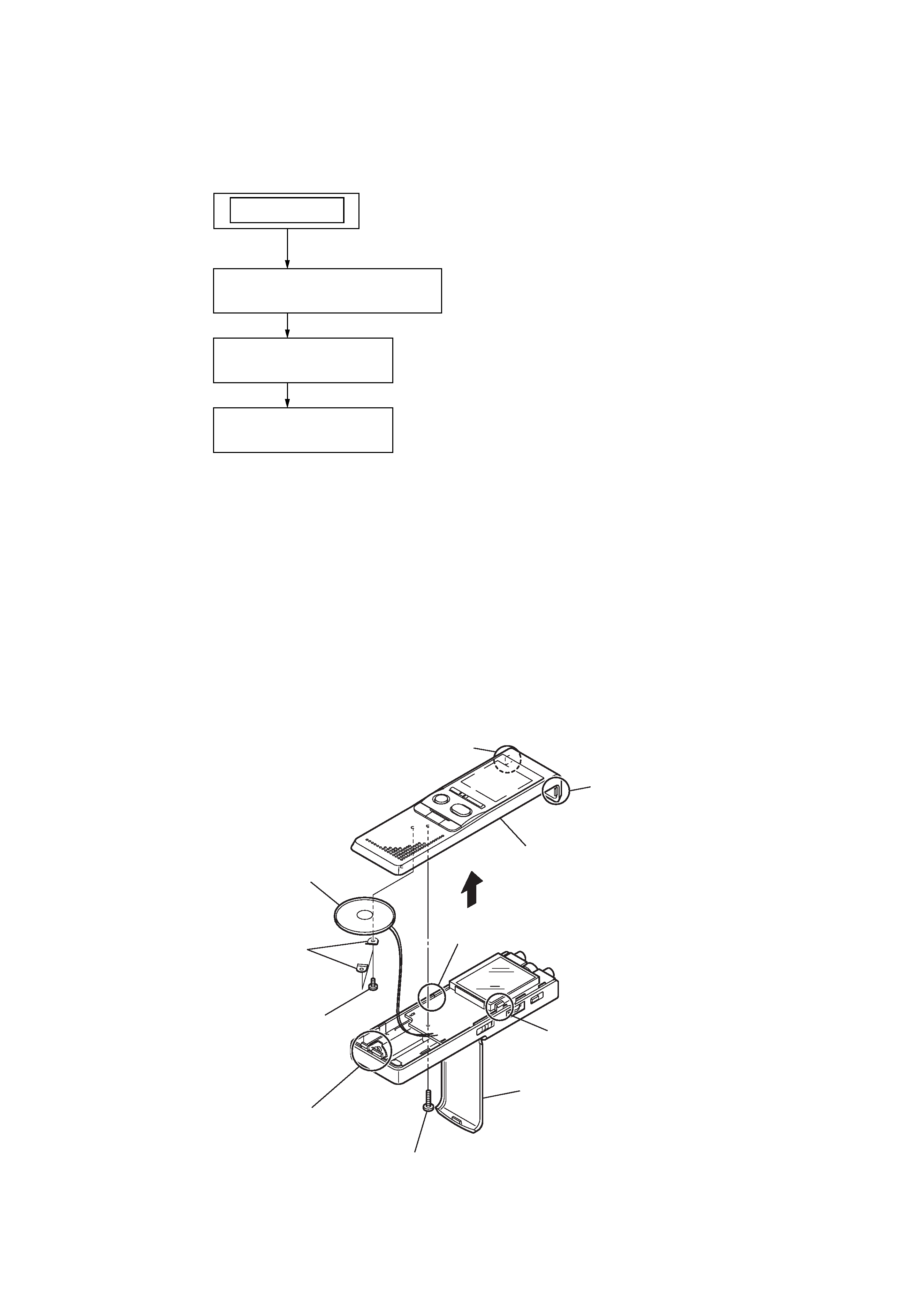
Note : Follow the disassembly procedure in the numerical order given.
2-1. CASE (FRONT) ASSY
SECTION 2
DISASSEMBLY
Note : Disassemble the unit in the order as shown below.
2-1.
CASE (FRONT) ASSY
(Page 4)
2-2.
MAIN BOARD
(Page 5)
SET
2-3.
USB BOARD
(Page 5)
8
2
screw
9
two screws
0
two brackets (speaker)
qa
speaker
qs
case (front) assy
3
claw
4
claw
6
claw
7
claw
5
two claws
1
battery case lid
5
ICD-P320
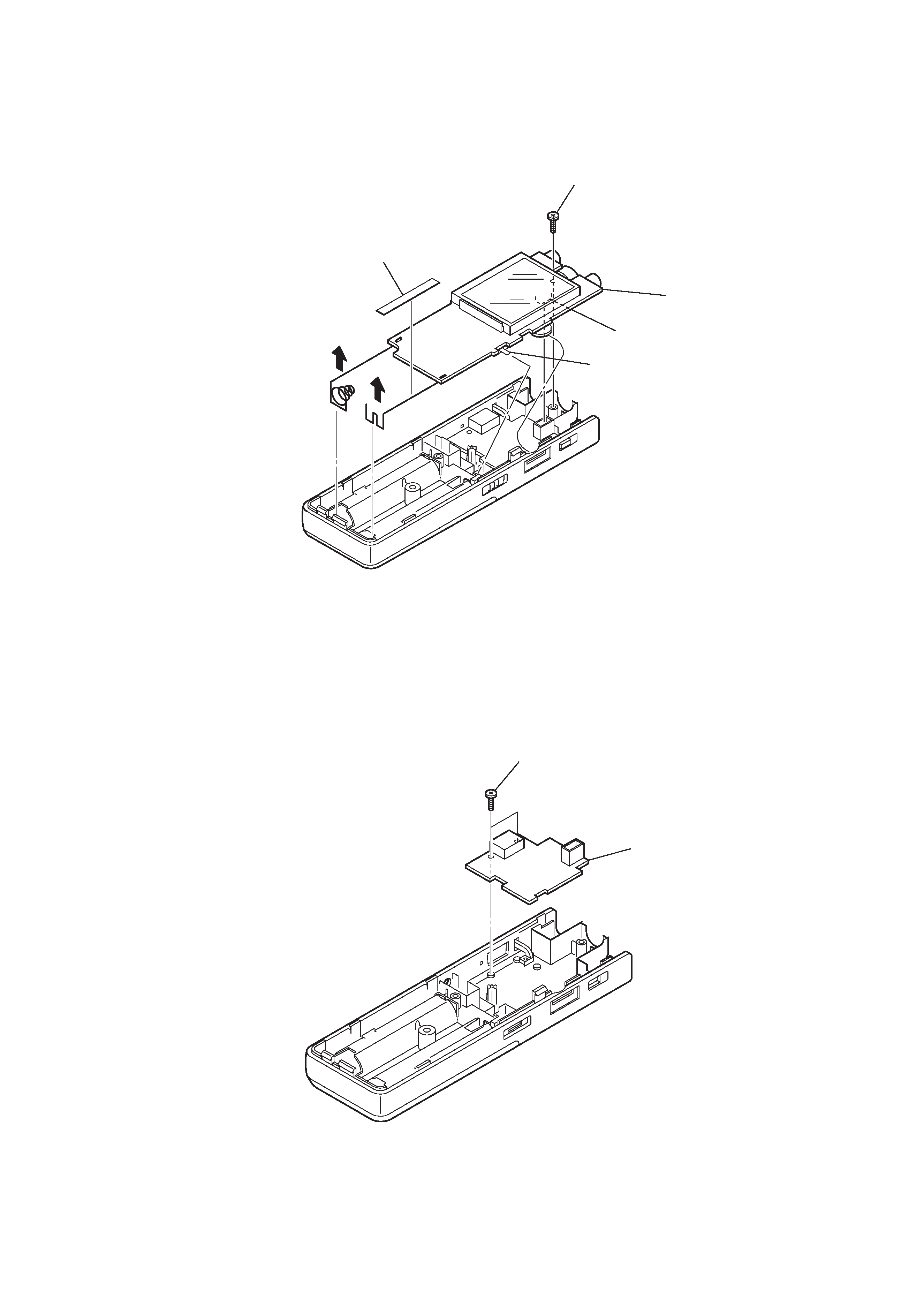
2-2. MAIN BOARD
2-3. USB BOARD
2
USB board
1
two screws
3
4
5
MAIN board
S701
CN2001
1
insulating sheet
2
screw