1
SERVICE MANUAL
US Model
ICD-BM1/BM1PRO
IC RECORDER
SPECIFICATIONS
Ver 1.0 2003. 11
Sony Corporation
Personal Audio Company
Published by Sony Engineering Corporation
9-961-405-01
2003K04-1
© 2003. 11
Recording media
"Memory Stick", Monaural recording
Recording time
Maximum recording time and number of messages for a "Memory Stick"
The maximum recording time for all the folders and the maximum number
of messages are as follows. You can record messages for the maximum
recording time in a single folder.
4MB
8MB
16MB
32MB
64MB
128MB
ST*
10min.
20min.
40min.
1hr 25min. 2hr 50min. 5hr 50min.
SP**
30min.
1hr
2hr 10min. 4hr 20min. 8hr 50min. 17hr 45min.
LP***
1hr 20min. 2hr 50min. 5hr 45min. 11hr 45min. 23hr 35min. 47hr 25min.
Number
456
950
963
1,016
1,016
1,016
of Messages
*ST:
High quality recording mode
(hr: hours /min.: minutes)
(stereo sound with an external stereo microphone not supplied)
**SP: Standard play recording mode (monaural sound)
***LP: Long play recording mode (monaural sound)
Frequency range
ST: 60 Hz - 13,500 Hz
SP: 60 Hz - 7,000 Hz
LP: 80 Hz - 3,500 Hz
Speaker
approx. 28 mm (29/32 in.) dia.
Power output
350 mW
Input/Output
· Earphone jack (minijack) for 8 - 300 ohms ear
receiver/headphones
· Microphone jack (minijack, stereo)
Plug in power
Minimum input level: 0.7 mV 3 kilohms or lower
impedance microphone
· USB connector
· DC IN 3V jack
Playback speed control
+100% to -50% (DPC)
Power requirements
Two size AAA (LR03) alkaline batteries: 3 V DC
Dimensions
36.6
× 112.3 × 21mm (1 1/2 × 4 1/2 × 27/32 in.)
(w/h/d) (not incl. projecting parts and controls)
Mass
98 g (3.5 oz) (incl. batteries and a "Memory Stick")
Supplied accessories
"Memory Stick" (ICD-BM1: 16MB
× 1/
ICD-BM1PRO: 16MB
× 3)
"Digital Voice Editor" (CD-ROM)
× 1
Ear receiver
× 1
USB connecting cable
× 1
Carrying case
× 1
Design and specifications are subject to change without notice.
2
TABLE OF CONTENTS
1. GENERAL
Index to Parts and Controls ..................................................... 3
Getting Started ......................................................................... 3
Basic Operations ...................................................................... 5
Editing Messages ..................................................................... 8
Formatting a "Memory Stick" ................................................. 9
2. DISASSEMBLY
2-1. Knob (Rear) ....................................................................... 10
2-2. Chassis Block Assy ........................................................... 11
2-3. SW Board .......................................................................... 11
2-4. Plate (MS) Section ............................................................ 12
2-5. LCD Board ........................................................................ 12
2-6. Chassis Section ................................................................. 13
2-7. Memory Stick Connector .................................................. 13
2-8. Main Board ....................................................................... 14
3. DIAGRAMS
3-1. IC Pin Descriptions ........................................................... 15
3-2. Block Diagram Main Section ...................................... 21
3-3. Block Diagram LCD/SW Section ............................... 22
3-4. Printed Wiring Board Main Section ............................ 24
3-5. Schematic Diagram Main Section (1/3) ...................... 25
3-6. Schematic Diagram Main Section (2/3) ...................... 26
3-7. Schematic Diagram Main Section (3/3) ...................... 27
3-8. Schematic Diagram LCD/SW Section ........................ 28
3-9. Printed Wiring Board LCD Section ............................ 29
3-10. Printed Wiring Board SW Section .............................. 30
3-11. IC Block Diagrams ............................................................ 31
4. EXPLODED VIEWS
4-1. Main Section ..................................................................... 34
4-2. Case Section ...................................................................... 35
4-3. Ornament Section .............................................................. 36
4-4. Chassis (1) Section ............................................................ 37
4-5. Chassis (2) Section ............................................................ 38
5. ELECTRICAL PARTS LIST ......................................... 39
SAFETY-RELATED COMPONENT WARNING!!
COMPONENTS IDENTIFIED BY MARK 0 OR DOTTED LINE
WITH MARK 0 ON THE SCHEMATIC DIAGRAMS AND IN
THE PARTS LIST ARE CRITICAL TO SAFE OPERATION.
REPLACE THESE COMPONENTS WITH SONY PARTS WHOSE
PART NUMBERS APPEAR AS SHOWN IN THIS MANUAL OR
IN SUPPLEMENTS PUBLISHED BY SONY.
Notes on Chip Component Replacement
· Never reuse a disconnected chip component.
· Notice that the minus side of a tantalum capacitor may be dam-
aged by heat.
ICD-BM1/BM1PRO
· UNLEADED SOLDER
Boards requiring use of unleaded solder are printed with the lead-
free mark (LF) indicating the solder contains no lead.
(Caution: Some printed circuit boards may not come printed with
the lead free mark due to their particular size.)
: LEAD FREE MARK
Unleaded solder has the following characteristics.
· Unleaded solder melts at a temperature about 40°C higher than
ordinary solder.
Ordinary soldering irons can be used but the iron tip has to be
applied to the solder joint for a slightly longer time.
Soldering irons using a temperature regulator should be set to
about 350°C.
Caution: The printed pattern (copper foil) may peel away if
the heated tip is applied for too long, so be careful!
· Strong viscosity
Unleaded solder is more viscous (sticky, less prone to flow)
than ordinary solder so use caution not to let solder bridges
occur such as on IC pins, etc.
· Usable with ordinary solder
It is best to use only unleaded solder but unleaded solder may
also be added to ordinary solder.
Flexible Circuit Board Repairing
· Keep the temperature of the soldering iron around 270°C during
repairing.
· Do not touch the soldering iron on the same conductor of the
circuit board (within 3 times).
· Be careful not to apply force on the conductor when soldering
or unsoldering.
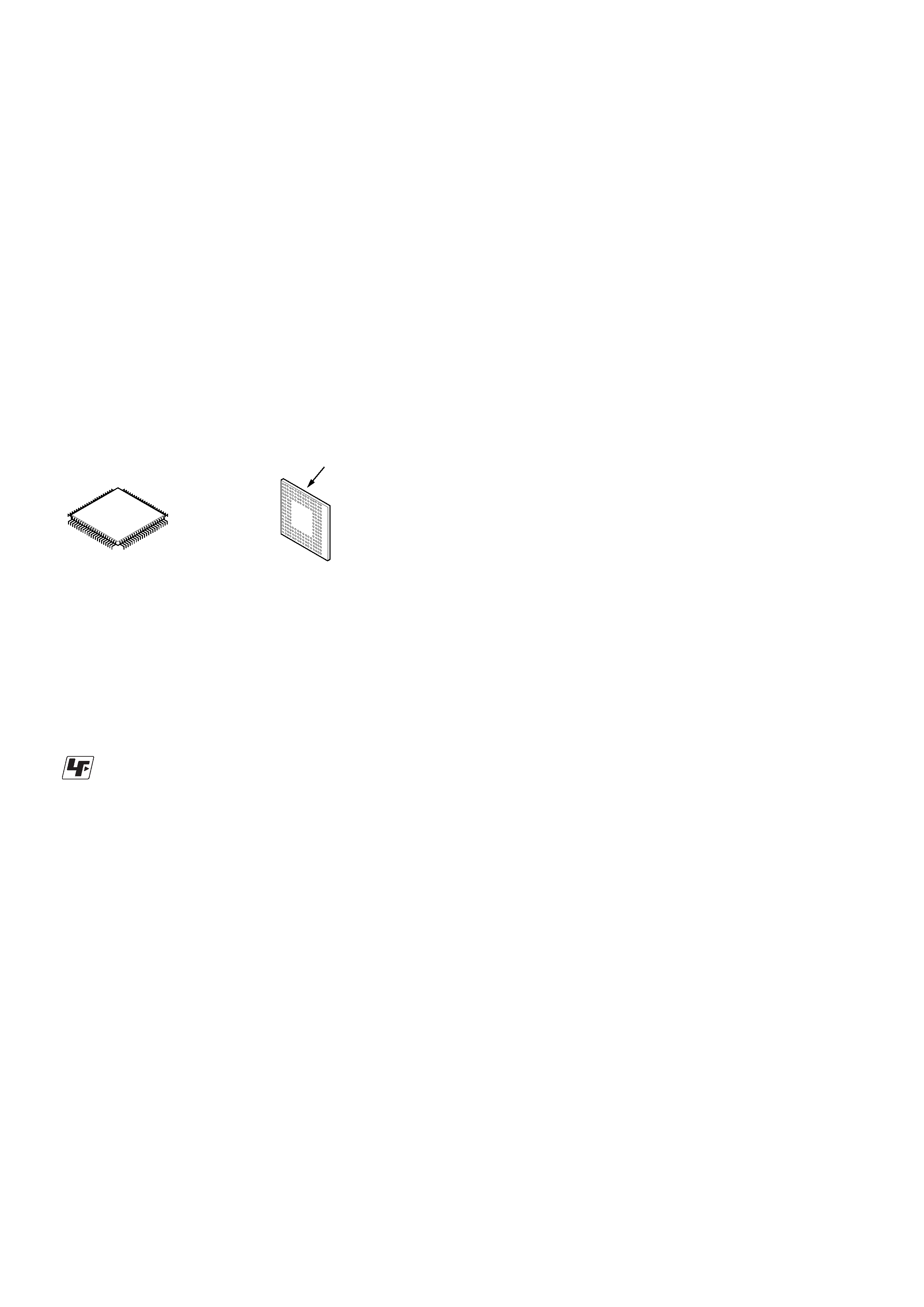
* Replacement of IC601, IC702 used in this set requires a special
tool.
· The voltage and waveform of CSP (chip size package) cannot
be measured, because its lead layout is different from that of
conventional IC.
· Lead layouts
Lead layout of
conventional IC
surface
CSP (chip size package)
3
ICD-BM1/BM1PRO
SECTION 1
GENERAL
This section is extracted
from instruction manual.
64GB
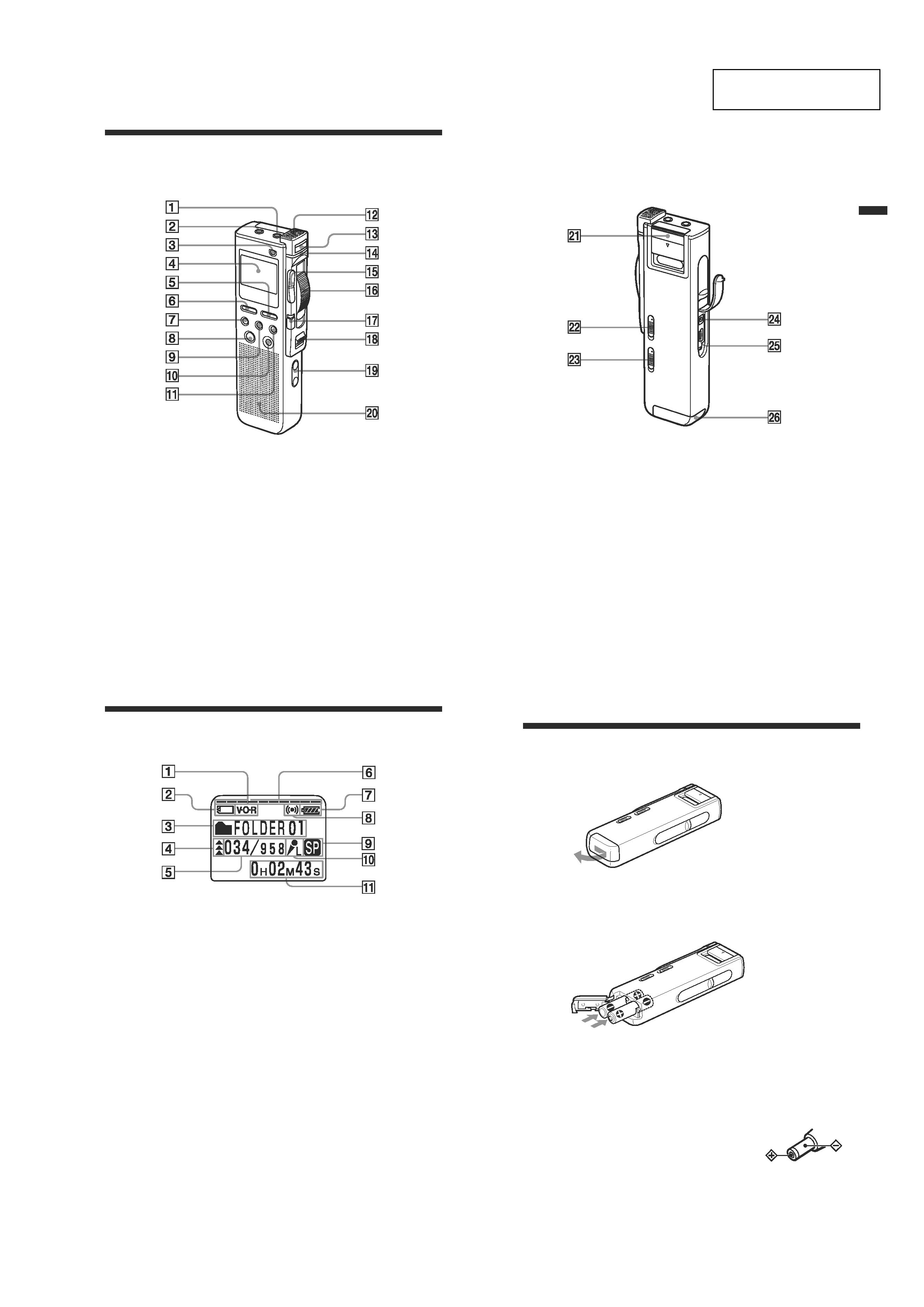
1
MIC (microphone) (PLUG
IN POWER) jack (18)
2 i
(headphones) jack (16, 19,
21)
3
ERASE button (29, 34)
4
Display window (24)
5
MENU button (49)
6
DISPLAY button (26)
7
FOLDER button (13, 20)
8
ENTER button
9
DIVIDE button
0
CANCEL button
qz
PRIORITY button (36)
Index to Parts and Controls
qs
Built-in microphone (14)
qd
NEW FILE button (15)
qf
OPR (operation) indicator
(14, 21)
qg
Jog lever . (review/fast
backward)/> (cue/fast
forward)
qh
Control key REC (record) /
STOP/PLAY/B.SPACE
qj
DPC switch (22, 39)
qk
POWER ON/OFF switch (8,
13)
ql
VOL (volume) +/ buttons
(21)
w;
Speaker
Refer to the pages indicated in parentheses for details.
Front
Ad
ditional
Inf
ormation
65GB
Rear
wz
Memory Stick slot cover (10)
ws
MIC SENS (microphone
sensitivity) switch (17)
CONF(H) (conference,
high)/DICT(L) (dictation,
low)
wd
VOR (voice operated
recording) ON/OFF switch
(16)
wf
DC IN 3V jack (6)
wg
USB connector (52)
wh
Battery compartment (6)
24GB
Using the Display Window
Parts in the display window
1
VOR (voice operated
recording) indicator (16)
2
"Memory Stick" indicator
3
Folder indication (13, 20)
Displays the current folder.
4
Priority marks (36)
5
Selected message number /
Total message number in the
folder (14, 20)
6
Remaining memory
indicator (17)
7
Remaining battery indicator (7)
When the AC power adaptor
(not supplied) is connected,
the indicator does not appear.
8
Alarm indicator (45)
Appears when the alarm is
set for a message.
9
Recording mode indication (50)
·ST: High quality recording
mode (stereo sound with an
external stereo microphone
not supplied)
· SP: Standard play recording
mode (monaural sound)
· LP: Long play recording
mode (monaural sound)
0
Microphone sensitivity
indication (17)
Displays the current
microphone sensitivity
setting with the MIC SENS
(microphone sensitivity)
switch:
· H (high): CONF(H)
position is selected to
record at a meeting or in a
quiet/spacious place.
· L (low): DICT(L) position
is selected to record for
dictation.
qa
Counter /Remaining time
indication /Recording date
and time indication /
Message name indication/
Current time indication (26,
27)
The display selected with the
DISPLAY button appears.
Note
The effect of the back light of the
display window may be reduced
in a bright location.
6GB
B
Getting Started
Step 1: Installing the Batteries
1 Slide and lift the battery compartment lid.
2 Insert two LR03 (size AAA) alkaline batteries with correct
polarity, and close the lid.
Clock setting display appears when you insert batteries for the first time or
after the unit has been without batteries for a certain period of time. Please
refer to steps 3 to 6 in "Step 2: Setting the Clock" on pages 8 and 9 to set
the date and time.
Using on house current
Connect the AC power adaptor AC-E30HG (not
supplied) to the DC IN 3V jack of the unit and to
the wall outlet. Do not use any other AC power
adaptor.
Polarity of the plug
4
ICD-BM1/BM1PRO
7GB
Getting
Star
ted
Replacing the Batteries
The battery indicator on the display window shows the battery condition.
Notes
· Do not use manganese batteries for this unit.
·When you replace the batteries, insert the new ones within 3 minutes after you
remove the exhausted ones. Otherwise, the display may show the clock setting
or incorrect date and time when you re-insert the batteries. In this case, set the
date and time again. The recorded messages and alarm setting, however, will
remain.
· Do not charge dry batteries.
·When you are not going to use the unit for a long time, remove the batteries to
prevent damage from battery leakage and corrosion.
Battery remain indication
: Replace both of the two batteries with new ones.
m
:
The "LOW BATTERY" is displayed
and the unit will stop operation.
Battery life (Using Sony alkaline batteries LR03 (SG))
(Recording mode:)
ST
SP
LP
In continuous recording:
Approx. 11 hours
Approx. 14 hours
Approx. 16 hours
In continuous playback*:
Approx. 6.5 hours
Approx. 7.5 hours
Approx. 8.5 hours
*When playing back through the internal speaker with the medium volume
level
* The battery life may shorten depending on the operation of the unit.
8GB
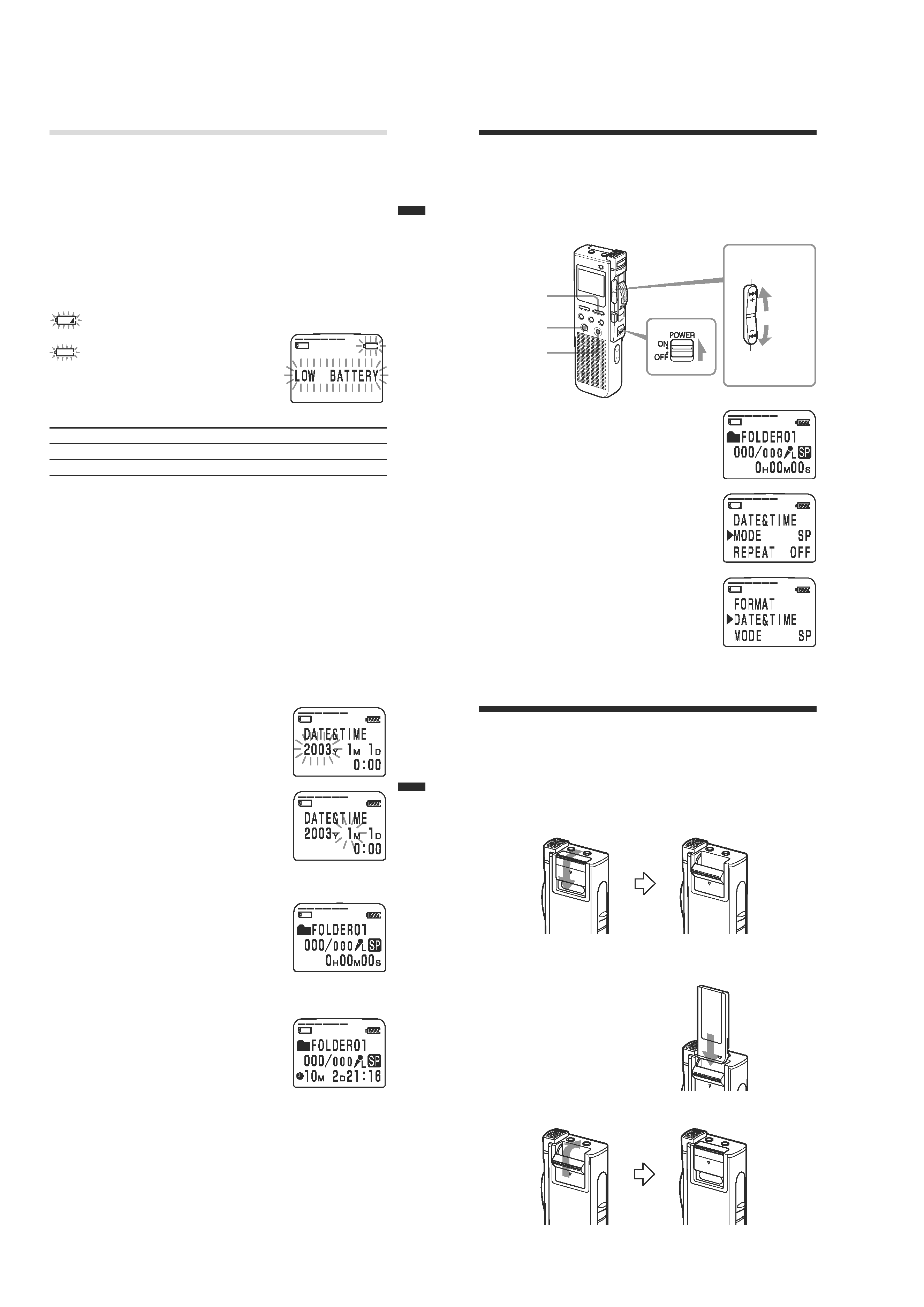
Jog lever
Step 2: Setting the Clock
You need to set the clock to use the alarm function or record the date and
time.
Clock setting display appears when you insert battery for the first time, or
when you insert battery after the unit has been without battery for a
certain period of time. In this case, proceed from step 4.
1 Slide POWER to ON.
The IC recorder is turned on.
2 Press MENU.
The menu mode will be displayed in the
display window.
3 Press the jog lever up or down (>/
.
) to select "DATE&TIME".
Press up (>).
Press down (.).
POWER
MENU
ENTER
CANCEL
9GB
Getting
Star
ted
4 Press ENTER.
The date and time setting window is
displayed. The year digits will flash.
5 Set the date and time.
1
Pressthe jog lever up or down (>/
.
) to selectthe digits of the year.
2
PressENTER.
The month digit will flash.
3
Setthe month, day, and the time in
sequence,then press ENTER.
The menu mode will be displayed again.
6 Press MENU.
The window will return to the normal display.
To cancel the operation
PressCANCEL to return to the previous step of the operations.
To display the current time
Press ENTER while the unit is in the stop mode
(page 27).
The current time will be displayed for three
seconds.
Note
When no "Memory Stick" is inserted or the power is
turned off, the current time will not be displayed.
10GB
Step 3: Inserting a "Memory Stick" into
the IC Recorder
Notes
· Make sure to insert or remove the "Memory Stick" while the unit is turned off.
·Never remove the "Memory Stick" while the unit is accessingthe "Memory
Stick". (The OPR indicator flashes in orange.)
1 Slide and open the "Memory Stick" slot cover.
2 Insert a "Memory Stick" into the "Memory Stick" slot with the
terminal side facing inside the recorder. Insert it firmly until it
clicks into place.
Note
Do not insert a "Memory Stick" in a
different direction. It may cause
malfunction of the unit.
3 Close the "Memory Stick" slot cover.
5
ICD-BM1/BM1PRO
11GB
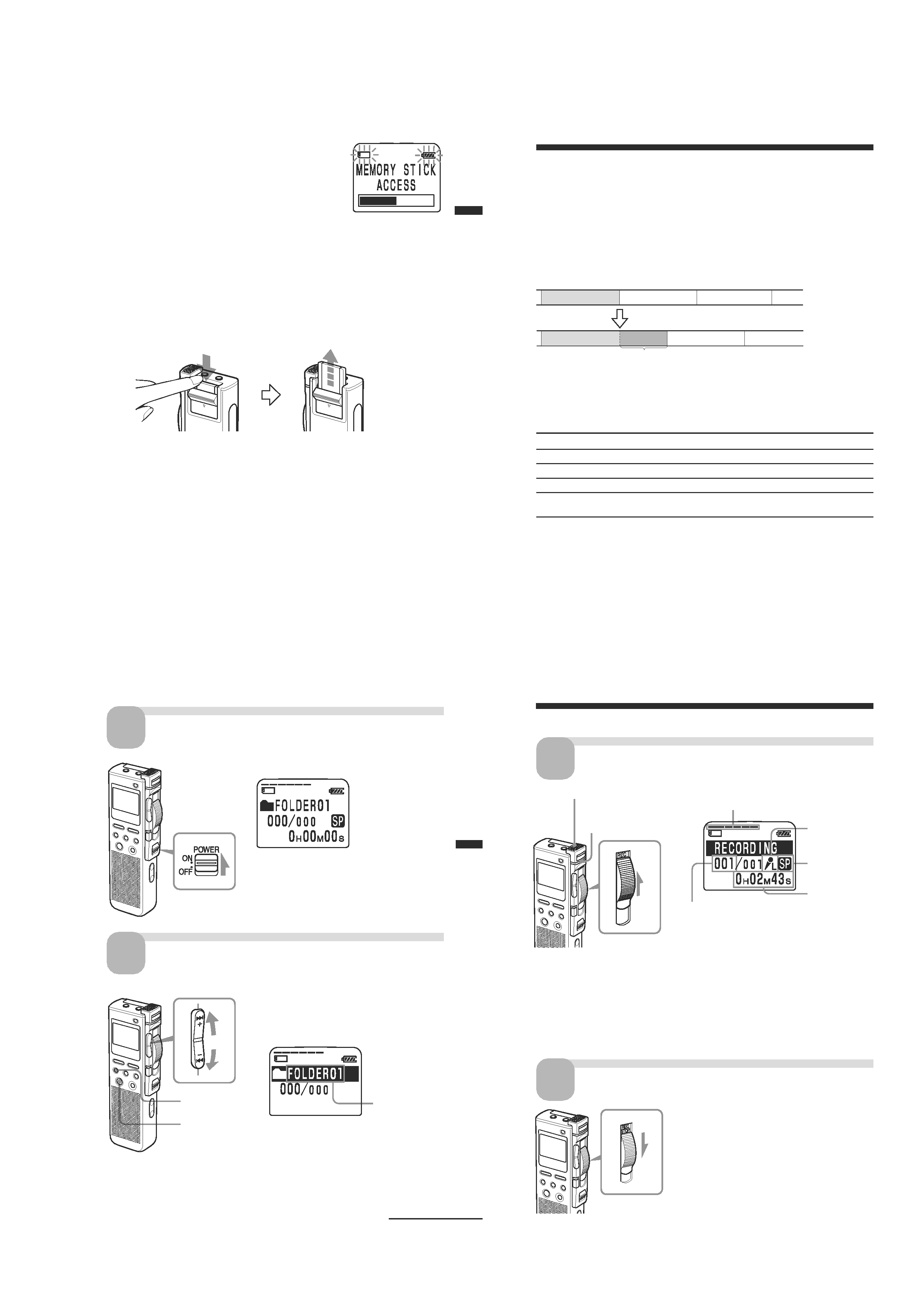
Note on the "ACCESS" message
The unit is accessingdata while "MEMORY STICK
ACCESS" appears in the display window or the
OPR indicator flashes in orange. While accessing,
do not remove the "Memory Stick", batteries, or
the AC adaptor (not supplied). Doing so may
damage the data.
Notes
· The unit starts accessing the data after it is turned on.
· If the unit is required to processexcessiveamount of data, "MEMORY STICK
ACCESS" may be displayed for an extended period of time. This is not a
malfunction of the unit. Wait until the messagedisappears.
Removing the "Memory Stick"
Make sure that "MEMORY STICK ACCESS" disappears, and turn off the
unit. Then open the "Memory Stick" slot cover and push the "Memory
Stick" into the slot, so that the "Memory Stick" pops out.
Remove the "Memory Stick" from the slot as shown below.
The types of "Memory Stick" you can use with this IC
Recorder
You can also use the following "Memory Stick" of a 4 MB to 128MB
capacity instead of the supplied "Memory Stick". The maximum
recording time varies depending on the capacity of the "Memory Stick".
· "Memory Stick"
· "Memory Stick (with memory selectfunction)" (incorporating two
128MB memory units)
· "MagicGate Memory Stick"
· "Memory Stick Duo" (when inserted into the "Memory Stick Duo"
adaptor)
Notes
· The unit does not support the "Memory Stick PRO".
·"MagicGate" is a copyright protection technology that usesan encryption
technology. This unit does not support the MagicGate standard, and therefore,
recorded data using this unit is not subject to the protection of copyrights by
MagicGate.
Getting
Star
ted
12GB
B
Basic Operations
Recording Messages
You can record messages in each (initially named FOLDER01, FOLDER02,
and FOLDER03)folder. The maximum number of recordable messages
differs depending on the "Memory Stick" capacity.
You can record messagesusing the following three functions:
· Add a recording to a previously recorded message(next page)
· Add a recording as a new message(page 15)
· Add an overwrite recording (page 15)
This section explains how to add a recording to a previously recorded message.
Maximum recording time and number of messages for a
"Memory Stick"
The maximum recording time for all the folders and the maximum number
of messagesare as follows. You can record messagesfor the maximum
recording time in a single folder.
4MB
8MB
16MB
32MB
64MB
128MB
ST*
10min.
20min.
40min.
1hr 25min. 2hr 50min.
5hr 50min.
SP**
30min.
1hr
2hr 10min. 4hr 20min. 8hr 50min.
17hr 45min.
LP***
1hr 20min. 2hr 50min. 5hr 45min. 11hr 45min. 23hr 35min. 47hr 25min.
Number
456
950
963
1,016
1,016
1,016
of Messages
*ST:
High quality recording mode
(hr: hours /min.: minutes)
(stereo sound with an external stereo microphone not supplied)
**SP: Standard play recording mode (monaural sound)
***LP: Long play recording mode (monaural sound)
Notes
·For switching the recording mode, see page 50.
· Before making a long recording, be sure to check the battery indicator (page 7).
· The maximum recording time and the number of messagesyou can make vary
depending on the conditions of use.
·To avoid replacing batteries during long recordings, use the AC power
adaptor (not supplied).
Message 1
Message 2
Message 3
Message 1
Message 2
Message 3
Starts recording at the end of Message 1
Added recording (counted as a part of Message1)
Basic
Operations
13GB
Turn on the power.
Slide POWER to ON.
Select the folder.
2
FOLDER
1
POWER
1
Press FOLDER.
2
Press the jog lever up or down (>/
.
) to display the folder in which
you wish to record messages.
ENTER
Selected folder
Continued
3
Press ENTER to select the folder.
To cancel the selection, press CANCEL.
To add a new folder, see page 33.
Jog lever
14GB
Slide the control key to STOP.
The unit stops at the end of the current
recording.
If you do not change the folder after you stop
recording, the next time you record you will
record from the end of the current recording.
The added recording will be counted as part
of the current message.
Stop recording.
4
Start recording.
3
1
Slide the control key to REC.
2
Speak into the built-in microphone.
Remaining memory
Recording
mode
Current message number
Built-in microphone
Microphone
sensitivity
Recording Messages (continued)
OPR indicator
(lights in red during
recording)
Counter
display*
* The display selectedwith the DISPLAY button (page 26) appears.
Notes
· While the OPR indicator flashes or when it turns orange, do not remove the
"Memory Stick", the batteries or the AC adaptor (not supplied). Doing so may
damage the data.
· Noise may be recorded if an object, such as your finger, etc., accidentally rubs
or scratchesthe unit during recording.