MICROFILM
SERVICE MANUAL
FRS TWO-WAY RADIO
US Model
SPECIFICATIONS
ICB-U655
Photo: Yellow model
Ver 1.2
2000. 07
With SUPPLEMENT-1 (9-926-965-81)

2
TABLE OF CONTENTS
1.
SERVICING NOTES ............................................... 3
2.
GENERAL
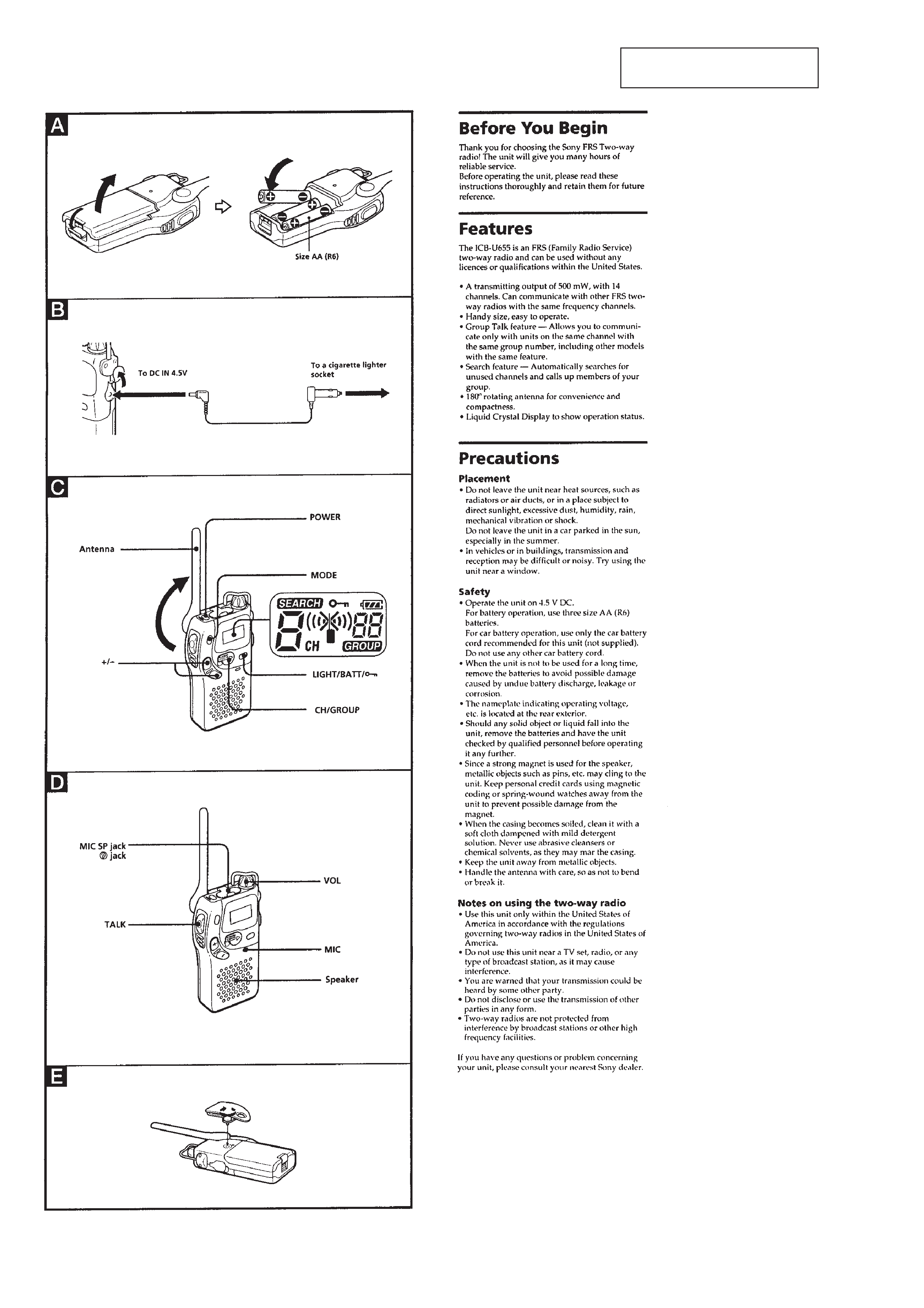
Before You Begin ............................................................
4
Features ...........................................................................
4
Precautions ......................................................................
4
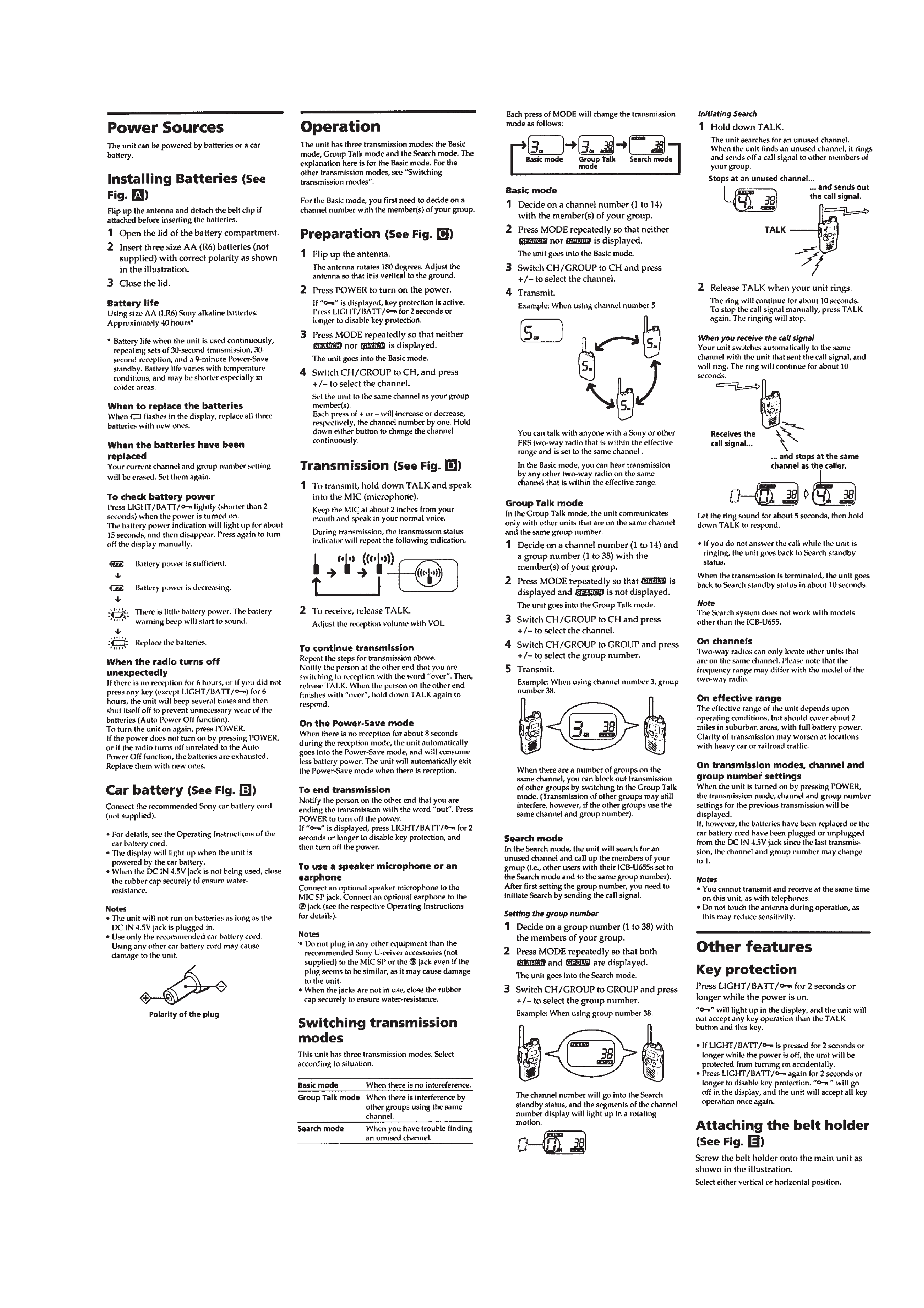
Power Sources .................................................................
5
Operation .........................................................................
5
Other features ..................................................................
5
3.
DISASSEMBLY ......................................................... 6
4.
ELECTRICAL ADJUSTMENTS ......................... 7
5.
DIAGRAMS
5-1. Block Diagram ................................................................
9
5-2. Printed Wiring Boards .................................................... 12
5-3. Schematic Diagram ......................................................... 15
5-4. IC Pin Function Description ........................................... 22
6.
EXPLODED VIEWS ................................................ 24
7.
ELECTRICAL PARTS LIST ............................... 26
Flexible Circuit Board Repairing
· Keep the temperature of the soldering iron around 270 °C dur-
ing repairing.
· Do not touch the soldering iron on the same conductor of the
circuit board (within 3 times).
· Be careful not to apply force on the conductor when soldering
or unsoldering.
Notes on chip component replacement
· Never reuse a disconnected chip component.
· Notice that the minus side of a tantalum capacitor may be dam-
aged by heat.
3
SECTION 1
SERVICING NOTES
About special screws
Special screws are used for this machine not to be remodeled the
inside by any users. Therefore, repair should be done with the driver
described below.
7-721-052-08
special driver
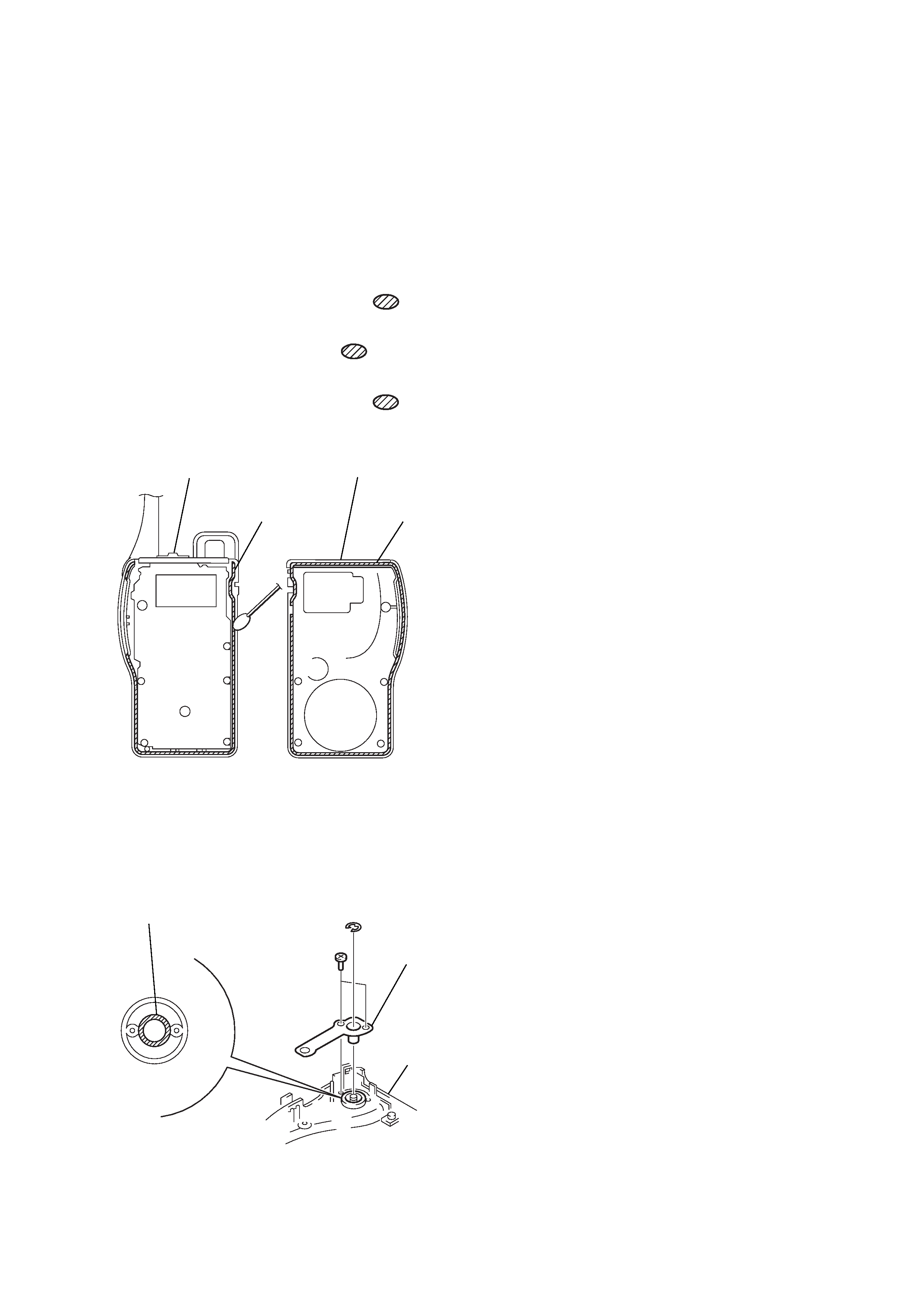
Drip-proof treatment
Always perform the following treatment when the Cabinet was
removed, or the Contact Board (ANT) Assembly was removed
during repair.
1. Apply SONY Grease SGL-505 (7-662-010-04) to entire sur-
face of Cabinet Rear Assembly marked with
using a swab.
(See Fig. A)
2. Apply Sealant TSE-392W (7-432-950-03) to entire surface of
Cabinet Rear Assembly marked with
using a swab. (See
Fig. A)
3. Apply SONY Grease SGL-505 (7-662-010-04) to entire sur-
face of Cabinet Rear Assembly marked with
using a swab.
(See Fig. B)
cabinet (front) assy
cabinet (rear) assy
Apply grease
(SGL-505).
Apply grease
(SGL-505).
contact plate
(ANT) assy
cabinet (rear)
assy
Apply sealant
(TSE-392W).
(FIg. A)
(FIg. B)
4
SECTION 2
GENERAL
This section is extracted from
instruction manual.
5