HTC-WX5
E Model
Australian Model
Tourist Model
SERVICE MANUAL
COMPACT DISC DECK
SPECIFICATIONS
HTC-WX5 is the deck and CD
section in MHC-WX5/WX7.
CD
SECTION
TAPE DECK
SECTION
Model Name Using Similar Mechanism
HTC-W555
CD Mechanism Type
CDM38-5BD29A
Base Unit Type
BU-5BD29AL
Optical Pick-up Type
KSS-213B/S-N
Model Name Using Similar Mechanism
HCD-VR90AV
Tape Transport Mechanism Type
TCM-230AWR2
9-928-993-12
2003E16-1
© 2003.05
Sony Corporation
Home Audio Company
Published by Sony Engineering Corporation
CD player section
System
Compact disc and digital audio system
Laser
Semiconductor laser ( =780nm)
Emission duration : continuous
Laser output
Max. 44.6 µW*
*This output is the value measured at a
distance of 200mm from the objective
lens surface on the Optical Pick-up Block
with 7mm aperture.
Frequency response
20Hz 20kHz (±1dB)
Wavelength
780 790 nm
Signal-to-noise ratio
More than 90dB
Dynamic range
More than 90dB
CD OPTICAL DIGITAL OUT
(Square optical connector jack, rear panel)
Wavelength
600nm
Output Level
-18dBm
Tape player section
Recording system
4-track 2-channel stereo
Frequency response
40 13,000Hz (±3dB), using Sony TYPE I
(DOLBY NR OFF)
cassette 40 14,000Hz (±3dB), using Sony
TYPE II cassette
General
Dimensions (w/h/d)
Approx. 288
× 205 × 360mm
Mass
Approx. 4.4kg
Design and specifications are subject to change without notice.
Ver 1.1 2003. 05
2
CAUTION
Use of controls or adjustments or performance of procedures
other than those specified herein may result in hazardous
radiation exposure.
Notes on chip component replacement
· Never reuse a disconnected chip component.
· Notice that the minus side of a tantalum capacitor may be
damaged by heat.
Flexible Circuit Board Repairing
· Keep the temperature of soldering iron around 270°C
during repairing.
· Do not touch the soldering iron on the same conductor of the
circuit board (within 3 times).
· Be careful not to apply force on the conductor when soldering
or unsoldering.
Laser component in this product is capable of emitting radiation
exceeding the limit for Class 1.
This appliance is classified as
a CLASS 1 LASER product.
The
CLASS
1
LASER
PRODUCT MARKING is
located on the rear exterior.
NOTES ON HANDLING THE OPTICAL PICK-UP BLOCK
OR BASE UNIT
The laser diode in the optical pick-up block may suffer electrostatic
break-down because of the potential difference generated by the
charged electrostatic load, etc. on clothing and the human body.
During repair, pay attention to electrostatic break-down and also
use the procedure in the printed matter which is included in the
repair parts.
The flexible board is easily damaged and should be handled with
care.
NOTES ON LASER DIODE EMISSION CHECK
The laser beam on this model is concentrated so as to be focused on
the disc reflective surface by the objective lens in the optical pick-
up block. Therefore, when checking the laser diode emission,
observe from more than 30 cm away from the objective lens.
LASER DIODE AND FOCUS SEARCH OPERATION
CHECK
Carry out the "S curve check" in "CD section adjustment" and check
that the S curve waveform is output three times.
SAFETY-RELATED COMPONENT WARNING!!
COMPONENTS IDENTIFIED BY MARK
! OR DOTTED LINE WITH
MARK
! ON THE SCHEMATIC DIAGRAMS AND IN THE PARTS
LIST ARE CRITICAL TO SAFE OPERATION. REPLACE THESE
COMPONENTS WITH SONY PARTS WHOSE PART NUMBERS
APPEAR AS SHOWN IN THIS MANUAL OR IN SUPPLEMENTS
PUBLISHED BY SONY.

3
TABLE OF CONTENTS
1. SERVICING NOTE .......................................................... 4
2. GENERAL .......................................................................... 7
3. DISASSEMBLY
3-1. Loading Panel ................................................................. 8
3-2. Back Panel and CD Mechanism Deck ............................ 8
3-3. Front Panel ...................................................................... 9
3-4. TC Mechanism Deck and Cassette Holder ..................... 9
3-5. Disc Tray ....................................................................... 10
4. MECHANICAL ADJUSTMENTS .......................... 11
5. ELECTRICAL ADJUSTMENTS ............................... 11
6. DIAGRAMS
6-1. Circuit Boards Location ................................................ 14
6-2. Block Diagrams
· CD Section ....................................................................... 15
· Deck Section .................................................................... 16
· Main Section .................................................................... 14
6-3. Printed Wiring Board CD Section .............................. 18
6-4. Schematic Diagram
CD Section ................................ 19
6-5. Schematic Diagram Deck Section .............................. 20
6-6. Printed Wiring Board Deck Section ............................ 21
6-7. Printed Wiring Board Main Section ............................ 22
6-8. Schematic Diagram Main (1/2) Section ...................... 23
6-9. Schematic Diagram Main (2/2) Section ...................... 24
6-10. Printed Wiring Board Leaf SW Section .................... 25
6-11. Schematic Diagram Leaf SW Section ...................... 25
6-12. Printed Wiring Board Panel Section ......................... 26
6-13. Schematic Diagram Panel Section ............................ 27
6-14. Schematic Diagram CD Motor Section .................... 28
6-15. Printed Wiring Board CD Motor Section ................. 29
6-16. IC Block Diagrams ..................................................... 30
6-17. IC Pin Functions ......................................................... 32
7. EXPLODED VIEWS
7-1. Case and Back Panel Section ........................................ 39
7-2. Front Panel Section ....................................................... 40
7-3. CD Mechanism Section 1 (CDM38-5BD29A) ............. 41
7-4. CD Mechanism Section 2 (CDM38-5BD29A) ............. 42
7-5. Base Unit Section (BU-5BD29A) ................................. 43
7-6. TC Mechanism Section 1 (TCM230AWR2) ................ 44
7-8. TC Mechanism Section 2 (TCM230AWR2) ............... 45
8. ELECTRICAL PARTS LIST ........................................ 46
4
SECTION 1
SERVICING NOTE
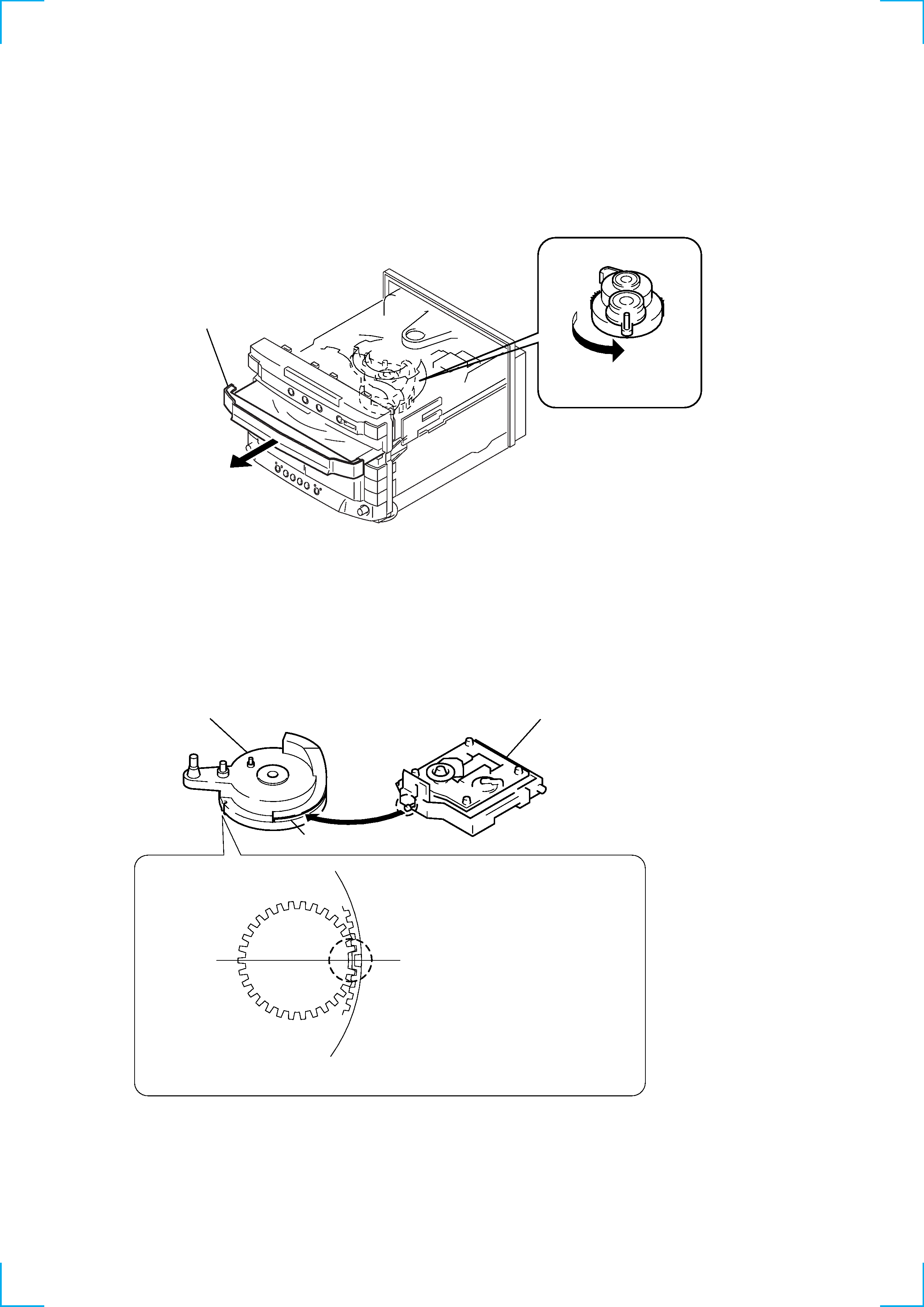
HOW TO OPEN THE DISC TRAY WHEN POWER SWITCH
TURNS OFF
1
Remove the Case.
Note for Installation (ROTARY ENCODER)
3
Pull-out the disc tray.
2
Turn the cam to the
direction of arrow.
BU cam
Groove
Section A
Note:When attaching the Base unit, Insert the
section A into the groove of BU cam.
Note:When attaching the BU cam,
engage the Rotary encoder
switch as shown in the figure.
5
CD
> (AMS)
s (TAPE B) button + DISC3 button
. (AMS)
s (TAPE B) button + DISC1 button
M
s (TAPE A) button + DISC3 button
m
s (TAPE A) button + DISC1 button
TAPE A
> (AMS)
DISC SKIP button + H (TAPE B)
TAPE B
. (AMS)
DISC SKIP button + h (TAPE B)
M
DISC SKIP button + H (TAPE A)
m
DISC SKIP button + h (TAPE A)
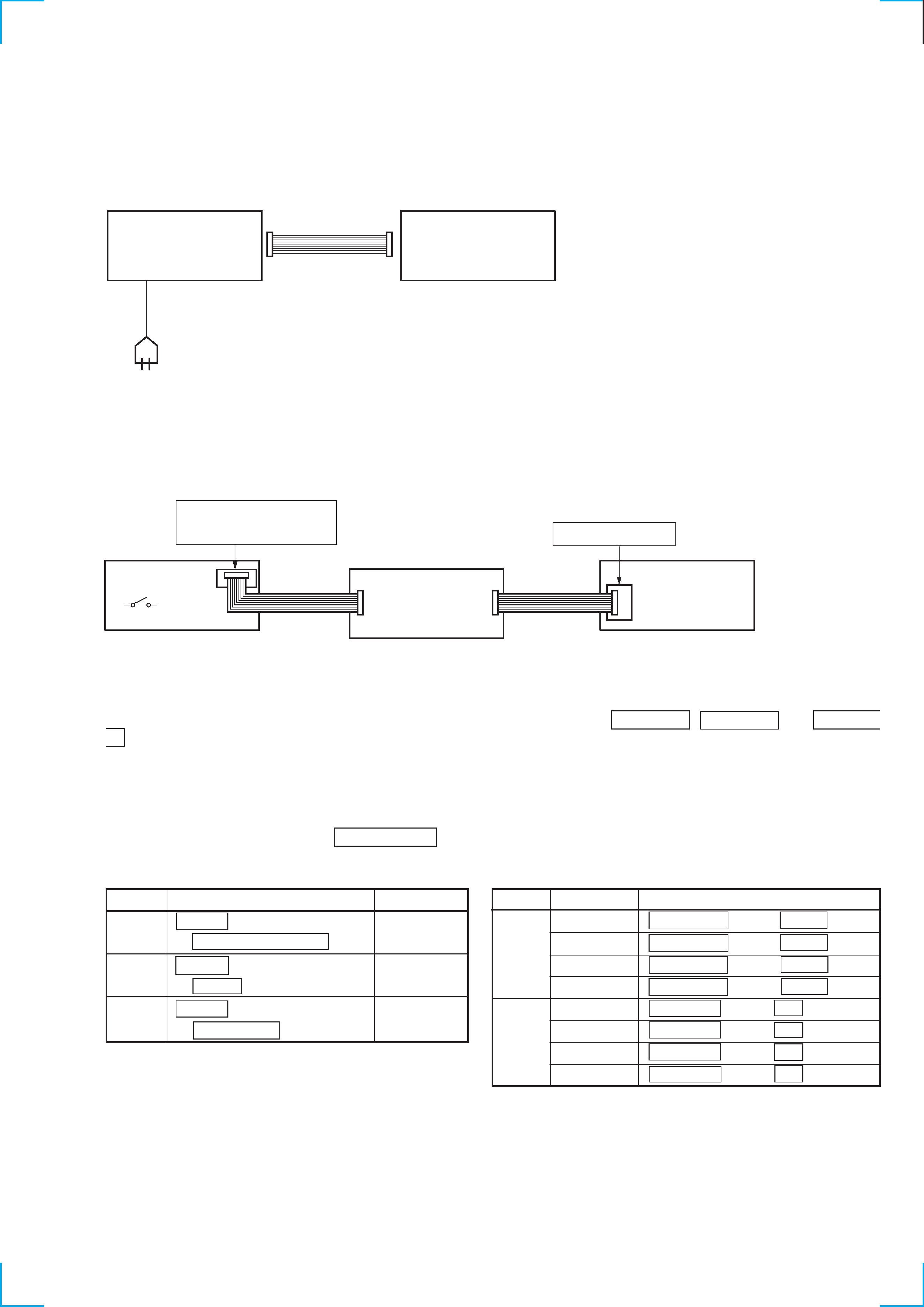
Connection and Operations of the Unit by Itself
This unit cannot be operated by itself as it does not come with a power supply.
Connect STR-WX5/WX7 as shown in "Connection 1" before beginning servicing.
Connection 1: If there is STR-WX5/WX7.
STR-WX5/WX7
SYSTEM CABLE 17P
SET
AC IN
Use a power supply jig (PFJ-1) if the STR-WX5/WX7 is not available.
Connect the conversion jig for connection (J-2501-138-A) as shown in "Connection 2" before beginning servicing.
Connection 2: If there is not STR-WX5/WX7.
Set
Conversion
Jig
(J-2501-138-A)
Power SW
Service Box (PFJ-1)
Connector
cable 17P
(Supplied with PFJ-1)
Connector
cable 17P
(Supplied with
Conversion Jig or Set)
FH-E939,838,737
MHC-6600,5600,3600,2600
CDP/TC
SYSTEM CONTROL
To operate the unit by itself, turn on the power of the conduction jig (PFJ-1), and press the s (TAPE A) , s (TAPE B) , and H (TAPE
B) buttons together in this order.
As this unit is not equipped with fast forward and rewind buttons, buttons need to be combined and pressed together for different functions
when operating the unit by itself. (See Table-2.)
However, it will not operate properly if operations are performed without switching the functions.
Perform the following procedure to switch the functions before operating the unit.
The function selected is indicated by the DISC NUMBER indicator.
Table 1 Switching the Functions
Table 2 Pressing Combination of Buttons When Operated by Itself
Function
CD
x (CD) button
1<
2<
3
+ HI-SPEED DUBBING button
TAPE A
x (CD) button
1<
2
3
+ z REC button
TAPE B
x (CD) button
12<
3
+ h (TAPE A) button
Operation
The function can be differentiated by the lighting of this part of the indicator.
1<
2<
3
Indicator
Deck
Function
Operation