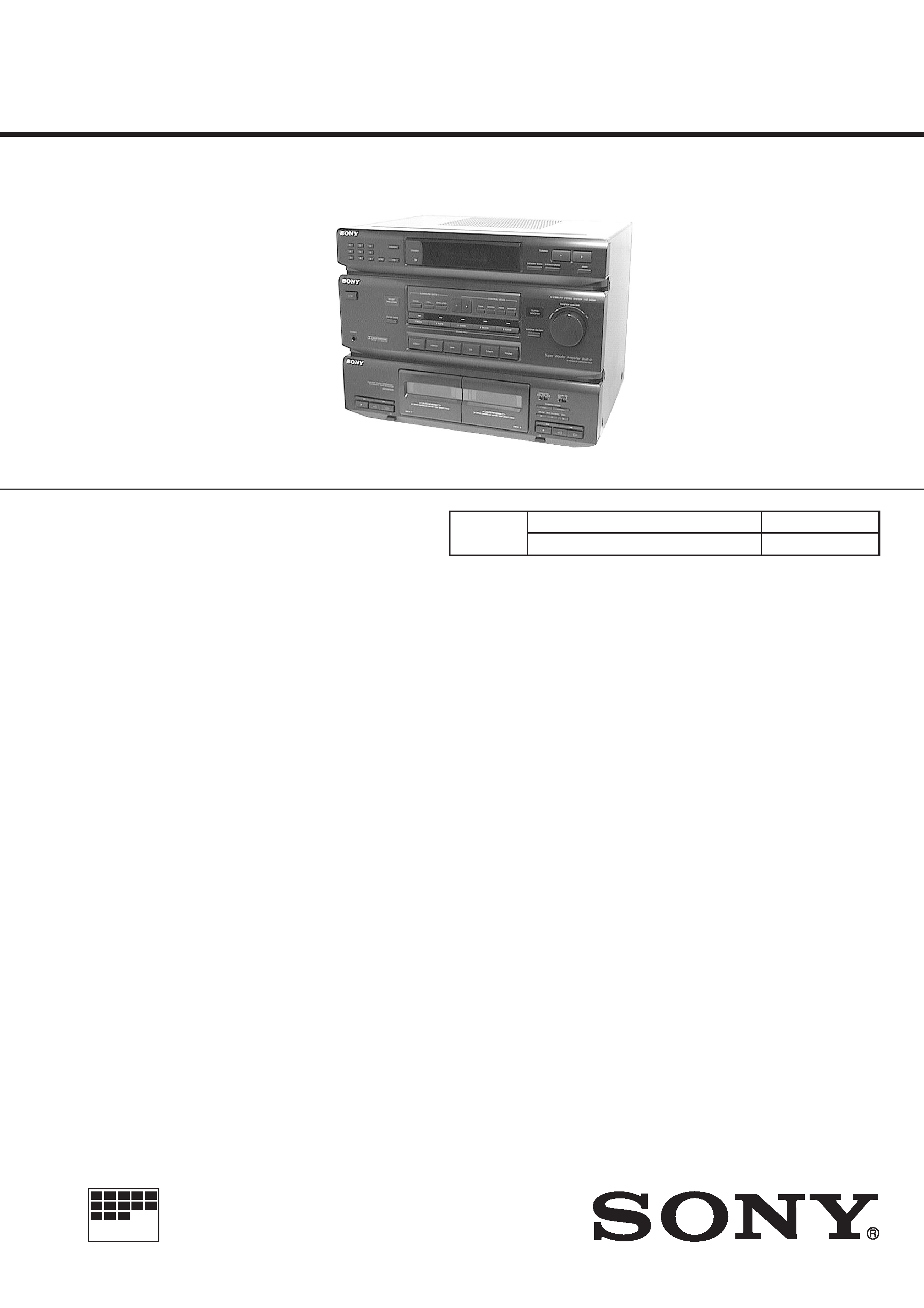
HST-SE581
AEP Model
E Model
Australian Model
SERVICE MANUAL
CASSETTE DECK RECEIVER
MICROFILM
Manufactured under license from Dolby Laboratories
Licensing Corporation.
"DOLBY" and the double-D symbol
a and "PRO
LOGIC" are trademarks of Dolby Laboratories
Licensing Corporation.
· This set is the tuner deck and amplifier
section in SEN-T481.
SPECIFICATIONS
Tape deck
Model Name Using Similar Mechanism
HST-471
Section
Tape Transport Mechanism Type
TCM-220WR2
-- Continued on next page --
Tuner section
FM stereo, FM / AM superheterodyne tuner
FM tuner section
Tuning range
87.5 108.0 MHz
Antenna
FM leadantena
Antenna terminals
75
unbalanced
Intermediate frequency
10.7 MHz
AM tuner section
Tuningrange
European model:
531 1,602 kHz
Other models:
531 1,602 kHz (with the interval set at
9 kHz)
530 1,710 kHz (with the interval set at
10kHz)
Antenna
AM loop antenna, outdoor antenna
terminals
Intermediate frequency
450 kHz
Amplifier section
European models:
(FRONT)
DIN power output
90 + 90 W
(at rear / center / woofer off at 1 kHz, 8
)
Continuous RMS power output
110 + 110 W
(at rear / center / woofer off at 1 kHz,
10% THD, 8
)
70 W / ch
(at SURROUND ON at 1 kHz,
10% THD, 8
)
(REAR)
40 W
(at front / center / woofer off at 1 kHz, 8
)
(CENTER)
40 W
(at front / rear / woofer off at 1 kHz, 8
)
(WOOFER)
70 W
(at front / rear / center off at 40 Hz, 4
)
Other models:
Peak music power output
1,600 W (total)
(FRONT)
Continuous RMS power output
90 + 90 W
(at rear / center / woofer off at 1 kHz,
10% THD, 8
)
(REAR)
40 W
(at front / center / woofer off at 1 kHz, 8
)
(CENTER)
40 W
(at front / rear woofer off at 1 kHz, 8
)
(WOOFER)
70 W
(at front /rear/ center off at 40 Hz, 4
)
Inputs
PHONO (phono jacks):
sensitivity 2.5 mV, impedance 50 k
CD (phono jacks):
sensitivity 400 mV, impedance 50 k
VIDEO1, 2 (phono jacks):
sensitivity 250 mV, impedance 50 k
-- 2 --
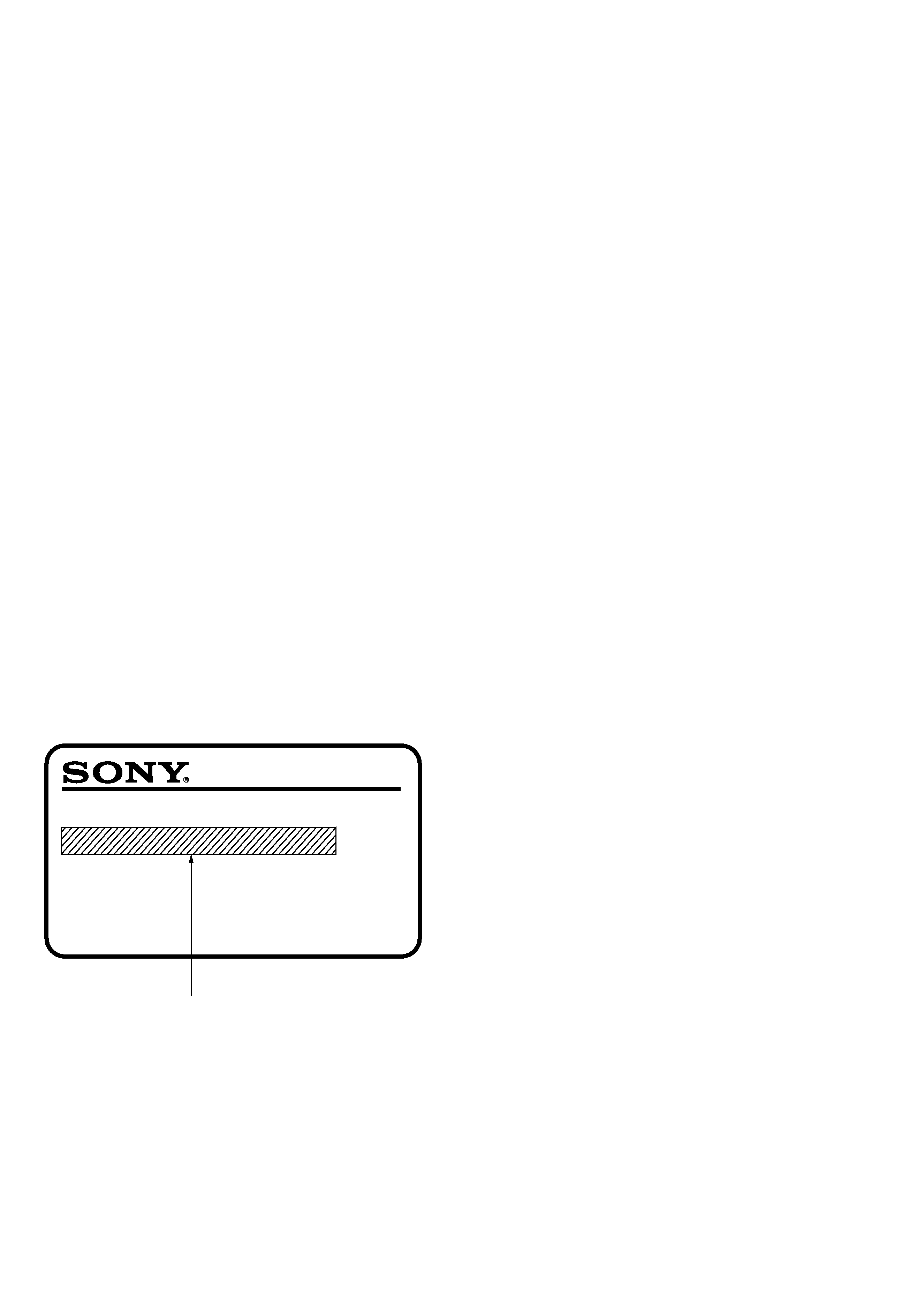
MODEL IDENTIFICATION
MODEL NO. HST-SE581
CASSETTE DECK RECEIVER
MODEL IDENTIFICATION
-- Model Number Label --
AEP, Singapore,
Malaysia : AC 230V ~ 50/60Hz 220W
Australian : AC 230V ~ 50Hz 220W
E : AC 110-120V, 220-240V selectable
~ 50/60Hz 220W
SAFETY-RELATED COMPONENT WARNING!!
COMPONENTS IDENTIFIED BY MARK
! OR DOTTED LINE WITH
MARK
! ON THE SCHEMATIC DIAGRAMS AND IN THE PARTS
LIST ARE CRITICAL TO SAFE OPERATION. REPLACE THESE
COMPONENTS WITH SONY PARTS WHOSE PART NUMBERS
APPEAR AS SHOWN IN THIS MANUAL OR IN SUPPLEMENTS
PUBLISHED BY SONY.
1. GENERAL ·········································································· 3
2. TEST MODE ······································································ 5
3. MECHANICAL ADJUSTMENTS ······························ 6
4. ELECTRICAL ADJUSTMENTS ································ 6
5. DIAGRAMS
5-1.
Circuit Boards Location ····················································· 9
5-2.
Block Diagram ································································· 11
5-3.
Schematic Diagram -- Main Section (1/2) -- ················· 13
5-4.
Schematic Diagram -- Main Section (2/2) -- ················· 15
5-5.
Printed Wiring Board -- Main Section -- ······················· 17
5-6.
Printed Wiring Board -- Display Section -- ··················· 19
5-7.
Schematic Diagram -- Display Section -- ······················ 21
5-8.
Printed Wiring Board -- SW Section -- ·························· 23
5-9.
Schematic Diagram -- SW Section -- ···························· 25
5-10. Printed Wiring Board -- Power Amp Section -- ············· 27
5-11. Schematic Diagram -- Power Amp Section -- ··············· 29
5-12. Printed Wiring Board -- Deck Section -- ······················· 31
5-13. Schematic Diagram -- Deck Section -- ·························· 33
5-14. Printed Wiring Board -- Power Transformer Section -- · 35
5-15. Schematic Diagram -- Power Transformer Section -- ··· 37
5-16. IC Block Diagrams ··························································· 39
5-17. IC Pin Function ································································ 41
6. EXPLODED VIEWS ······················································ 43
7. ELECTRICAL PARTS LIST ······································· 47
TABLE OF CONTENTS
Outputs
VIDEO1 (phono jacks):
voltage 250 mV, impedance 1 k
PHONES (stereo phone jack):
accepts low and high impedence headphones
Tape deck section
Track method
4-track, 2-channnel stereo
Frequency response
With DOLBY NR set to OFF
TYPE-I tape:
60-13,000 Hz,
± 3 dB
TYPE-II tape:
60-14,000 Hz,
± 3 dB
General
Power requirements
European, Singapore and Malaysian models:
230 V AC, 50 / 60 Hz
Australian model:
230 V AC, 50 Hz
E model:
110 120 V AC or
220 240 V AC, 50 / 60 Hz
(selectable)
Power consumption
220 W
Dimensions (w/h/d)
Approx. 430
× 330 × 355 mm
Mass
Approx.10.5 kg
Supplied accessories:
Remote RM-U581 (1)
Batteries (2)
AM loop antenna (1)
FM lead antenna (1)
Design and specifications are subject to change
without notice.
-- 3 --
SECTION 1
GENERAL
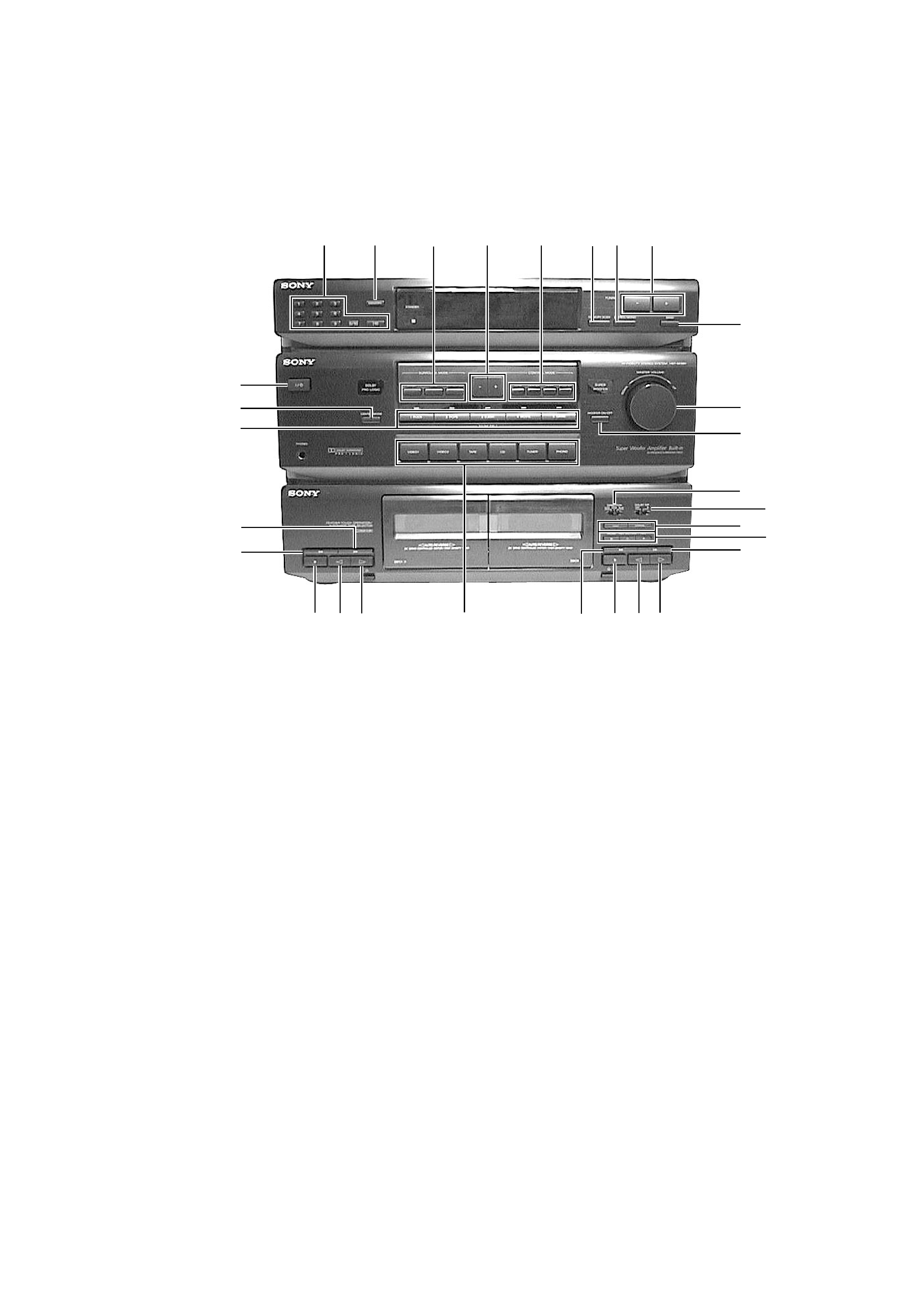
LOCATION AND FUNCTION OF CONTROLS
[FRONT PANEL]
1 10 KEY
2 MEMORY
3 SURROUND MODE (DOLBY/HALL/SIMULATED)
4 CONTROL MODE (/
+)
5 CONTROL MODE (TONE/CENTER/REAR/WOOFER)
6 MEMORY SCAN
7 STEREO/MONO
8 TUNING (/
+)
9 BAND
0 MASTER VOLUME
!¡ WOOFER ON/OFF
!TM DIRECTION (DECK B)
!£ DOLBY NR (DECK B)
!¢ DUBBING SPEED (HIGH/NORMAL) (DECK B)
! REC (PAUSE/REC MUTING/REC) (DECK B)
!§ ) (DECK B)
!¶ · (DECK B)
!· ª (DECK B)
!ª p (DECK B)
@º 0 (DECK B)
@¡ VIDEO 1/VIDEO 2/TAPE/CD/TUNER/PHONO
@TM · (DECK A)
@£ ª (DECK A)
@¢ p (DECK A)
@ 0 (DECK A)
@§ ) (DECK A)
@¶ SOUND FIELD
(1 ROCK/2 POPS/3 CLASSIC/4 MOVIE/5 GAME)
@· CENTER MODE
@ª POWER 1/u
1
2
3
45
6 78
9
0
!¡
!TM
!£
!¢
!
!§
!¶
!·
!ª
@º
@¡
@TM
@£
@¢
@
@§
@¶
@·
@ª
r
r
r
r
r
r
r
r
r
r
r
r
r
r
r
r
r
r
r
r
r
r
r
r
r
r
r
r
r
-- 4 --
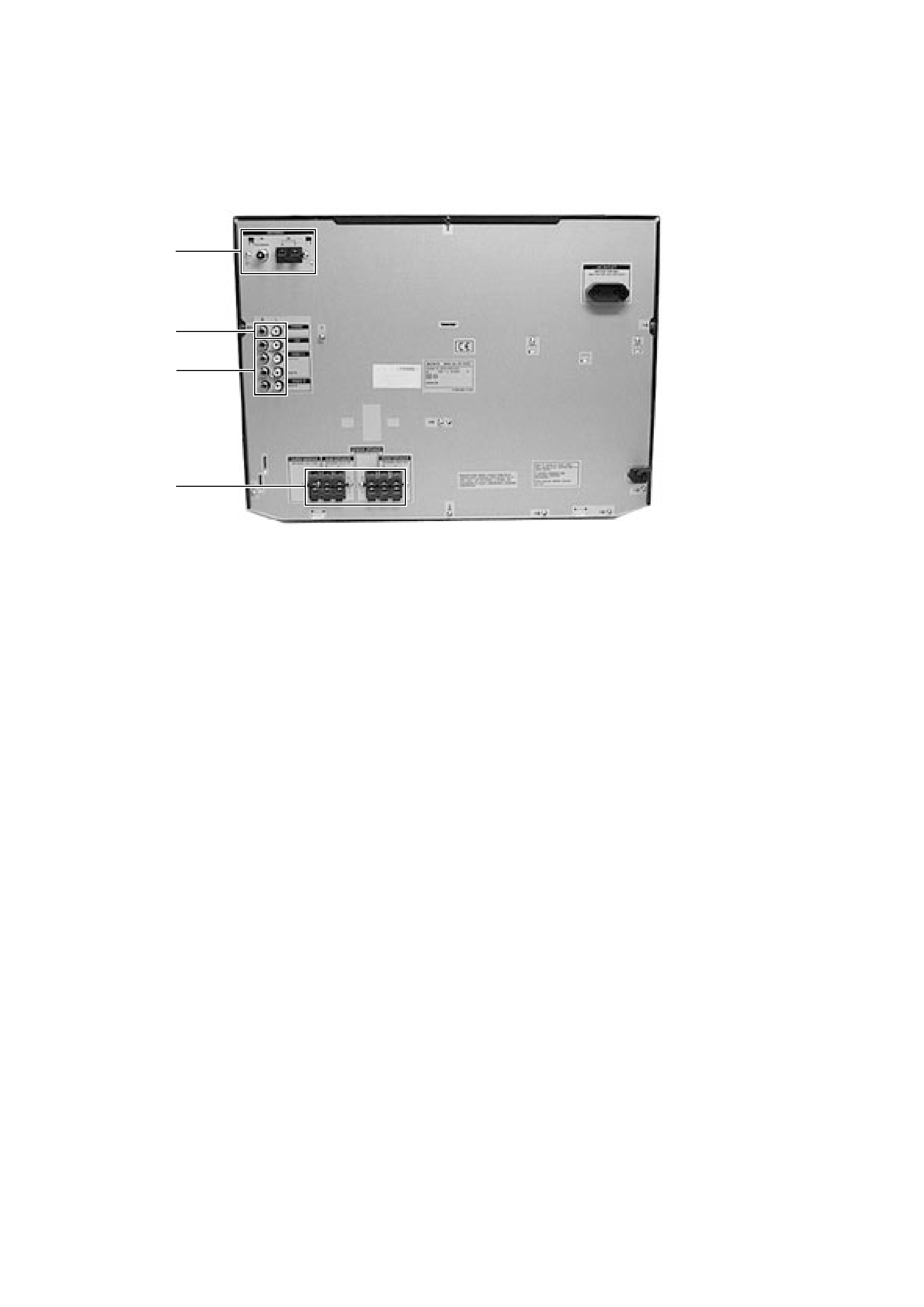
[REAR PANEL]
#º ANTENNA terminal
#¡ PHONO jack
#TM CD/VIDEO 1/VIDEO 2 jack
#£ SPEAKER terminal
#º
#¡
#TM
#£
r
r
r
r
Photo : AEP Model
-- 5 --
SECTION 2
TEST MODE
[Fluorescent Indicator Tube, LED All Lit, and Key Check Mode]
1. When the plug is inserted into the outlet while pressing the
MEMORY SCAN button, the fluorescent indicator tube and
LED will light up completely.
2. The mode changes as follows each time the BAND button and
WOOFER ON/OFF button are pressed together after 1.
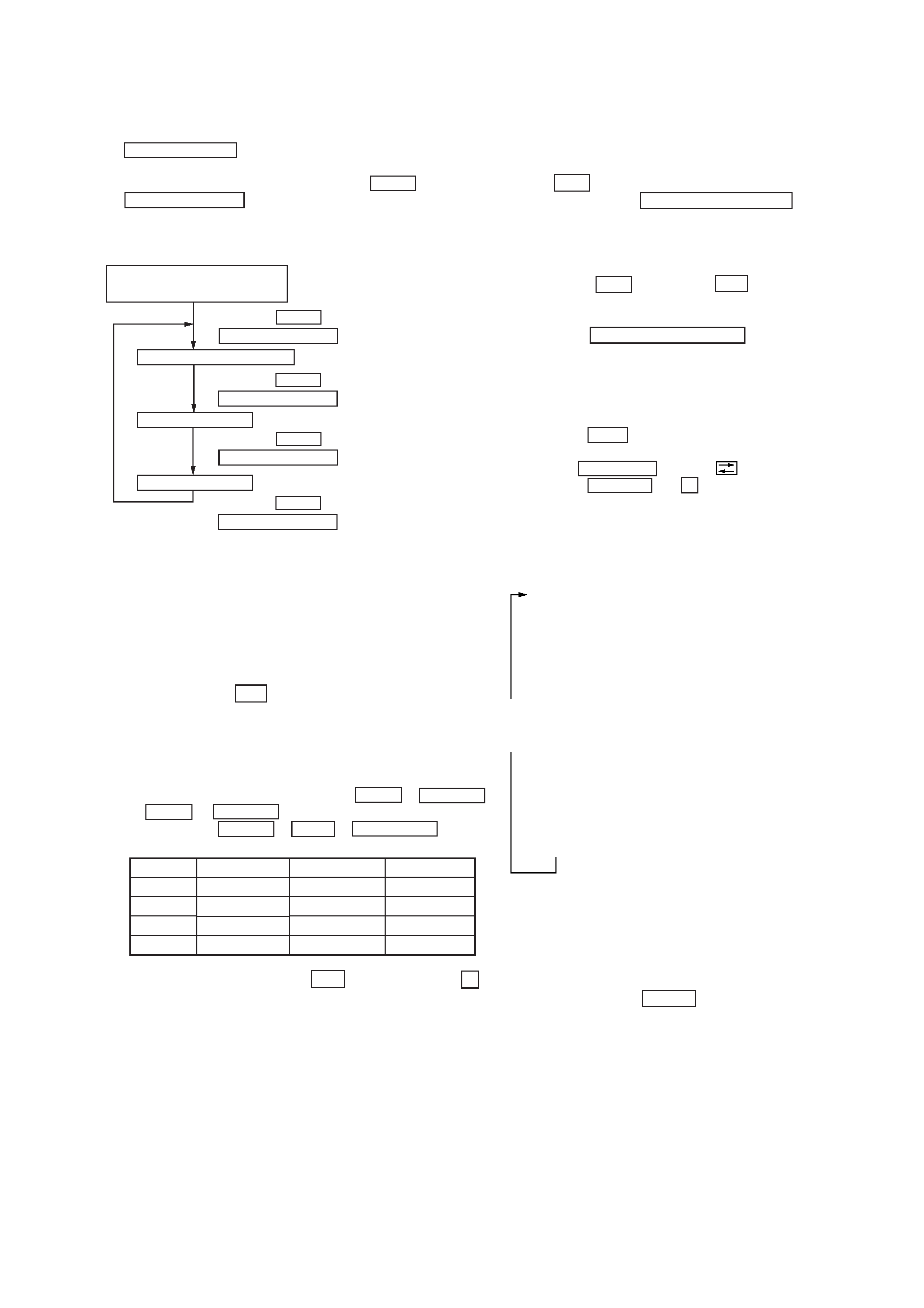
Sequence of Service Modes
*1 For checking if the fluorescent indicator tube and LED are lit
completely
*2 Model name and destination are shown in the destination display
mode.
*3 When the KEY check mode is set, "KEY 0"is displayed on the
fluorescent indicator tube. Each press of the button is counted.
(This excludes the
1/u button)
Buttons pressed once will not be counted when pressed again.
When all keys are pressed, "KEY END" appears.
*4 When the AMP check mode is set, "AMP" is displayed on the
fluorescent indicator tube.
Select any desired mode by pressing the TONE or CENTER
or REAR or WOOFER button. After a mode is selected,
press any of the DOLBY or HALL or SIMULATED button
as shown below to change the amplification level.
3. To exit the test mode, press the
1/u button, or press the p
(STOP) button of the deck A during the modes except the key
check mode.
[TC test mode]
1. Insert a playback tape into the deck A and a record tape into
the deck B.
2. While the power cable is disconnected from AC outlet, press
the
1/u switch.
3. While pressing the DUBBING SPEED HIGH button, connect
the power cable to the AC outlet.
Operation
Audio dubbing from deck A to Deck B starts.
When the
0 button or the ) button (during reverse
recording) of the deck B is pressed during dubbing, the tape
returns to the recording start point and playback starts.
When the DUBBING SPEED HIGH button is pressed during
dubbing, the high speed dubbing is performed.
[TC aging mode]
1. Turn on the main power.
2. Press the TAPE button. Insert a playback tape into the deck
A and a record tape into the deck B.
3. Set the DIRECTION switch to
.
4. Press the WOOFER and
p (STOP) button of the deck A at
the same time to enter the aging mode.
Operation
TONE
CENTER
REAR
WOOFER
DOLBY
10 dB
15 dB
15 dB
24 dB
HALL
0 dB
0 dB
0 dB
0 dB
SIMULATED
+10 dB
+6 dB
+6 dB
+8 dB
Fluorescent Indicator
Tube and LED Check Mode*1
Destination display mode*2
·
Press the BAND button and
WOOFER ON/OFF button at the same time.
KEY check mode*3
·
Press the BAND button and
WOOFER ON/OFF button at the same time.
·
Press the BAND button and
WOOFER ON/OFF button at the same time.
AMP check mode*4
·
Press the BAND button and
WOOFER ON/OFF button at the same time.
These operations are repeated.
5. How to exit the TC aging mode.
Press any keys related to the TC deck.
[Backup Clear Mode]
1. While pressing the DOLBY key, connect the power cable to
the AC outlet. All preset data is cleared.
Deck A rewinds (REW) up to the tape top,
Deck B rewinds (REW) up to the tape top,
Deck A plays back (FWD) for one minute, then stops (STOP)
momentarily,
Deck A plays back (FWD) for three minutes,
Deck A runs in fast forward (F. FWD) up to tape end,
Deck A plays back (REV) for one minute, then stops (STOP)
momentarily,
Deck A plays back (REV) for three minutes,
Deck A runs in fast reverse (REV) up to tape top,
Deck B plays back (FWD) for one minute, then stops (PAUSE)
momentarily,
Deck B records (FWD. RECORD) for three minutes,
Deck B runs in fast forward (F. FWD) up to tape end,
Deck B plays back (REV) for one minute, then stops (PAUSE)
momentarily,
Deck B records (REV. RECORD) for three minutes,
Deck B runs in fast reverse (REV) up to tape end,
<Repeat>