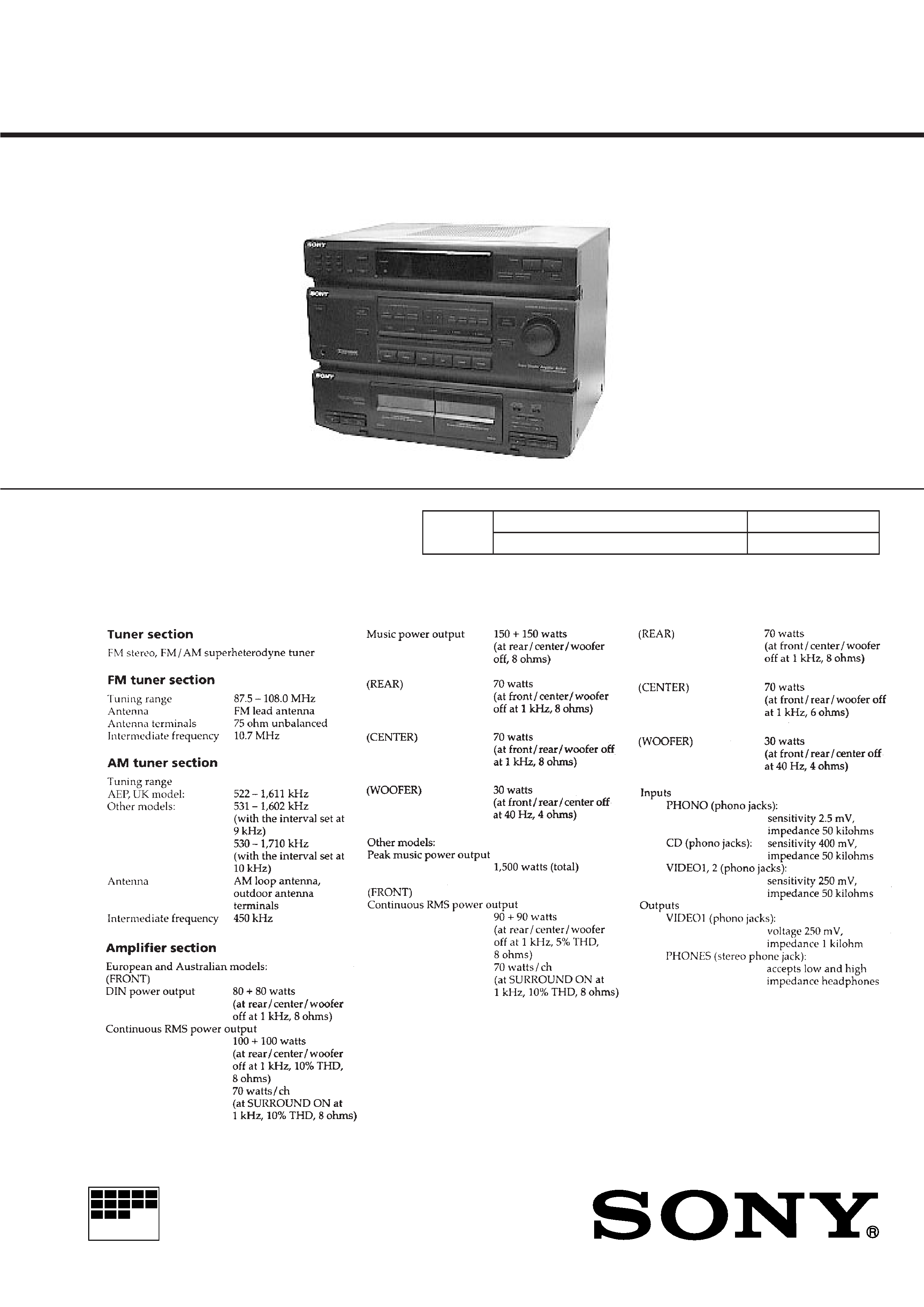
HST-471
AEP Model
UK Model
E Model
Australian Model
SERVICE MANUAL
CASSETTE DECK RECEIVER
MICROFILM
Tape deck
Model Name Using Similar Mechanism
HCD-GR8/RX90
Section
Tape Transport Mechanism Type
TCM-220WR2
SPECIFICATIONS
Manufactured under license from Dolby
Laboratories Licensing Corporation.
"DOLBY" and the double-D symbol
a are
trademarks of Dolby Laboratories Licensing
Corporation.
-- Continued on next page --
This set is the tunerdeck
and amplifier section
in SEN-R4720/R5750.
-- 2 --
TABLE OF CONTENTS
SAFETY-RELATED COMPONENT WARNING!!
COMPONENTS IDENTIFIED BY MARK
! OR DOTTED LINE WITH
MARK
! ON THE SCHEMATIC DIAGRAMS AND IN THE PARTS
LIST ARE CRITICAL TO SAFE OPERATION. REPLACE THESE
COMPONENTS WITH SONY PARTS WHOSE PART NUMBERS
APPEAR AS SHOWN IN THIS MANUAL OR IN SUPPLEMENTS
PUBLISHED BY SONY.
ATTENTION AU COMPOSANT AYANT RAPPORT
MODEL IDENTFICATION
-- Model Number Label --
AEP, UK : AC 220-230V ~ 50/60Hz 240W
Australian : AC 240V ~ 50Hz 240W
E, Singapore : AC 110-120, 220-240V selectable ~ 50/60Hz 240W
MODEL IDENTIFICATION
MODEL NO. HST-471
CASSETTE DECK RECEIVER
1.
GENERAL
· Tuner/Amp Section ···································································· 3
· Deck Section ·············································································· 3
2.
MECHANICAL ADJUSTMENTS ·························· 4
3.
ELECTRICAL ADJUSTMENTS ···························· 4
4.
DIAGRAMS
4-1.
Circuit Boards Location ····················································· 8
4-2.
Block Diagram ··································································· 9
4-3.
Schematic Diagram -- Deck Section -- ·························· 12
4-4.
Printed Wiring Board -- Deck Section -- ······················· 15
4-5.
Printed Wiring Board -- Main Section -- ······················· 17
4-6.
Schematic Diagram -- Main Section -- ·························· 19
4-7.
Schematic Diagram -- Display Section -- ······················ 23
4-8.
Printed Wiring Board -- Display Section -- ··················· 27
4-9.
Printed Wiring Board -- Power Section -- ····················· 30
4-10. Schematic Diagram -- Power Section -- ························ 33
4-11. IC Block Diagrams ··························································· 36
4-12. IC Pin Function ································································ 38
5.
REPAIR PARTS LIST
5-1.
Main Section ····································································· 40
5-2.
Front Panel Section ·························································· 41
5-3.
Tape Mechanism Deck Section-1
(TCM-220WR2) ······························································· 42
5-4.
Tapa Mechanism Deck Section-2
(TCM-220WR2) ······························································· 43
6.
ELECTRICAL PARTS LIST ··································· 44
-- 3 --
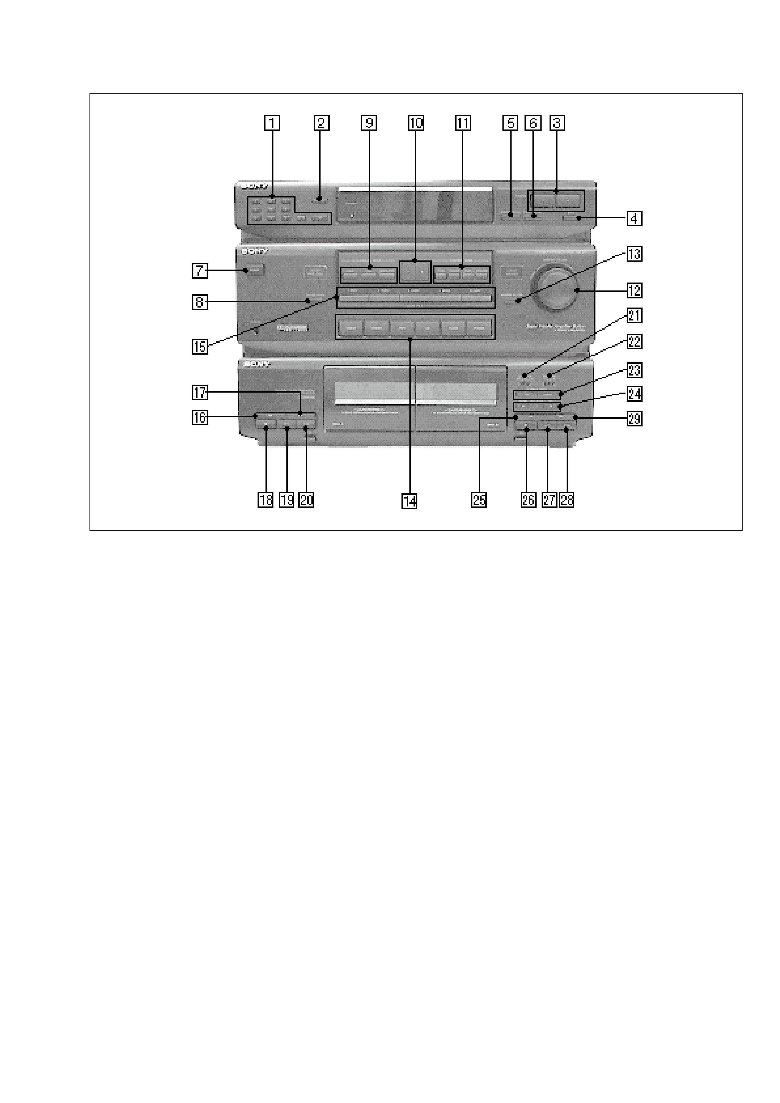
SECTION 1
GENERAL
· TUNER/AMP SECTION
1 10 KEY
2 MEMORY
3 TUNING (/+)
4 BAND
5 MEMORY SCAN
6 STEREO/MONO
7 POWER
8 CENTER MODE
9 SURROUND MODE (DOLBY/HALL/SIMULATED)
!º CONTROL MODE (/+)
!¡ CONTROL MODE
(TONE/CENTER/REAR/WOOFER)
!TM MASTER VOLUME
!£ WOOFER ON/OFF
!¢ VIDEO 1/VIDEO 2/TAPE/CD/TUNER/PHONO
! SOUND FIELD
(1 ROCK/2 POPS/3 CLASSIC/4 MOVIE/5 GAME)
· DECK SECTION
!§ 0 (DECK A)
!¶ ) (DECK A)
!· p (DECK A)
!ª ª (DECK A)
@º · (DECK A)
@¡ DIRECTION (DECK B)
@TM DOLBY NR (DECK B)
@£ DUBBING SPEED (HIGH/NORMAL) (DECK B)
@¢ REC (PAUSE/REC MUTE/REC) (DECK B)
@ 0 (DECK B)
@§ p (DECK B)
@¶ ª (DECK B)
@· · (DECK B)
@ª ) (DECK B)
-- 4 --
SECTION 2
MECHANICAL ADJUSTMENTS
SECTION 3
ELECTRICAL ADJUSTMENTS
PRECAUTION
1.
Clean the following parts with a denatured-alcohol-moistened
swab:
record/playback head
pinch roller
erase head
rubber belts
capstan
idlers
2.
Demagnetize the record/playback head with a head
demagnetizer.
3.
Do not use a magnetized screwdriver for the adjustments.
4.
After the adjustments, apply suitable locking compound to the
parts adjusted.
5.
The adjustments should be performed with the rated power
supply voltage unless otherwise noted.
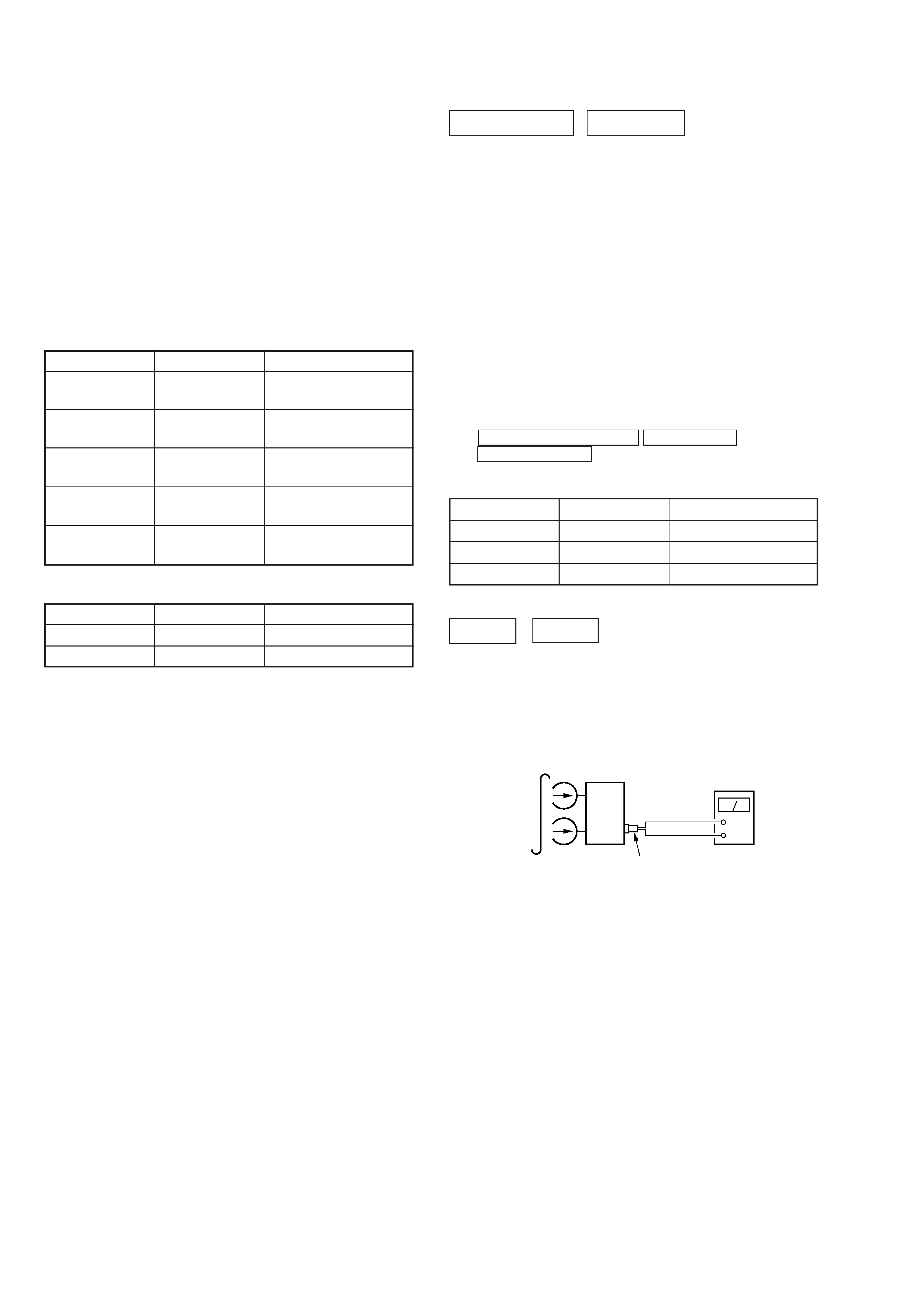
· Torque Measurement
· Tape Tension Measurement
DECK SECTION
0 dB=0.775V
1.
Demagnetize the record/playback head with a head
demagnetizer. (Do not bring the head demagnetizer close to
the erase head.)
2.
Do not use a magnetized screwdriver for the adjustments.
3.
After the adjustments, apply suitable locking compound to the
parts adjust.
4.
The adjustments should be performed with the rated power
supply voltage unless otherwise noted.
5.
The adjustments should be performed in the order given in this
service manual. (As a general rule, playback circuit adjustment
should be completed before performing recording circuit
adjustment.)
6.
The adjustments should be performed for both L-CH and R-
ch.
7.
Switches and controls should be set as follows unless otherwise
specified.
8.
Set to test mode. (Press key switch same time
SPECTRUM ANALYZER
ENTER/NEXT and
EFFECT ON/OFF button.)
·
Test Tape
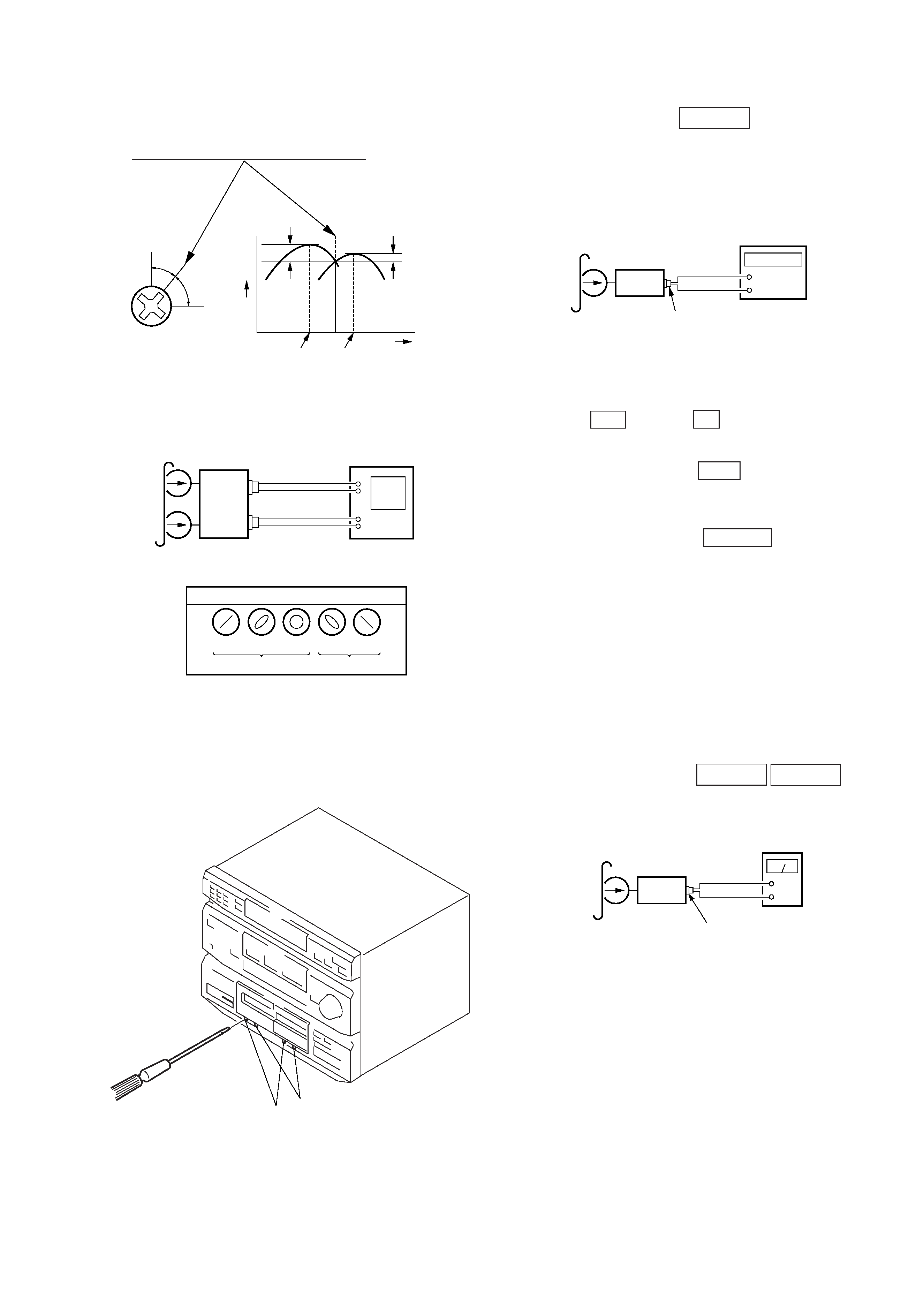
Record/Playback Head Azimuth Adjustment
DECK A
DECK B
Note : Perform this adjustments for both decks. Remove the covers
of cassette holders.
Procedure:
1.
Mode: Playback (FWD)
Mode
Torque Meter
Meter Reading
Forward
CQ-102C
36 to 61g·cm
(0.50 0.84 oz·inch)
Forward
CQ-102C
2 to 6g·cm
Back Tension
(0.026 0.082 oz·inch)
Reverse
CQ-102RC
36 to 61g·cm
(0.50 0.84 oz·inch)
Reverse
CQ-102RC
2 to 6g·cm
Back Tension
(0.026 0.082 oz·inch)
FF, REW
CQ-201B
61 to 143g·cm
(0.85 1.98 oz·inch)
Mode
Tension Meter
Meter Reading
Forward
CQ-403A
more than 100 g (3.53 oz)
Reverse
CQ-403R
more than 100 g (3.53 oz)
Tape
Signal
Used for
P-4-A100
10 kHz, 10 dB
Azimuth Adjustment
WS-48B
3 kHz, 0dB
Tape Speed Adjustment
P-4-L300
315 Hz, 0dB
Level Adjustment
set
rear panel
VIDEO1
AUDIO OUT connector
(L: L-CH)
(R: R-CH)
+
level meter
test tape
P-4-A100
(10 kHz, 10 dB)
-- 5 --
2.
Turn the adjustment screw and check output peaks. If the peaks
do not match for L-CH and R-CH, turn the adjustment screw
so that outputs match within 1dB of peak.
3.
Mode: Playback (FWD)
4.
Repeat steps 1 to 3 in playback (REV) mode.
5.
After the adjustments, apply suitable locking compound to the
pats adjusted.
Adjustment Location:
Record/Playback Head (Deck A and B)
and main board.
reverse
forward
Tape Speed Adjustment
DECK A
Note: Start the Tape Speed adjustment as below after setting to the
test mode.
Procedure:
Mode: Playback (FWD)
1.
Insert the WS-48B into the deck A and the blank tape into the
deck B.
2.
Press the REC button and
· button on the deck B. Then
the deck B is at recording mode.
3.
Set the deck A to playback mode.
4.
Press the DUBBING SPEED HIGH button in playback mode.
Then at HIGH speed mode.
5.
Adjust RV652 on the AUDIO board do that frequency counter
reads 6,000 ± 90 Hz.
6.
Press the DUBBING SPEED NORMAL button in playback
mode.
Then at NORMAL speed mode.
7.
Adjust RV651 on the AUDIO board so that frequency counter
reads 3,000 ± 90Hz.
8.
Frequency difference between deck A and deck B the beginning
of the tape should be within ± 1.5 %.
Adjustment Location: AUDIO board
Sample Value of Wow and flutter
W.RMS (JIS) within 0.3%
(test tape: WS-48B)
Playback level Adjustment
DECK A
DECK B
Procedure:
Mode: Playback (FWD)
Deck A is RV311 (L-CH) and RV411 (R-CH), Deck B is RV301
(L-CH) and RV401 (R-CH) so that adjustment within adjustment
level as follows.
Adjustment Level:
VIDEO1 AUDIO OUT PB level: 301.5 to 338.3 mV (8.2 to
7.2 dB) level difference between the channels: within ± 0.5
dB
Adjustment Location: AUDIO and main boards
Screw
position
L-CH
peak
within
1dB
output
level
L-CH
peak
R-CH
peak
within
1dB
Screw
position
R-CH
peak
set
test tape
P-4-A100
(10kHz, 10dB)
oscilloscope
L
R
V
waveform of oscilloscope
in phase 45
°
90
° 135° 180°
good
wrong
rear panel
VIDEO1
AUDIO OUT connector
H
+
set
test tape
WS-48B
(3 kHz, 0 dB)
frequency counter
rear panel
VIDEO1
AUDIO OUT connector
(L: L-CH)
(R: R-CH)
+
level meter
set
test tape
P-4-L300
(315 Hz, 0 dB)
rear panel
VIDEO1
AUDIO OUT connector
(L: L-CH)
(R: R-CH)