SERVICE MANUAL
SPECIFICATIONS
CHASSIS
AEP Model
Chassis No. SCC-L35A-A
TRINITRON® COLOR COMPUTER DISPLAY
HMD-A420
CRT
0.24 mm aperture grille pitch (center)
19 inches measured diagonally
90-degree deflection
FD Trinitron
Viewable image size
Approx. 365
× 274 mm (w/h)
(14 3/8
× 10 7/8 inches)
18.0" viewing image
Resolution
Maximum
Horizontal: 1800 dots
Vertical: 1440 lines
Recommended
Horizontal: 1280 dots
Vertical: 1024 lines
Standard image area
Approx. 352
× 264 mm (w/h)
(13 7/8
× 10 1/2 inches)
Deflection frequency*
Horizontal: 30 to 96 kHz
Vertical: 48 to 120 Hz
AC input voltage/current
100 240 V, 50 60 Hz, 2.3 1.0 A
Power consumption
Max. 150 W
Dimensions
Approx. 497
× 458 × 469 mm
(w/h/d)
(19 5/8
× 18 1/8 × 18 1/2 inches)
Mass
Approx. 26 kg (57 lb 5 oz)
Plug and Play
DDC1/DDC2B/DDC2Bi
* Recommended horizontal and vertical timing condition
· Horizontal sync width should be more than 1.0
µsec.
· Horizontal blanking width should be more than 3.0
µsec.
· Vertical blanking width should be more than 500
µsec.
Design and specifications are subject to change without notice.
H1
HMD-A420
2
LEAKAGE TEST
The AC leakage from any exposed metal part to earth ground
and from all exposed metal parts to any exposed metal part hav-
ing a return to chassis, must not exceed 0.5 mA (500
microamperes).
Leakage current can be measured by any one of three methods.
1. A commercial leakage tester, such as the Simpson 229 or
RCA WT-540A. Follow the manufacturers' instructions to
use these instruments.
2. A battery-operated AC milliammeter. The Data Precision
245 digital multimeter is suitable for this job.
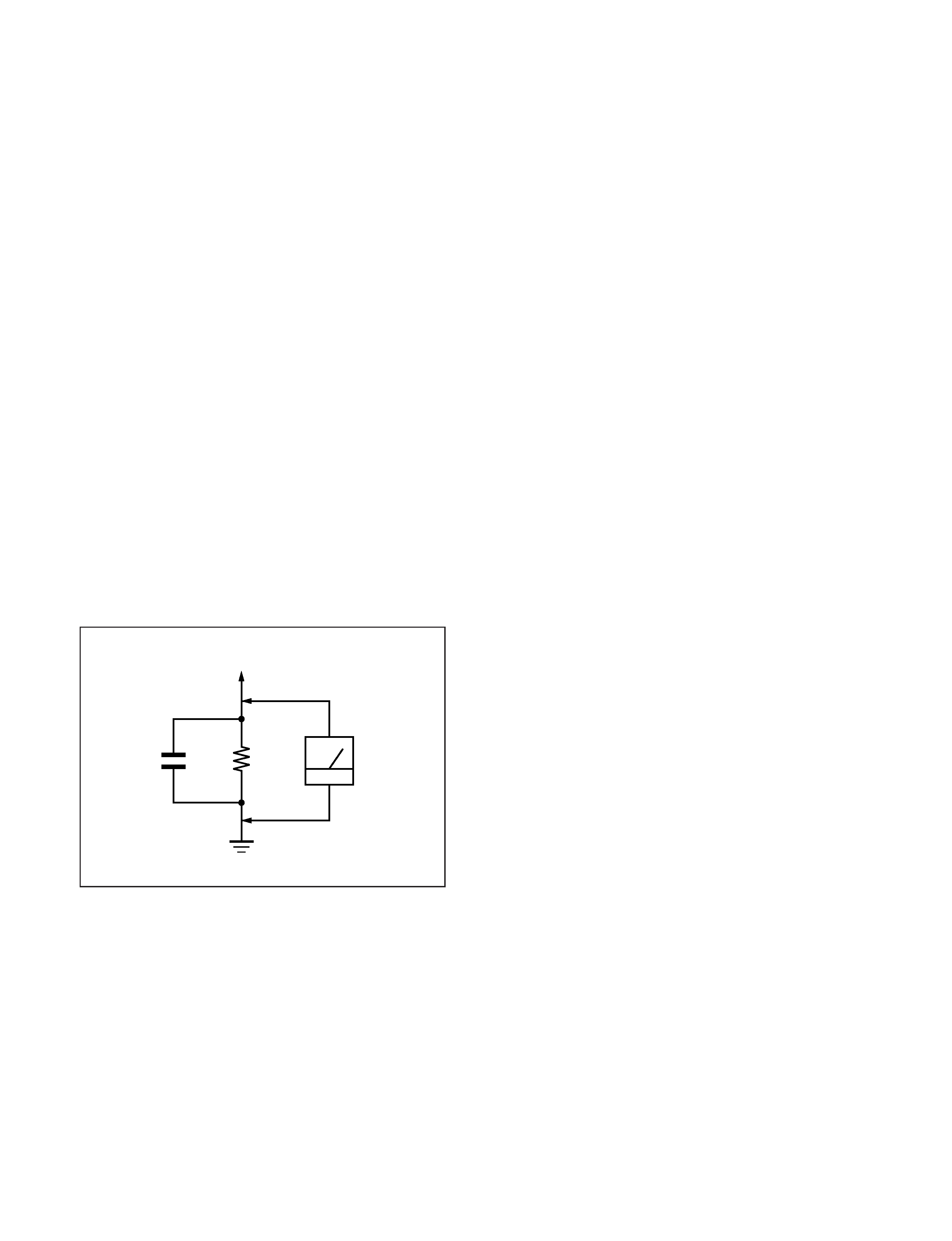
3. Measuring the voltage drop across a resistor by means of a
VOM or battery-operated AC voltmeter. The "limit" indica-
tion is 0.75 V, so analog meters must have an accurate low-
voltage scale. The Simpson 250 and Sanwa SH-63Trd are
examples of a passive VOMs that are suitable. Nearly all
battery operated digital multimeters that have a 2 V AC
range are suitable. (See Fig. A)
WARNING!!
NEVER TURN ON THE POWER IN A CONDITION IN
WHICH THE DEGAUSS COIL HAS BEEN REMOVED.
SAFETY-RELATED COMPONENT WARNING!!
COMPONENTS IDENTIFIED BY SHADING AND MARK
0 ON THE SCHEMATIC DIAGRAMS, EXPLODED
VIEWS AND IN THE PARTS LIST ARE CRITICAL FOR
SAFE OPERATION. REPLACE THESE COMPONENTS
WITH SONY PARTS WHOSE PART NUMBERS AP-
PEAR AS SHOWN IN THIS MANUAL OR IN SUPPLE-
MENTS PUBLISHED BY SONY. CIRCUIT ADJUST-
MENTS THAT ARE CRITICAL FOR SAFE OPERATION
ARE IDENTIFIED IN THIS MANUAL. FOLLOW THESE
PROCEDURES WHENEVER CRITICAL COMPONENTS
ARE REPLACED OR IMPROPER OPERATION IS SUS-
PECTED.
AVERTISSEMENT!!
NE JAMAIS METTRE SOUS TENSION QUAND LA
BOBINE DE DEMAGNETISATION EST ENLEVÉE.
ATTENTION AUX COMPOSANTS RELATIFS À LA
SÉCURITÉ!!
LES COMPOSANTS IDENTIFIÉS PAR UNE TRAME ET
UNE MARQUE 0 SONT CRITIQUES POUR LA SÉCURITÉ.
NE LES REMPLACER QUE PAR UNE PIÈCE PORTANT LE
NUMÉRO SPECIFIÉ. LES RÉGLAGES DE CIRCUIT DONT
L'IMPORTANCE EST CRITIQUE POUR LA SÉCURITÉ DU
FONCTIONNEMENT SONT IDENTIFIÉS DANS LE
PRÉSENT MANUEL. SUIVRE CES PROCÉDURES LORS
DE CHAQUE REMPLACEMENT DE COMPOSANTS CRI-
TIQUES, OU LORSQU'UN MAUVAIS FONCTIONNEMENT
EST SUSPECTÉ.
After correcting the original service problem, perform the fol-
lowing safety checks before releasing the set to the customer:
1. Check the area of your repair for unsoldered or poorly-sol-
dered connections. Check the entire board surface for solder
splashes and bridges.
2. Check the interboard wiring to ensure that no wires are
"pinched" or contact high-wattage resistors.
3. Check that all control knobs, shields, covers, ground straps,
and mounting hardware have been replaced. Be absolutely
certain that you have replaced all the insulators.
4. Look for unauthorized replacement parts, particularly tran-
sistors, that were installed during a previous repair. Point
them out to the customer and recommend their replacement.
5. Look for parts which, though functioning, show obvious
signs of deterioration. Point them out to the customer and
recommend their replacement.
6. Check the line cords for cracks and abrasion. Recommend
the replacement of any such line cord to the customer.
7. Check the B+ and HV to see if they are specified values.
Make sure your instruments are accurate; be suspicious of
your HV meter if sets always have low HV.
8. Check the antenna terminals, metal trim, "metallized"
knobs, screws, and all other exposed metal parts for AC
Leakage. Check leakage as described below.
Fig. A. Using an AC voltmeter to check AC leakage.
SAFETY CHECK-OUT
1.5 k
0.15
µF
AC
Voltmeter
(0.75 V)
To Exposed Metal
Parts on Set
Earth Ground
HMD-A420
3
POWER SAVING FUNCTION
DIAGNOSIS
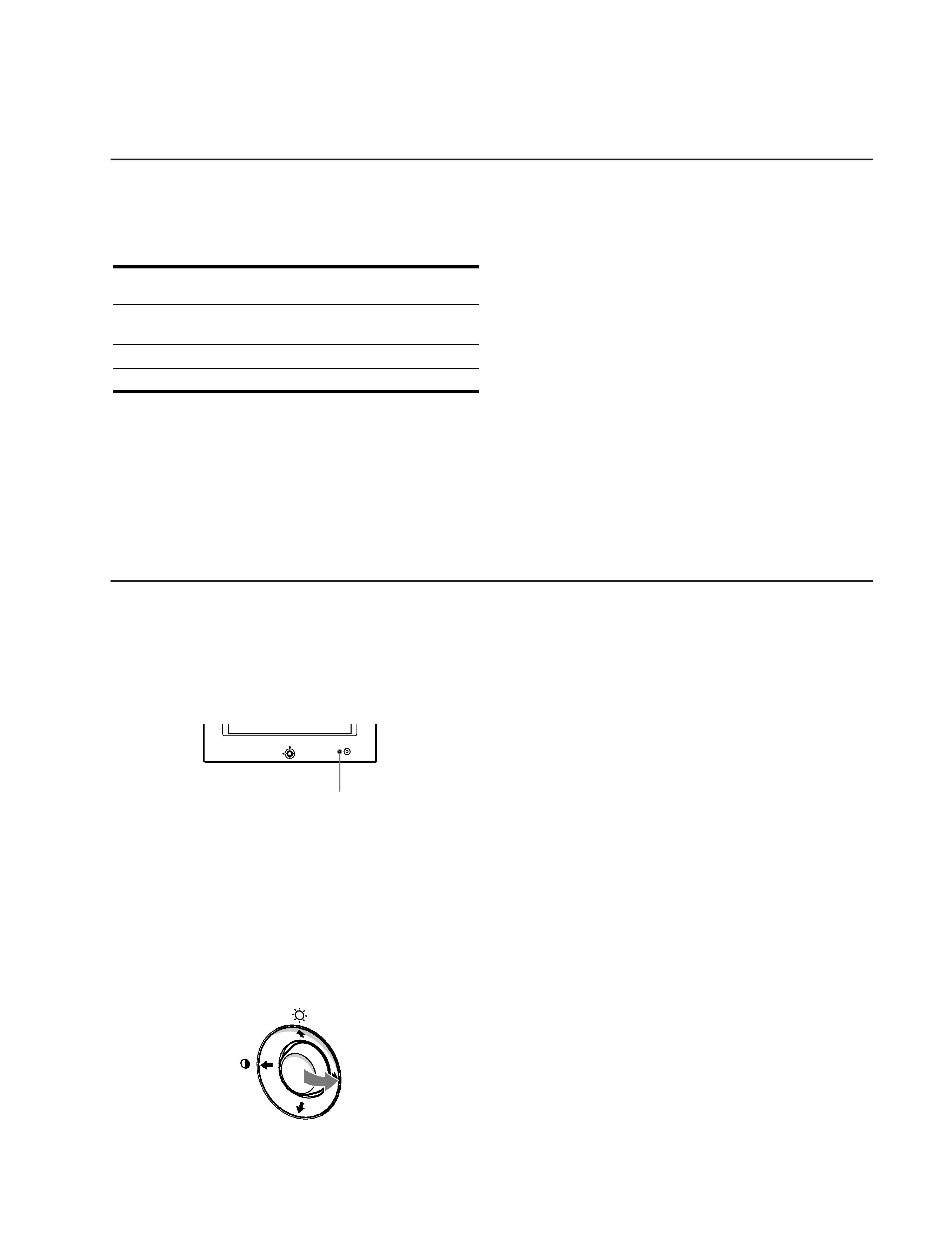
This monitor is equipped with a self-diagnosis function. If there is
a problem with your monitor or computer, the screen will go
blank and the ! (power) indicator will either light up green or
flash orange. If the ! (power) indicator is lit in orange, the
computer is in power saving mode. Try pressing any key on the
keyboard.
If the ! (power) indicator is green
1 Disconnect the video input cable or turn off the
connected computer.
2 Press the ! (power) button twice to turn the monitor
off and then on.
3 Move the control button , for 2 seconds before the
monitor enters power saving mode.
If all four color bars appear (white, red, green, blue), the monitor
is working properly. Reconnect the video input cable and check
the condition of your computer.
If the color bars do not appear, there is a potential monitor failure.
Inform your authorized Sony dealer of the monitor's condition.
If the ! (power) indicator is flashing orange
Press the ! (power) button twice to turn the monitor off
and then on.
If the ! (power) indicator lights up green, the monitor is working
properly.
If the ! (power) indicator is still flashing, there is a potential
monitor failure. Count the number of seconds between orange
flashes of the ! (power) indicator and inform your authorized
Sony dealer of the monitor's condition. Be sure to note the model
name and serial number of your monitor. Also note the make and
model of your computer and video board.
MENU
! (power) indicator
MENU
This monitor meets the power-saving guidelines set by VESA,
ENERGY STAR, and NUTEK. If no signal is received by the
monitor from the connected computer, the monitor will
automatically reduce power consumption as shown below.
*
Figures reflect power consumption when no USB compatible
peripherals are connected to the monitor.
** When your computer enters the "active off" mode, the input signal is
cut and NO INPUT SIGNAL appears on the screen. After 20 seconds,
the monitor enters the power saving mode.
Power mode
Power
consumption*
! (power)
indicator
normal
operation
150 W
green
active off**
3 W
orange
power off
0 W
off
HMD-A420
4
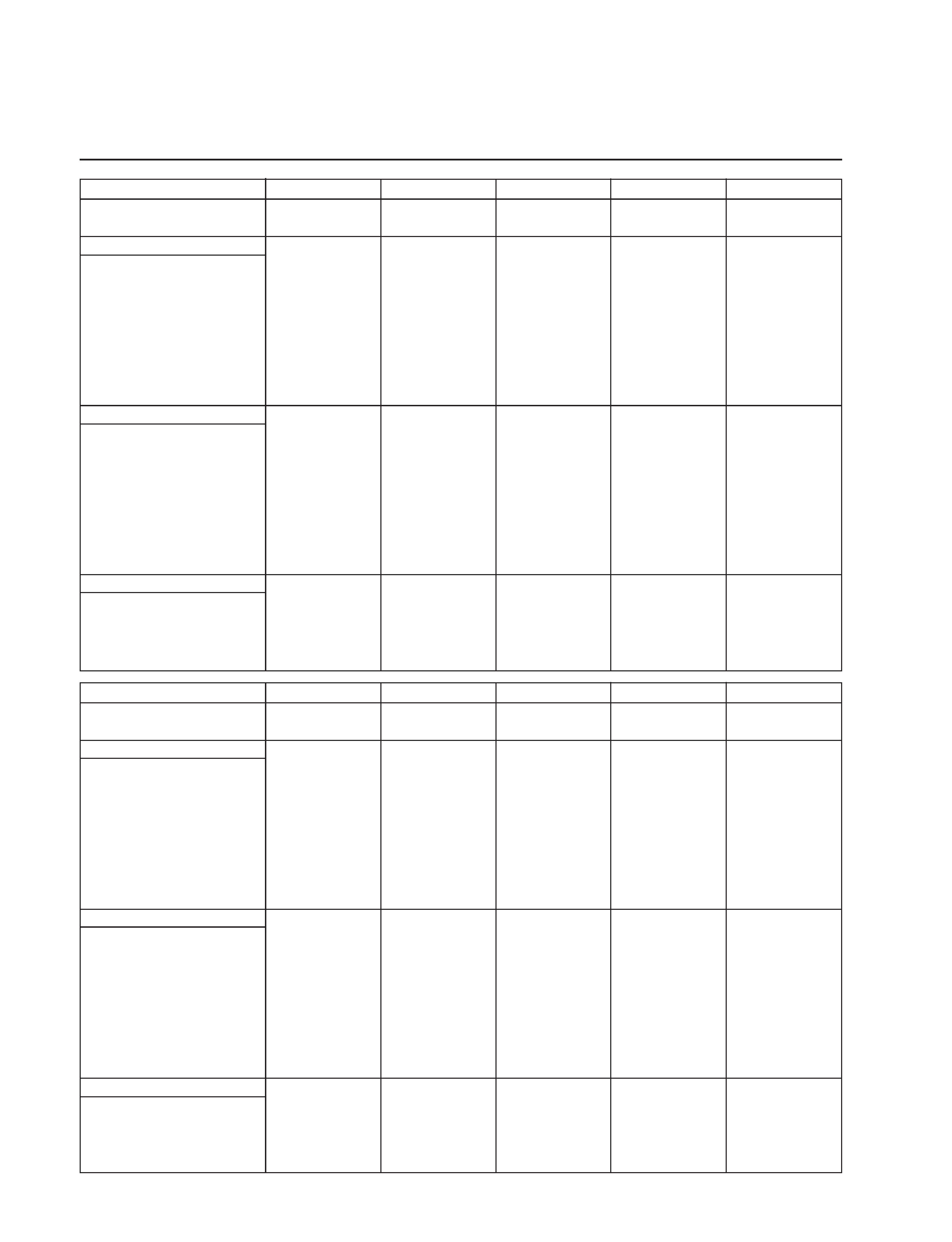
TIMING SPECIFICATION
MODE AT PRODUCTION
MODE 1
MODE 2
MODE 3
MODE 4
MODE 5
RESOLUTION
640 X 480
640 X 480
720 X 400
800 X 600
832 X 624
CLOCK
25.175 MHz
36.000 MHz
28.321 MHz
56.250 MHz
57.283 MHz
-- HORIZONTAL --
H-FREQ
31.469 kHz
43.269 kHz
31.468 kHz
53.674 kHz
49.725 kHz
usec
usec
usec
usec
usec
H. TOTAL
31.778
23.111
31.779
18.631
20.111
H. BLK
6.356
5.333
6.356
4.409
5.586
H. FP
0.636
1.556
0.636
0.569
0.559
H. SYNC
3.813
1.556
3.813
1.138
1.117
H. BP
1.907
2.222
1.907
2.702
3.910
H. ACTIV
25.422
17.778
25.423
14.222
14.524
-- VERTICAL --
V. FREQ(HZ)
59.940 Hz
85.008 Hz
70.084 Hz
85.061 Hz
74.550 Hz
lines
lines
lines
lines
lines
V. TOTAL
525
509
449
631
667
V. BLK
45
29
49
31
43
V. FP
10
1
12
1
1
V. SYNC
2
3
2
3
3
V. BP
33
25
35
27
39
V. ACTIV
480
480
400
600
624
-- SYNC --
INT(G)
NO
NO
NO
NO
NO
EXT(H/V)/POLARITY
YES N/N
YES N/N
YES N/P
YES N/P
YES N/N
EXT(CS)/POLARITY
NO
NO
NO
NO
NO
INT/NON INT
NON INT
NON INT
NON INT
NON INT
NON INT
MODE AT PRODUCTION
MODE 6
MODE 7
MODE 8
MODE 9
MODE 10
RESOLUTION
1024 X 768
1152 X 870
1280 X 1024
1280 X 1024
1600 X 1200
CLOCK
94.500 MHz
100.000 MHz
135.000 MHz
157.500 MHz
202.500 MHz
-- HORIZONTAL --
H-FREQ
68.677 kHz
68.681 kHz
79.976 kHz
91.146 kHz
93.750 kHz
usec
usec
usec
usec
usec
H. TOTAL
14.561
14.560
12.504
10.971
10.667
H. BLK
3.725
3.040
3.022
2.844
2.765
H. FP
0.508
0.320
0.119
0.406
0.316
H. SYNC
1.016
1.280
1.067
1.016
0.948
H. BP
2.201
1.440
1.837
1.422
1.501
H. ACTIV
10.836
11.520
9.481
8.127
7.901
-- VERTICAL --
V. FREQ(HZ)
84.997 Hz
75.062 Hz
75.025 Hz
85.024 Hz
75.000 Hz
lines
lines
lines
lines
lines
V. TOTAL
808
915
1066
1072
1250
V. BLK
40
45
42
48
50
V. FP
1
3
1
1
1
V. SYNC
3
3
2
3
3
V. BP
36
39
38
44
46
V. ACTIV
768
870
1024
1024
1200
-- SYNC --
INT(G)
NO
NO
NO
NO
NO
EXT(H/V)/POLARITY
YES P/P
YES N/N
YES P/P
YES P/P
YES P/P
EXT(CS)/POLARITY
NO
NO
NO
NO
NO
INT/NON INT
NON INT
NON INT
NON INT
NON INT
NON INT
2000.8.16 VER.

HMD-A420
5
TABLE OF CONTENTS
Section
Title
Page
1. GENERAL .................................................................. 1-1
2. DISASSEMBLY
2-1.
Bucket Assembly Removal ................................. 2-1
2-2.
A Board Removal ................................................ 2-1
2-3.
D Board Removal ................................................ 2-2
2-4.
Service Position .................................................... 2-3
2-5.
H Board Removal ................................................. 2-4
2-6.
Picture Tube Removal .......................................... 2-4
2-7.
Harness Location .................................................. 2-5
3. SAFETY RELATED ADJUSTMENT ............. 3-1
4. ADJUSTMENTS ...................................................... 4-1
5. DIAGRAMS
5-1.
Block Diagrams ................................................... 5-1
5-2.
Frame Schematic Diagram .................................. 5-5
5-3.
Circuit Boards Location ...................................... 5-6
5-4.
Schematic Diagrams and Printed Wiring Boards .. 5-7
(1)
Schematic Diagram of H Board ......................... 5-8
(2)
Schematic Diagram of A Board ......................... 5-9
(3)
Schematic Diagrams of
D (a, b, c, d, e, f) Board .................... 5-11
5-5.
Semiconductors .................................................. 5-23
6. EXPLODED VIEWS
6-1.
Chassis ................................................................. 6-1
6-2.
Picture Tube ........................................................ 6-2
6-3.
Packing Materials ................................................ 6-3
7. ELECTRICAL PARTS LIST ............................ 7-1