SERVICE MANUAL
17VC CHASSIS
Design and specifications are subject to change without notice.
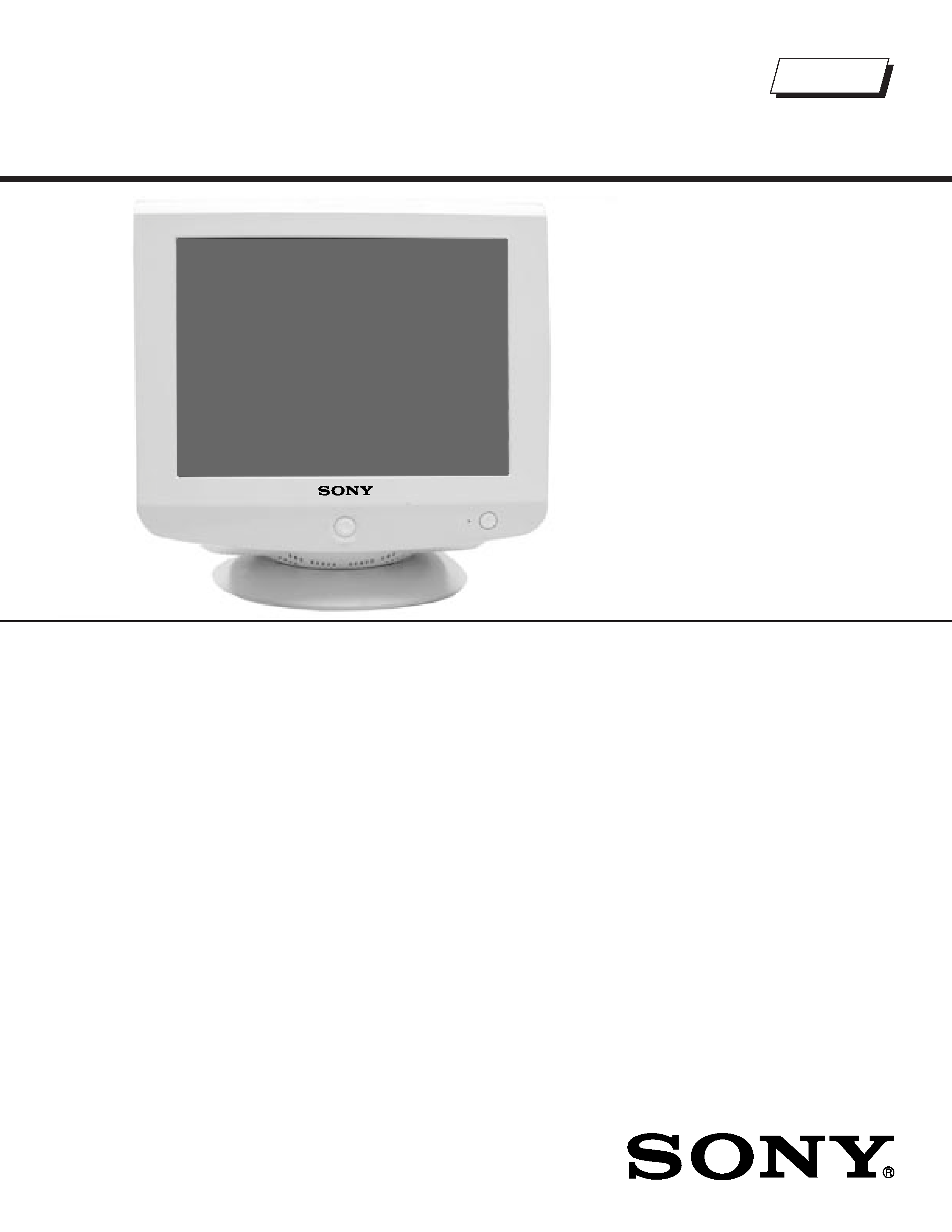
TRINITRON® COLOR MONITOR
HMD-A240R
US/Canada Model
Chassis No: SCC-L38PA
HMD-A240R
9-978-992-01
Picture tube
0.24 mm aperture grill pitch (center)
17 inches measured diagonally
90-degree deflection
Video image area
(16" maximum viewing image)
Approx. 327 X 243 mm (w/h)
(127/8 x 95/8 inches)
Resolution
Horizontal: Max. 1280 dots
Vertical: Max. 1024 lines
Standard image area Approx. 312 x 234 mm (w/h)
(123/8 x 91/4 inches)
Input signal
Video
Analog RGB (75 ohms typical)
0.7 Vp-p, ±5%, Positive
Sync
Separate HD/VD,
TTL Polarity Free
External Composite,
TTL Polarity Free
(2k ohms impedance)
Sync on Green
Power Consumption
100 W
Deflection frequency
Horizontal: 30 to 70 kHz
Vertical: 48 to 120 Hz
AC input voltage/current 100 to 120 V, 50/60 Hz, 1.7A
Dimensions
402 x 418 x 421 mm (w/h/d)
(157/8 x 161/2 x 165/8 inches)
Mass
Approx. 19 kg (41 lb 9 oz.)
Trinitron
SPECIFICATIONS
Self Diagnosis
Supported model

-- 3 --
HMD-A240R
TABLE OF CONTENTS
POWER MANAGEMENT ....................................................................................................................... 4
SELF DIAGNOSIS FUNCTION.............................................................................................................. 4
TIMING SPECIFICATION....................................................................................................................... 4
WARNINGS AND CAUTIONS................................................................................................................ 5
SAFETY CHECK-OUT ........................................................................................................................... 6
SECTION 1: DISASSEMBLY
1-1. Cabinet Removal............................................................................................................................ 7
1-2. Service Position.............................................................................................................................. 7
1-3. A & D Board Removal.................................................................................................................... 8
1-4. Picture Tube Removal .................................................................................................................... 9
ANODE CAP REMOVAL ................................................................................................................ 9
SECTION 2: SAFETY RELATED ADJUSTMENTS
2-1. HV Regulator Check..................................................................................................................... 10
2-2. HV Protector Circuit Check........................................................................................................... 10
2-3. Beam Protector Check (Software Logic) ..................................................................................... 10
2-4. B+ Voltage Check......................................................................................................................... 10
SECTION 3: ADJUSTMENTS
3-1. Landing Rough Adjustment ...........................................................................................................11
3-2. Landing Fine Adjustment...............................................................................................................11
3-3. Convergence Rough Adjustment...................................................................................................11
3-4. Convergence and V. Key (H. Trp) Fine Adjustment.......................................................................11
3-5. Vertical and Horizontal Position and Size Specification ............................................................... 12
3-6. Focus Adjustment......................................................................................................................... 13
3-7. Digital Convergence Adjustment .................................................................................................. 13
3-8. Convergence Specification........................................................................................................... 13
SECTION 4: DIAGRAMS
4-1. Circuit Boards Location ................................................................................................................ 14
4-2. Printed Wiring Board and Schematic Diagram Information.......................................................... 14
4-3. Block Diagrams and Schematics.................................................................................................. 15
A Board Schematic Diagram......................................................................................................... 17
D Board Schematic Diagram........................................................................................................ 18
H Board Schematic Diagram........................................................................................................ 23
J Board Schematic Diagram......................................................................................................... 24
4-4. Semiconductors............................................................................................................................ 25
SECTION 5: EXPLODED VIEWS
5-1. Picture Tube ................................................................................................................................. 26
5-2. Chassis......................................................................................................................................... 27
5-3. Packing Materials ......................................................................................................................... 28
SECTION 6: ELECTRICAL PARTS LIST............................................................................................................ 29
-- 4 --
HMD-A240R
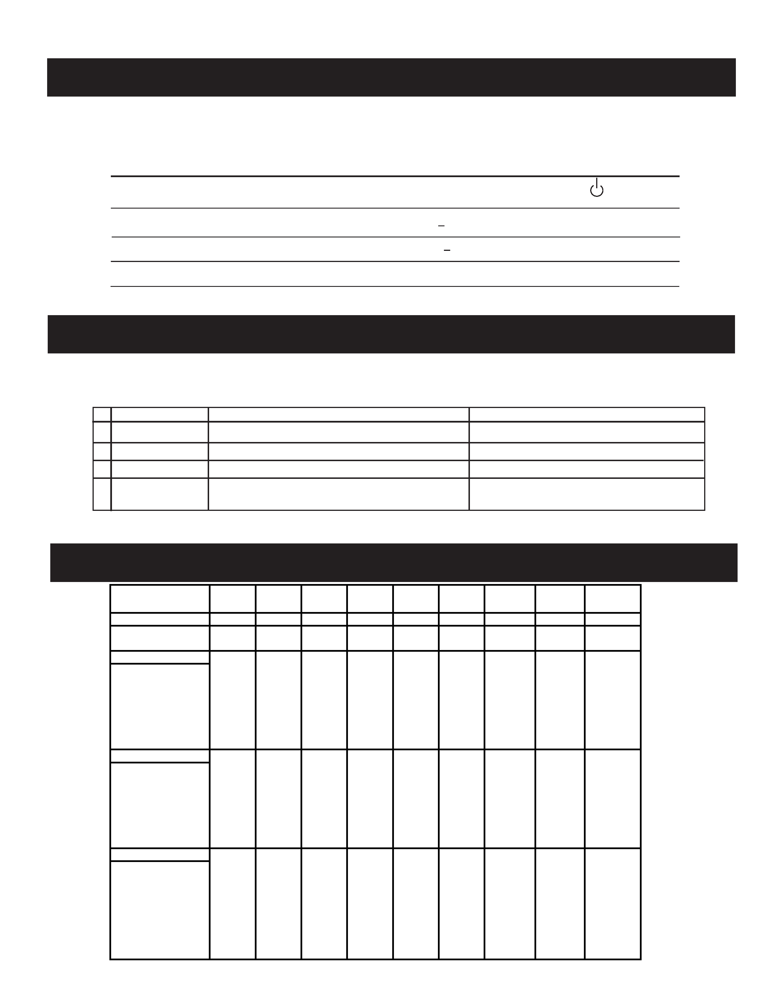
Power consumption
Screen
Horizontal
Vertical
Power
Recovery time
Indicator
mode
(video) sync signal sync signal consumption
1
Normal operation
active
yes
yes
< 100 W
--
Green
2
Active-off (3rd mode)
blank
no*
no*
< 3 W
Approx. 10 sec.
Amber
3
Power-off
--
--
--
0 W (approx)
--
Off
* In this mode, the signal will appear in one of three ways: The Horizontal Sync Signal alone off, the Vertical Sync Signal
alone off, or both signals off.
POWER MANAGEMENT
The power saving mode complies with the VESA Display Power Management Signaling standard. Each state of power management shall be activated
by the host computer terminating the appropriate sync signals. Blanking the video must precede termination of the sync signals. The elapsed time
counter shall also be controlled by the host computer. Reactivation of the monitor shall be accomplished from the host computer by re-establishing the
normal sync signal.
TIMING SPECIFICATION
SELF DIAGNOSIS FUNCTION
When a failure occurs, the STANDBY/TIMER lamp will flash a set number of times to indicate the possible cause of the problem. If there is more than
one error, the lamp will identify the first of the problem areas.
1
2
3
4
Status
Area of Failure
LED Indication
Amber (0.5 second) / Off (0.5 second)
Amber (1.5 second) / Off (0.5 second)
Amber (0.5 second) / Off (1.5 second)
Amber (0.5 second) / Off (0.5 second)/
Green (0.5 second) / Off (0.5 second)
HV or +B
H Stop, V Stop or S Correction FET Failure
ABL
Failure 1
Failure 2
Failure 3
Aging/Self Test
PRIME
MODE
MODE
1
2
3
4
5
6
7
8
9
RESOLUTION 640 X 480 640 X 480 720 X 400 800 X 600 800 X 600 832 X 624 1024 X 768 1024 X 768 1280 X 1024
CLOCK
25.175
36
28.322
49.5
56.25
57.283
78.75
94.5
108
HORIZONTAL
H. FREQ
31.469
43.269
31.469
46.875
53.674
49.725
60.023
68.677
63.981
H. TOTAL
31.778
23.111
31.777
21.333
18.631
20.111
16.660
14.561
15.630
H. BLK
6.356
5.333
6.355
5.172
4.409
5.586
3.657
3.725
3.778
H. FP
0.636
1.556
0.636
0.323
0.569
0.559
0.203
0.508
0.444
H. SYNC
3.813
1.556
3.813
1.616
1.138
1.117
1.219
1.016
1.037
H. BP
1.907
2.222
1.907
3.232
2.702
3.910
2.235
2.201
2.296
H. ACTIV
25.422
17.778
25.422
16.162
14.222
14.524
13.003
10.836
11.852
VERTICAL
V. FREQ
59.940
85.008
70.087
75.000
85.061
74.550
75.029
84.997
60.020
V. TOTAL
16.683
11.764
14.268
13.333
11.756
13.414
13.328
11.765
16.661
V. BLK
1.430
0.670
1.557
0.533
0.578
0.865
0.533
0.582
0.656
V. FP
0.318
0.023
0.381
0.021
0.019
0.020
0.017
0.015
0.016
V. SYNC
0.064
0.069
0.064
0.064
0.056
0.060
0.050
0.044
0.047
V. BP
1.049
0.578
1.112
0.448
0.503
0.784
0.466
0.524
0.594
V. ACTIV
15.253
11.093
12.711
12.800
11.179
12.549
12.795
11.183
16.005
SYNC
INT (G)
NO
NO
NO
NO
NO
NO
NO
NO
NO
EXT (H/V) / POLARITY
YES
YES
YES
YES
YES
YES
YES
YES
YES
EXT (CS) / POLARITY
NO
NO
NO
NO
NO
NO
NO
NO
NO
SERRATION
NO
NO
NO
NO
NO
NO
NO
NO
NO
SYNC LEVEL
TTL
TTL
TTL
TTL
TTL
TTL
TTL
TTL
TTL
VIDEO
VIDEO LEVEL
0.7
0.7
0.7
0.7
0.7
0.7
0.7
0.7
0.7
SET UP
0
0
0
0
0
0
0
0
0

-- 5 --
HMD-A240R
WARNINGS AND CAUTIONS
CAUTION
Short circuit the anode of the picture tube and the anode cap to the metal chassis, CRT shield, or carbon painted on the CRT, after
removing the anode.
WARNING!!
An isolation transformer should be used during any service to avoid possible shock hazard, because of live chassis. The chassis of this
receiver is directly connected to the AC power line.
! SAFETY-RELATED COMPONENT WARNING!!
Components identified by shading and ! mark on the schematic diagrams, exploded views, and in the parts list are critical for safe
operation. Replace these components with sony parts whose part numbers appear as shown in this manual or in supplements published
by sony. Circuit adjustments that are critical for safe operation are identified in this manual. Follow these procedures whenever critical
components are replaced or improper operation is suspected.
ATTENTION!!
Apres avoir deconnecte le cap de l'anode, court-circuiter l'anode du tube cathodique et celui de l'anode du cap au chassis metallique de
l'appareil, ou la couche de carbone peinte sur le tube cathodique ou au blindage du tube cathodique.
Afin d'eviter tout risque d'electrocution provenant d'un chássis sous tension, un transformateur d'isolement doit etre utilisé lors de tout
dépannage. Le chássis de ce récepteur est directement raccordé à l'alimentation du secteur.
! ATTENTION AUX COMPOSANTS RELATIFS A LA SECURITE!!
Les composants identifies par une trame et par une marque ! sur les schemas de principe, les vues explosees et les listes de pieces
sont d'une importance critique pour la securite du fonctionnement. Ne les remplacer que par des composants sony dont le numero
de piece est indique dans le present manuel ou dans des supplements publies par sony. Les reglages de circuit dont l'importance est
critique pour la securite du fonctionnement sont identifies dans le present manuel. Suivre ces procedures lors de chaque remplacement
de composants critiques, ou lorsqu'un mauvais fonctionnement suspecte.
-- 6 --
HMD-A240R
SAFETY CHECK-OUT
After correcting the original service problem, perform the following
safety checks before releasing the set to the customer:
1. Check the area of your repair for unsoldered or poorly soldered
connections. Check the entire board surface for solder splashes and
bridges.
2. Check the interboard wiring to ensure that no wires are "pinched" or
touching high-wattage resistors.
3. Check that all control knobs, shields, covers, ground straps, and
mounting hardware have been replaced. Be absolutely certain that
you have replaced all the insulators.
4. Look for unauthorized replacement parts, particularly transistors,
that were installed during a previous repair. Point them out to the
customer and recommend their replacement.
5. Look for parts which, though functioning, show obvious signs of
deterioration. Point them out to the customer and recommend their
replacement.
6. Check the line cords for cracks and abrasion. Recommend the
replacement of any such line cord to the customer.
7. Check the B+ and HV to see if they are specified values. Make sure
your instruments are accurate; be suspicious of your HV meter if
sets always have low HV.
8. Check the antenna terminals, metal trim, "metallized" knobs,
screws, and all other exposed metal parts for AC leakage. Check
leakage as described below.
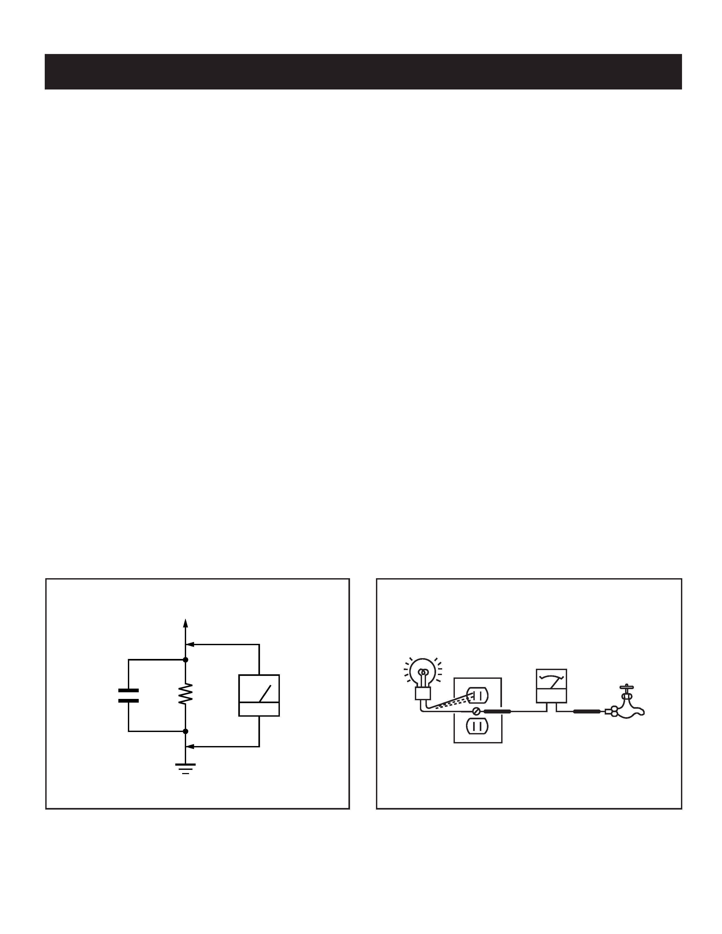
Leakage Test
The AC leakage from any exposed metal part to earth ground and from all
exposed metal parts to any exposed metal part having a return to chassis,
must not exceed 0.5 mA (500 microamperes). Leakage current can be
measured by any one of three methods.
1. A commercial leakage tester, such as the Simpson 229 or RCA
WT-540A. Follow the manufacturers' instructions to use these
instructions.
2. A battery-operated AC milliammeter. The Data Precision 245 digital
multimeter is suitable for this job.
3. Measuring the voltage drop across a resistor by means of a VOM
or battery-operated AC voltmeter. The "limit" indication is 0.75
V, so analog meters must have an accurate low voltage scale.
The Simpson's 250 and Sanwa SH-63TRD are examples of
passive VOMs that are suitable. Nearly all battery-operated digital
multimeters that have a 2 VAC range are suitable (see Figure A).
How to Find a Good Earth Ground
A cold-water pipe is a guaranteed earth ground; the cover-plate retaining
screw on most AC outlet boxes is also at earth ground. If the retaining
screw is to be used as your earth ground, verify that it is at ground
by measuring the resistance between it and a cold-water pipe with an
ohmmeter. The reading should be zero ohms.
If a cold-water pipe is not accessible, connect a 60- to 100-watt trouble-
light (not a neon lamp) between the hot side of the receptacle and the
retaining screw. Try both slots, if necessary, to locate the hot side on the
line; the lamp should light at normal brilliance if the screw is at ground
potential (see Figure B).
To Exposed Metal
Parts on Set
AC Voltmeter
(0.75 V)
Earth Ground
0.15
µF
1.5 k
Trouble Light
AC Outlet Box
Ohmmeter
Cold-water Pipe
Figure A. Using an AC voltmeter to check AC leakage.
Figure B. Checking for earth ground.